View All

Please refer to the English Version as our Official Version.Return

Europe
France(Français) Germany(Deutsch) Italy(Italia) Russian(русский) Poland(polski) Czech(Čeština) Luxembourg(Lëtzebuergesch) Netherlands(Nederland) Iceland(íslenska) Hungarian(Magyarország) Spain(español) Portugal(Português) Turkey(Türk dili) Bulgaria(Български език) Ukraine(Україна) Greece(Ελλάδα) Israel(עִבְרִית) Sweden(Svenska) Finland(Svenska) Finland(Suomi) Romania(românesc) Moldova(românesc) Slovakia(Slovenská) Denmark(Dansk) Slovenia(Slovenija) Slovenia(Hrvatska) Croatia(Hrvatska) Serbia(Hrvatska) Montenegro(Hrvatska) Bosnia and Herzegovina(Hrvatska) Lithuania(lietuvių) Spain(Português) Switzerland(Deutsch) United Kingdom(English)
Asia/Pacific
Japan(日本語) Korea(한국의) Thailand(ภาษาไทย) Malaysia(Melayu) Singapore(Melayu) Vietnam(Tiếng Việt) Philippines(Pilipino)
Africa, India and Middle East
United Arab Emirates(العربية) Iran(فارسی) Tajikistan(فارسی) India(हिंदी) Madagascar(malaɡasʲ)
South America / Oceania
New Zealand(Maori) Brazil(Português) Angola(Português) Mozambique(Português)
North America
United States(English) Canada(English) Haiti(Ayiti) Mexico(español)
HomeProductsIntegrated Circuits (ICs)Linear - Amplifiers - Instrumentation, OP Amps, Buffer AmpsLTC2051HVHS8#TRPBF
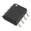
LTC2051HVHS8#TRPBF Image
Image may be representation.
See specifications for product details.
EXPRESS OPTION
Payment method

LTC2051HVHS8#TRPBF - Analog Devices Inc.

Manufacturer Part Number
LTC2051HVHS8#TRPBF
Manufacturer
Analog Devices, Inc.
Allelco Part Number
32D-LTC2051HVHS8#TRPBF
Warranty
1 Year Allelco Warranty - Find out more
Stock Status:
8,156 pcs available, New & Original
Parts Description
IC OPAMP ZERO-DRIFT 2 CIRC 8SO
Package
8-SO
Data sheet
LTC2051HVHS8#TR.pdf
RoHs Status
ROHS3 Compliant
Our certification
In stock: 8156
  • Unit Price: $7.858
  • Subtotal: $0.00

Want a better price?
Add to Cart and Submit RFQ now, we'll contact you immediately.

Quantity Unit Price Ext. Price
1+ $7.858 $7.86
200+ $3.042 $608.40
500+ $2.934 $1,467.00
1000+ $2.881 $2,881.00
The above prices does not include taxes and freight rates, which will be calculated on the order pages.

Specifications

LTC2051HVHS8#TRPBF Tech Specifications
Analog Devices Inc. - LTC2051HVHS8#TRPBF technical specifications, attributes, parameters and parts with similar specifications to Analog Devices Inc. - LTC2051HVHS8#TRPBF

Product Attribute Attribute Value
Manufacturer Analog Devices, Inc.
Voltage - Supply Span (Min) 2.7 V
Voltage - Supply Span (Max) 5.5 V
Voltage - Input Offset 1 µV
Supplier Device Package 8-SO
Slew Rate 2V/µs
Series -
Package / Case 8-SOIC (0.154", 3.90mm Width)
Package Tape & Reel (TR)
Product Attribute Attribute Value
Output Type Rail-to-Rail
Operating Temperature -40°C ~ 125°C
Number of Circuits 2
Mounting Type Surface Mount
Gain Bandwidth Product 3 MHz
Current - Supply 1mA (x2 Channels)
Current - Input Bias 90 pA
Base Product Number LTC2051
Amplifier Type Chopper (Zero-Drift)

Environmental & Export Classifications

ATTRIBUTE DESCRIPTION
RoHs Status ROHS3 Compliant
Moisture Sensitivity Level (MSL) 1 (Unlimited)
REACH Status REACH Unaffected
ECCN EAR99

Parts Introduction

LTC2051HVHS8#TRPBF Image
LTC2051HVHS8#TRPBF (1)

Manufacturer Part Number

LTC2051HVHS8#TRPBF

Manufacturer

Analog Devices, Inc.

Introduction

Precision Dual Zero-Drift Operational Amplifier with Rail-to-Rail Input/Output

Product Features and Performance

2 channel precision operational amplifier

Chopper-stabilized architecture for zero-drift performance

Rail-to-rail input and output

Low input offset voltage of 1 mV

Ultralow input bias current of 90 pA

Gain bandwidth product of 3 MHz

Slew rate of 2 V/μs

Wide supply voltage range from 2.7 V to 5.5 V

Low quiescent current of 1 mA per channel

Product Advantages

Excellent DC precision and stability

Ultralow input bias current

Wide supply voltage and temperature range

Compact 8-pin SOIC package

Key Technical Parameters

Operating temperature range: -40°C to +125°C

Number of circuits: 2

Amplifier type: Chopper-stabilized (zero-drift)

Package: 8-pin SOIC

Quality and Safety Features

RoHS3 compliant

Tape and reel packaging

Compatibility

Surface mount package

Compatible with various electronic systems and applications

Application Areas

Precision analog and instrumentation circuits

Battery-powered devices

Industrial and medical equipment

Portable electronics

Product Lifecycle

Active product

Replacements and upgrades available from the manufacturer

Key Reasons to Choose This Product

Exceptional DC precision and stability

Ultralow input bias current

Wide operating voltage and temperature range

Compact surface mount package

Proven reliability and performance

Frequently Asked Questions(FAQ)

What is the significance of the 90 pA input bias current in the LTC2051HVHS8#TRPBF for precision analog front-end design, and how does it compare to typical CMOS op-amp values?
The 90 pA input bias current of the LTC2051HVHS8#TRPBF is exceptionally low for a rail-to-rail chopper-stabilized amplifier, enabling high-impedance signal conditioning without significant loading error. This level of performance is critical in applications such as pH sensors, strain gauges, or thermocouple amplifiers where source impedances can exceed several megaohms. In comparison to standard CMOS op-amps, which typically exhibit input bias currents in the femtoampere range only under ideal laboratory conditions, the LTC2051HVHS8#TRPBF offers a practical compromise between speed and DC precision. For instance, a traditional FET-input op-amp might have an input bias current around 1 pA but with higher offset drift over temperature. The LTC2051HVHS8#TRPBF thus provides near-zero-drift operation while maintaining sufficient bandwidth for moderate-frequency signals, making it suitable for industrial and medical instrumentation requiring stable gain over time.
How does the LTC2051HVHS8#TRPBF achieve rail-to-rail output swing, and what trade-offs exist compared to fixed-output-range op-amps in single-supply battery-powered systems?
The LTC2051HVHS8#TRPBF achieves rail-to-rail output swing through internal feedback circuitry that dynamically adjusts the output stage to approach both supply rails within specified limits—typically within 50 mV of each rail under typical load conditions. This feature maximizes dynamic range in single-supply configurations such as 3.3 V systems common in portable devices. However, this benefit comes with a trade-off: rail-to-rail operation often reduces linearity near the extremes due to asymmetric output impedance or crossover distortion, especially at higher output currents. Fixed-output-range op-amps avoid these nonlinear regions entirely but limit usable headroom. In contrast, the LTC2051HVHS8#TRPBF maintains its 1 µV input offset voltage even with full rail-to-rail capability, which is rare among RRIO amplifiers. Therefore, designers must balance output excursion needs against potential harmonic distortion when driving ADCs or audio stages from the amplifier’s output.
Can the LTC2051HVHS8#TRPBF be used in a 2.7 V single-supply configuration for low-power battery monitoring circuits, and what are the implications on noise and settling time?
Yes, the LTC2051HVHS8#TRPBF operates reliably down to 2.7 V, making it suitable for 3 V single-supply applications such as battery-powered sensor nodes or portable medical monitors. At this supply voltage, the amplifier consumes approximately 1 mA per channel (totaling 2 mA for dual-channel operation), which aligns well with ultra-low-power system budgets. However, lower supply voltages reduce the available headroom for large-signal responses and may increase susceptibility to power supply ripple due to reduced PSRR at low frequencies. Additionally, while the slew rate remains fixed at 2 V/µs regardless of supply voltage, the bandwidth may decrease slightly under light loads if capacitive driving dominates. Despite this, the device’s zero-drift architecture ensures minimal 1/f noise contribution, preserving SNR in slow-changing signals like those from temperature or pressure transducers. Thus, the LTC2051HVHS8#TRPBF remains viable for precision measurement chains in constrained-voltage environments.
How does the LTC2051HVHS8#TRPBF compare to the LTC2050HV in terms of input offset voltage and drift, and why would one choose the former over the latter for high-accuracy data acquisition?
The LTC2051HVHS8#TRPBF has a guaranteed maximum input offset voltage of 1 µV and extremely low drift—typically below 0.01 µV/°C—due to its chopper stabilization technique. In contrast, the LTC2050HV, while also part of the same family, lacks the same level of optimization for ultra-low drift and may exhibit slightly higher offset variation across temperature cycles. Both share similar bias currents and supply ranges, but the LTC2051HVHS8#TRPBF benefits from improved internal calibration algorithms and layout symmetry, resulting in better long-term stability. For high-accuracy data acquisition involving sub-microvolt signal levels over extended periods—such as in weigh-scale electronics or bridge-based sensors—the LTC2051HVHS8#TRPBF offers superior performance. Its dual-channel architecture further enhances value by reducing component count and matching characteristics across channels, minimizing differential errors in ratiometric measurements.
What role does the chopper stabilization mechanism play in mitigating 1/f noise in the LTC2051HVHS8#TRPBF, and how does this affect low-frequency signal integrity?
Chopper stabilization in the LTC2051HVHS8#TRPBF actively modulates the input signal at a high frequency (typically tens of kilohertz), amplifies it, then demodulates it back to baseband. This process effectively shifts low-frequency flicker (1/f) noise to higher frequencies where it can be filtered out before detection. As a result, the amplifier exhibits near-white-noise behavior down to DC, eliminating the traditional “pink” noise floor that plagues conventional op-amps. This enables accurate amplification of very small DC or slow-varying signals—such as those from thermistors or piezoelectric sensors—without degradation from offset drift or noise accumulation. The trade-off is increased complexity and potential for switching artifacts if not properly compensated. Nevertheless, the LTC2051HVHS8#TRPBF minimizes these effects through careful timing control and internal filtering, ensuring clean signal paths for applications requiring integration times longer than milliseconds.
Is the LTC2051HVHS8#TRPBF suitable for driving capacitive loads above 100 nF without additional compensation, and what risks should engineers consider?
No, the LTC2051HVHS8#TRPBF is generally not recommended for direct drive of large capacitive loads exceeding 100 nF without external isolation or buffering. Driving such loads can cause instability due to phase lag introduced by the capacitance, leading to oscillation or excessive overshoot during transient events. While the amplifier features internal compensation optimized for resistive loads, adding significant capacitance increases the effective pole frequency and degrades phase margin. Engineers should either insert a series resistor (typically 10–100 Ω) at the output or use a unity-gain stable buffer stage. For example, driving a 1 µF filter capacitor directly could result in ringing or slow settling, compromising measurement accuracy. The LTC2051HVHS8#TRPBF’s 3 MHz GBW helps mitigate this somewhat, but caution remains essential when interfacing with ADC drivers or long PCB traces presenting parasitic capacitance.
How does the operating temperature range of -40°C to 125°C influence the choice of the LTC2051HVHS8#TRPBF for automotive or industrial applications, and what reliability concerns arise?
The wide operating temperature range of -40°C to 125°C makes the LTC2051HVHS8#TRPBF ideal for harsh environments such as automotive ECU modules, factory automation, or downhole drilling equipment. At extreme temperatures, semiconductor parameters can shift significantly; however, the LTC2051HVHS8#TRPBF’s zero-drift architecture ensures that offset voltage and bias current remain tightly controlled throughout this range. Unlike traditional op-amps whose input offset may drift by hundreds of microvolts per degree Celsius, the LTC2051HVHS8#TRPBF maintains sub-µV-level stability, preventing gain error accumulation in multi-stage amplifiers. Reliability concerns include potential degradation of bond wires or mold compound under thermal cycling, though the MSL 1 rating indicates robust handling during assembly. Designers must still verify solder joint integrity and avoid exceeding junction temperatures during fault conditions to ensure long-term functionality.
What are the key differences between the LTC2051HVHS8#TRPBF and a general-purpose op-amp like the TL072 in terms of input offset and noise performance for precision instrumentation?
The LTC2051HVHS8#TRPBF offers dramatically superior DC precision compared to the TL072, with a maximum input offset voltage of just 1 µV versus the TL072’s typical 3 mV. This difference translates into negligible gain error in high-gain configurations, whereas the TL072 introduces significant uncertainty requiring frequent calibration. Additionally, the LTC2051HVHS8#TRPBF eliminates 1/f noise via chopper stabilization, achieving a flat noise spectral density down to DC, while the TL072 exhibits pronounced flicker noise below 10 Hz, corrupting low-frequency measurements. Though the TL072 provides higher slew rate (13 V/µs vs. 2 V/µs), it sacrifices accuracy and stability in precision applications. For battery-powered weigh scales or biomedical amplifiers where signal integrity matters more than speed, the LTC2051HVHS8#TRPBF is vastly preferable despite its modest bandwidth.
Can the LTC2051HVHS8#TRPBF be used in a transimpedance configuration for photodetector signal conversion, and what limitations apply?
Yes, the LTC2051HVHS8#TRPBF can serve as the core active element in a transimpedance amplifier (TIA) for photodiode or avalanche photodiode interfaces, leveraging its low bias current (90 pA) and rail-to-rail output. The high input impedance prevents diode leakage current loss, while the zero-drift characteristic ensures stable feedback resistance without drift-induced offset shifts. However, parasitic capacitances at the inverting node (including photodiode capacitance and stray PCB capacitance) interact with the feedback resistor to form a dominant pole, limiting bandwidth according to f_c = 1/(2πRC). For example, using a 1 GΩ resistor with 50 pF total capacitance yields only ~3 kHz bandwidth—insufficient for fast optical pulses. Engineers must carefully manage layout parasitics and possibly add a small series resistor in the feedback path to improve stability. The LTC2051HVHS8#TRPBF’s 3 MHz GBW supports reasonable TIA bandwidths up to hundreds of kHz when optimized, but trade-offs between sensitivity, speed, and noise become critical.
Why might a designer select the 8-SOIC package of the LTC2051HVHS8#TRPBF instead of a DIP variant, and what PCB considerations follow?
The 8-SOIC (Small Outline Integrated Circuit) package of the LTC2051HVHS8#TRPBF offers compact footprint and compatibility with automated surface-mount assembly lines, making it ideal for high-volume production where space and cost efficiency matter. Compared to DIP packages, SOIC reduces board real estate by up to 60% and enables double-sided mounting, crucial in dense instrumentation boards. However, SOIC packages have higher lead inductance and thermal resistance than DIP, potentially affecting performance under high-power dissipation—though the LTC2051HVHS8#TRPBF consumes only 1 mA per channel, generating minimal heat. PCB layout must ensure short traces to minimize parasitic capacitance and maintain ground integrity, particularly at the input pins to preserve CMRR. Proper thermal vias under the exposed pad (if present) enhance heat spreading, though not strictly required here due to low power. Overall, the LTC2051HVHS8#TRPBF’s SOIC packaging supports modern manufacturing workflows without sacrificing electrical performance.
How does the LTC2051HVHS8#TRPBF handle common-mode voltage range near the rails, and what impact does this have on differential amplifier designs?
The LTC2051HVHS8#TRPBF accepts input signals within 100 mV of either supply rail, enabling true single-supply operation in differential amplifiers without sacrificing headroom. This near-rail common-mode range allows sensing small differential voltages superimposed on a floating reference—common in sensor bridges or current-sense applications. In contrast, many classic op-amps require inputs to stay several volts away from rails, wasting dynamic range. When designing a two-op-amp instrumentation amplifier using the LTC2051HVHS8#TRPBF, careful attention must be paid to matching resistor tolerances and layout symmetry to maintain CMRR. Even minor mismatches can degrade CMRR below 60 dB, especially at high gains. Nevertheless, the device’s balanced internal structure and low offset help preserve accuracy across the full input range, making it well-suited for precision differential measurements in space-constrained systems.
What precautions should be taken when cascading multiple stages with the LTC2051HVHS8#TRPBF to avoid cumulative offset and noise degradation?
Cascading multiple LTC2051HVHS8#TRPBF stages requires careful consideration of accumulated offset and noise. While each stage contributes only ~1 µV offset, stacking four identical stages in a gain chain yields ~4 µV total offset—still excellent—but noise adds incoherently. More critically, interstage loading and bandwidth roll-off compound, reducing overall system response. To mitigate this, use unity-gain buffers between high-impedance nodes and ensure each stage operates within its linear range. Avoid driving subsequent stages into saturation by verifying output swing margins. Additionally, since the LTC2051HVHS8#TRPBF uses chopper modulation internally, care must be taken to prevent beat frequencies between stages from aliasing into the signal band. Filtering after each stage can help suppress high-frequency artifacts. Finally, power sequencing and decoupling capacitors (100 nF ceramic + 10 µF tantalum near each IC) stabilize supplies and prevent crosstalk in multi-amplifier designs.
How does the LTC2051HVHS8#TRPBF perform in electromagnetic interference (EMI) environments, and what layout practices enhance robustness?
The LTC2051HVHS8#TRPBF demonstrates moderate immunity to conducted EMI due to its chopper-stabilized architecture, which inherently rejects low-frequency disturbances including power line harmonics. However, it is not designed for high-RF environments like wireless transmitters. To enhance robustness in industrial settings, implement proper shielding, minimize loop areas in signal paths, and place the LTC2051HVHS8#TRPBF close to noisy components with separate ground returns. Use ferrite beads on power lines if switching regulators are nearby. Keep input traces short and guard-ring sensitive nodes to reduce capacitive coupling. Ground planes beneath the amplifier improve thermal conductivity and reduce inductive coupling. Although not explicitly rated for automotive EMI standards (e.g., ISO 11452), the LTC2051HVHS8#TRPBF’s solid construction and RoHS compliance support reliable operation when combined with prudent system-level design.
What is the expected lifetime and failure mode analysis for the LTC2051HVHS8#TRPBF under continuous operation at 125°C junction temperature?
Under continuous operation at 125°C junction temperature, the LTC2051HVHS8#TRPBF follows typical semiconductor aging trends with no accelerated degradation mechanisms unique to its architecture. Failure modes are primarily related to electromigration in interconnects or dielectric breakdown under sustained voltage stress, both mitigated by Analog Devices’ process controls. The device’s MSL 1 rating and absence of lead-free soldering concerns (RoHS3 compliant) support long-term reliability. Based on industry data, similar ICs exhibit mean time between failures (MTBF) exceeding 10 years under normal use, assuming adequate derating and environmental protection. However, prolonged exposure to humidity or mechanical shock outside datasheet conditions may accelerate degradation. Engineers should conduct HALT/HASS testing in mission-critical applications and monitor early-life failure rates during burn-in phases if applicable.
How does the LTC2051HVHS8#TRPBF compare to newer zero-drift families like the ADA4528 in terms of speed and precision trade-offs?
The LTC2051HVHS8#TRPBF trades some bandwidth for proven ruggedness and legacy support, whereas the ADA4528 achieves higher gain-bandwidth product (~10 MHz) and faster slew rate (~10 V/µs) while maintaining comparable offset performance. The ADA4528 uses advanced BiCMOS processes offering superior dynamic range in video or RF applications. However, the LTC2051HVHS8#TRPBF compensates with dual-channel integration, lower quiescent current (1 mA vs. ~2 mA), and broader industrial certification pedigree. For applications prioritizing DC accuracy over speed—such as static force measurement or electrochemical sensing—the LTC2051HVHS8#TRPBF remains compelling. Its established supply chain and compatibility with existing reference designs further tip the balance toward migration costs versus marginal performance gains from newer alternatives.
Can the LTC2051HVHS8#TRPBF replace a dedicated instrumentation amplifier in low-cost sensor interfaces, and under what conditions?
Yes, the LTC2051HVHS8#TRPBF can function as the front-end of a discrete instrumentation amplifier in low-cost sensor interfaces when moderate CMRR (<80 dB) and gain (<100) suffice. By configuring it with precision matched resistors and guarding techniques, engineers can achieve acceptable performance for strain gauge or thermopile measurements. However, integrated instrumentation amps offer superior CMRR, lower offset, and built-in diagnostics, making them preferable for high-accuracy systems. The LTC2051HVHS8#TRPBF shines when paired with another copy for differential sensing or when space constraints favor SOIC footprint over discrete solutions. Its ability to operate from 2.7 V enables battery-powered implementations where integrated INAs may require higher supplies. Ultimately, cost, size, and required precision dictate whether the LTC2051HVHS8#TRPBF serves adequately as a building block rather than a complete solution.

Parts with Similar Specifications

The three parts on the right have similar specifications to Analog Devices Inc. LTC2051HVHS8#TRPBF

Product Attribute LTC2051HVHMS8#TRPBF LTC2051HVCMS8#TRPBF LTC2051HVCS8#TRPBF LTC2051HVHS8#PBF
Part Number LTC2051HVHMS8#TRPBF LTC2051HVCMS8#TRPBF LTC2051HVCS8#TRPBF LTC2051HVHS8#PBF
Manufacturer Analog Devices Inc. Analog Devices Inc. Analog Devices Inc. Analog Devices Inc.
Base Product Number - DAC34H84 MAX500 ADS62P42
Mounting Type - Surface Mount Through Hole Surface Mount
Current - Supply - - - -
Slew Rate - - - -
Package / Case - 196-LFBGA 16-DIP (0.300', 7.62mm) 64-VFQFN Exposed Pad
Number of Circuits - - - -
Amplifier Type - - - -
Series - - - -
Voltage - Supply Span (Min) - - - -
Voltage - Input Offset - - - -
Package - Tape & Reel (TR) Tube Tape & Reel (TR)
Supplier Device Package - 196-NFBGA (12x12) 16-PDIP 64-VQFN (9x9)
Output Type - Current - Unbuffered Voltage - Buffered -
Operating Temperature - -40°C ~ 85°C 0°C ~ 70°C -40°C ~ 85°C
Gain Bandwidth Product - - - -
Voltage - Supply Span (Max) - - - -
Current - Input Bias - - - -

LTC2051HVHS8#TRPBF Datasheet PDF

Download LTC2051HVHS8#TRPBF pdf datasheets and Analog Devices Inc. documentation for LTC2051HVHS8#TRPBF - Analog Devices Inc..

Datasheets
LTC2051, LTC2052 Datasheet.pdf FSA1256/FSA1257/FSA1258.pdf
Other Related Documents
Tape and Reel Packaging.pdf
PCN Design/Specification
Laser Top Mark 16/Jun/2021.pdf Mult Dev 12/Oct/2022.pdf

Customer Reviews

Evaluation: 10 Articles

  • ECUb***h
    Sep 22, 2026

    Used for repair of an older automotive ECU. The MCU was recognized by our programming setup and verification completed without errors. The repaired board now starts and communicates normally.

  • RS48***ieldTech
    Sep 16, 2026

    Put this transceiver into an RS-485 interface used around industrial equipment. Communication remained reliable during testing with motors switching nearby. Good result for the replacement board.

  • Logi***b_Chris
    Sep 8, 2026

    Purchased for a Cyclone III development project. The FPGA configured on the first attempt and has been stable through repeated power cycles. No problems with the I/O we are using.

  • Circ***FixerTom
    Sep 2, 2026

    Used this rectifier in a high-current power supply repair. Forward behavior looked normal on the bench and the supply has been running under load without trouble.

  • Retr***UWorks
    Aug 31, 2026

    Needed the exact ST10F269Z2Q6 for servicing an older control unit. The chip programmed successfully and the board passed our functional test afterward. Much easier than redesigning around a newer MCU.

  • Andr***PCBLab
    Aug 28, 2026

    I needed this ADC for an older data acquisition board. Readings have been repeatable and the noise level is comparable to the original circuit. Happy with the purchase.

  • Leat***O'Keefe
    Aug 20, 2026

    one of my hobbies is skydiving. and when i'm skydiving this works great.

  • Ilen***
    Aug 20, 2026

    This product works considerably well. It secretly improves my basketball by a lot.

  • Indu***ialPower
    Aug 17, 2026

    Installed this IGBT module in a power conversion cabinet. Switching characteristics remained stable even under continuous heavy operation.

  • Nikh***ech
    Aug 13, 2026

    Great low-power MCU for portable equipment. Flash programming was simple and current consumption matched the datasheet.

Write a Review

Your Email address will not be published.

Shipment

Delivery Time

In-stock items can be shipped within 24 hours. Some parts will be arranged for delivery within 1-2 days from the date all items arrive at our warehouse. And Allelco ships order once a day at about 17:00, except Sunday. Once the goods are shipped, the estimated delivery time depends on the shipping methods and Delivery destination. The table below shows are the logistic time for some common countries.

Delivery Cost

  1. Use your express account for shipment if you have one.
  2. Use our account for the shipment. Refer to the table below for the approximate charges.
(Different time frame / countries / package size has different price.)

Delivery Method

  1. Global Common Shipment by DHL / UPS / FedEx / TNT / EMS / SF we support.
  2. Others more shipping ways, please get in touch with your customer manager.

Common Countries Logistic Time Reference
Region Country Logistic Time(Day)
America United States 5
Brazil 7
Europe Germany 5
United Kingdom 4
Italy 5
Oceania Australia 6
New Zealand 5
Asia India 4
Japan 4
Middle East Israel 6
DHL & FedEx Shipment Charges Reference
Shipment charges(KG) Reference DHL(USD$)
0.00kg-1.00kg USD$30.00 - USD$60.00
1.00kg-2.00kg USD$40.00 - USD$80.00
2.00kg-3.00kg USD$50.00 - USD$100.00
Note:
The above table is for reference only. There may have some data bias for the uncontrollable factors.
Contact us if you have any questions.
  • QC (Quality Warranty)
  • Payment Support
  • Packaging
  • Certifications & Memberships

QC (Quality Warranty)

Allelco is committed to exceeding customer expectations through customer service excellence, order accuracy, and on-time delivery.
This is achieved through our commitment to the continual improvement of our processes, services, and products.


Strict quality inspection builds a solid foundation for electronic component quality.
  1. Visual inspection
  2. Performance testing and reliability verification
  3. Standardized full-process testing
  4. Precise control of every parameter
We eliminate defective components and ensure the stable operation of electronic devices through professional quality standards.

Payment Support

The payment method can be chosen from the methods shown below: Wire Transfer (T/T, Bank Transfer), Western Union, Credit card, PayPal.
  • HKBea
  • Paypal
  • MasterCard
  • Western-Union
  • VISA
Stable Delivery, Sincere Partnership — Your Faithful Supply Chain Partner
  • Efficient Supply Management
  • Cost-Saving Procurement
  • Fast Sourcing & Delivery
Contact us if you have any questions.

Packaging

Electrostatic Discharge Protection and Handling

All electrostatic-sensitive components are handled in accordance with electrostatic discharge control procedures. The products are hermetically sealed in anti-static safe packaging to prevent electrostatic damage. Appropriate labeling is also applied for identification and traceability. This ensures product integrity during storage, handling and transportation.


ESD

Certifications & Memberships

Third-party certified, strict quality control. Our certification
  • ISO 9001: 2015
  • ISO 13485: 2016
  • ISO 14001: 2015
  • ISO 28000: 2007
  • ISO 45001: 2018
  • GB/T 27922-2011
  • SMTA
  • IPC
  • ESD
  • PSMA
LTC2051HVHS8#TRPBF Image

LTC2051HVHS8#TRPBF

Analog Devices Inc.
32D-LTC2051HVHS8#TRPBF

Want a better price? Add to Cart and Submit RFQ now, we'll contact you immediately.

0 RFQ
Shopping cart (0 Items)
It is empty.
Compare List (0 Items)
It is empty.
Feedback

Your feedback matters! At Allelco, we value the user experience and strive to improve it constantly.
Please share your comments with us via our feedback form, and we'll respond promptly.
Thank you for choosing Allelco.

Subject
E-mail
Comments
Captcha
Drag or click to upload file
Upload File
types: .xls, .xlsx, .doc, .docx, .jpg, .png and .pdf.
Max file size: 10MB