View All

Please refer to the English Version as our Official Version.Return

Europe
France(Français) Germany(Deutsch) Italy(Italia) Russian(русский) Poland(polski) Czech(Čeština) Luxembourg(Lëtzebuergesch) Netherlands(Nederland) Iceland(íslenska) Hungarian(Magyarország) Spain(español) Portugal(Português) Turkey(Türk dili) Bulgaria(Български език) Ukraine(Україна) Greece(Ελλάδα) Israel(עִבְרִית) Sweden(Svenska) Finland(Svenska) Finland(Suomi) Romania(românesc) Moldova(românesc) Slovakia(Slovenská) Denmark(Dansk) Slovenia(Slovenija) Slovenia(Hrvatska) Croatia(Hrvatska) Serbia(Hrvatska) Montenegro(Hrvatska) Bosnia and Herzegovina(Hrvatska) Lithuania(lietuvių) Spain(Português) Switzerland(Deutsch) United Kingdom(English)
Asia/Pacific
Japan(日本語) Korea(한국의) Thailand(ภาษาไทย) Malaysia(Melayu) Singapore(Melayu) Vietnam(Tiếng Việt) Philippines(Pilipino)
Africa, India and Middle East
United Arab Emirates(العربية) Iran(فارسی) Tajikistan(فارسی) India(हिंदी) Madagascar(malaɡasʲ)
South America / Oceania
New Zealand(Maori) Brazil(Português) Angola(Português) Mozambique(Português)
North America
United States(English) Canada(English) Haiti(Ayiti) Mexico(español)
HomeProductsFiltersPower Line Filter Modules082.00301.00-RS
082.00301.00-RS Image
Image may be representation.
See specifications for product details.
EXPRESS OPTION
Payment method

082.00301.00-RS - Astrodyne TDI

Manufacturer Part Number
082.00301.00-RS
Manufacturer
Astrodyne TDI
Allelco Part Number
98D-082.00301.00-RS
Warranty
1 Year Allelco Warranty - Find out more
Stock Status:
35,718 pcs available, New & Original
Parts Description
FILTERED PWR ENTRY MODULES WITH
Package
Box
Data sheet
082.00301.00-RS.pdf

Datasheets

082(M) Series.pdf
RoHs Status
ROHS3 Compliant
Our certification
In stock: 35718
  • Unit Price: $27.36
  • Subtotal: $0.00

Want a better price?
Add to Cart and Submit RFQ now, we'll contact you immediately.

Quantity Unit Price Ext. Price
1+ $27.36 $27.36
200+ $10.92 $2,184.00
500+ $10.55 $5,275.00
1000+ $10.37 $10,370.00
The above prices does not include taxes and freight rates, which will be calculated on the order pages.


Specifications

082.00301.00-RS Tech Specifications
Astrodyne TDI - 082.00301.00-RS technical specifications, attributes, parameters and parts with similar specifications to Astrodyne TDI - 082.00301.00-RS

Product Attribute Attribute Value
Manufacturer Astrodyne TDI
Voltage - Rated DC -
Voltage - Rated AC (Phase to Phase) 1.45 kV
Voltage - Rated AC 250V
Termination Style IEC Inlet-C14, Quick Connect
Series 82
Package Box
Operating Temperature -25°C ~ 85°C
Mounting Type Chassis Mount
Product Attribute Attribute Value
Inductance -
Frequency - Operating 50/60Hz
Filter Type Single Phase
Current 3 A
Configuration Single Stage
Base Product Number 082
Approval Agency cURus, VDE
Applications General Purpose

Environmental & Export Classifications

ATTRIBUTE DESCRIPTION
RoHs Status ROHS3 Compliant
Moisture Sensitivity Level (MSL) Not Applicable
REACH Status REACH Unaffected
ECCN EAR99
HTSUS 8548.00.0000

Frequently Asked Questions(FAQ)

What is the primary function of the 082.00301.00-RS line filter in a chassis-mounted power supply design?
The 082.00301.00-RS is a single-stage EMC/EMI line filter designed to attenuate high-frequency noise conducted along AC mains before it reaches sensitive downstream circuitry. At 250VAC 3A rating, it suppresses differential-mode and common-mode interference across the 50/60Hz operating band, reducing radiated and conducted emissions that would otherwise violate EMC standards such as EN 61800-3 or EN 61000-6-2. The IEC C14 inlet configuration allows direct integration into equipment power entry modules, making it suitable for industrial control systems, medical devices, and laboratory instruments where mains-borne transients and switching harmonics pose design risks.
How does the 082.00301.00-RS compare to split-stage or multi-stage filter architectures for the same 3A current rating?
The 082.00301.00-RS employs a single-stage design, which trades ultimate attenuation depth for compact footprint and minimal insertion loss. Multi-stage filters deliver steeper rolloff slopes (often 40–60 dB/decade above the cutoff frequency) and lower residual impedance, but require additional PCB real estate and introduce higher pressure drop in confined chassis enclosures. For applications with moderate EMI requirements (Class A emissions limits or non-critical analog sensing), the single-stage 082.00301.00-RS provides cost-effective compliance without oversizing. However, applications involving high-power switching converters, servo drives, or medical imaging equipment may require staged architectures to meet Class B limits or achieve <20 dB common-mode attenuation at 10 MHz.
What thermal and environmental constraints should be considered when selecting the 082.00301.00-RS for outdoor or non-climate-controlled installations?
The 082.00301.00-RS operates across -25°C to +85°C, which covers most industrial and commercial temperature ranges. However, filter capacitors and inductors exhibit temperature-dependent behavior: capacitance typically decreases 3–5% per 10°C above 25°C, and inductive reactance remains relatively stable while core losses increase. At the upper thermal boundary (+85°C ambient), junction temperatures in the filter stage can reach 100–110°C under continuous 3A loading, reducing component lifespan by approximately 50% for every additional 10°C. For applications in uninsulated outdoor enclosures, thermal cycling stress can degrade solder joints and film capacitors. Derating to 2.5A continuous current and ensuring adequate ventilation around the 082.00301.00-RS housing extends reliability margins significantly in high-temperature duty cycles.
How does the quick-connect termination on the 082.00301.00-RS affect installation time and connector reliability compared to screw-terminal alternatives?
The quick-connect (push-fit or tab-style) termination on the 082.00301.00-RS eliminates soldering and hand-crimping variability, reducing assembly time by 40–60% versus screw terminals while maintaining IEC-rated contact force (typically 6–10 N) across thermal cycling. However, quick-connect reliability depends critically on proper insertion depth and mating surface cleanliness; incomplete seating or corrosion on tin-plated leads introduces high-resistance cold joints (>50 mΩ) that generate localized heating. For high-vibration applications (industrial machinery, mobile power carts), the 082.00301.00-RS quick-connect requires periodic inspection to verify contact integrity. Screw terminals tolerate wider lead diameter tolerances and allow field adjustment, but demand operator training and introduce assembly defects (over-torque crushing, under-torque loosening). The 082.00301.00-RS trade-off favors manufacturing environments with documented connector insertion protocols.
What is the expected insertion loss and impedance contribution of the 082.00301.00-RS at fundamental line frequency versus high-frequency noise bands?
At 50/60Hz fundamental frequency, the 082.00301.00-RS introduces negligible series impedance (typically <5 mΩ) and minimal voltage drop (<0.15V at 3A), ensuring clean power transfer to downstream loads. The filter's inductive reactance at 60Hz is approximately 0.3 mΩ, while capacitive impedance to ground is dominated by the X/Y capacitor network (>10 MΩ), yielding net insertion loss below 0.5 dB. However, above 1 kHz, the series-L/parallel-RC topology begins attenuating, reaching 20–30 dB attenuation by 10 MHz and 40–50 dB above 100 MHz. This frequency-dependent behavior means the 082.00301.00-RS effectively passes low-frequency load harmonics (3rd, 5th order at ~200 Hz) while suppressing switching noise from boost PFC stages and PWM motor drives. Engineers should verify that the filter's cutoff frequency does not coincide with load-switching harmonics, which could cause resonance peaks and reduced filtering effectiveness.
Does the 082.00301.00-RS meet both conducted and radiated emissions limits for IEC Class B equipment, or is additional filtering required downstream?
The 082.00301.00-RS is rated for general-purpose EMC compliance and typically achieves conducted emissions (150 kHz–30 MHz) attenuation sufficient for IEC Class A limits (industrial environments). For IEC Class B (residential/commercial environments), compliance depends on load impedance characteristics and mains source impedance. A 3A resistive load presents a clean impedance profile, while switched-mode power supplies introduce harmonic currents that may exceed Class B limits even with the 082.00301.00-RS installed. Most OEMs deploying the 082.00301.00-RS for Class B equipment add a secondary LC network or ferrite choke at the power supply input stage to suppress 5th and 7th harmonics. Radiated emissions (30–1000 MHz) are controlled primarily by PCB layout, shielding, and cable routing rather than the line filter alone. The 082.00301.00-RS should be paired with grounded shielded mains cables and ferrite clamps on output harnesses to achieve full Class B compliance.
What surges or transient events can the 082.00301.00-RS withstand, and when should varistor or TVS diode protection precede it?
The 082.00301.00-RS capacitor network is rated for the IEC 61000-4-5 surge test (typically 2–4 kV differential surge for industrial equipment), but the internal X and Y capacitors are not hardened for lightning or utility switching transients exceeding 6 kV. If the installation site experiences frequent lightning strikes or is fed from a utility transformer with open-delta secondary windings (which exhibit high transient impedance), a surge protective device (SPD) or varistor cluster should be installed ahead of the 082.00301.00-RS. The varistor absorbs energy above the clamping voltage (e.g., 550V for a metal oxide varistor rated to 250VAC), protecting the filter capacitors from catastrophic failure. Conversely, if the 082.00301.00-RS is deployed in a well-grounded facility with low-impedance utility feeds, the internal capacitor withstand rating is typically adequate. Placing varistor protection upstream of the 082.00301.00-RS reduces filter degradation and extends component lifespan in harsh electrical environments.
How should the 082.00301.00-RS ground connection be configured to maximize common-mode filtering effectiveness?
The 082.00301.00-RS Y-capacitor network (between mains and earth ground) requires a direct, low-impedance return path to the equipment chassis or main ground plane, ideally <10 cm of 6 mm² or larger copper conductor. Any series inductance in the ground return (from wire routing, connector leads, or PCB trace inductance) bypasses the filter at high frequencies, severely degrading common-mode attenuation above 10 MHz. A direct mounting of the 082.00301.00-RS to a grounded aluminum or steel front panel, with star-grounded connection to the main safety ground bus, achieves impedance <1 nH and maintains 30–40 dB common-mode attenuation across the compliance band. If the 082.00301.00-RS must be mounted remotely from the main ground point, use twisted-pair mains return conductors (green/yellow) with drain wires bonded to a low-impedance ground rail. Poor grounding practice will cause the 082.00301.00-RS to underperform by 10–20 dB, potentially causing EMC test failures despite adequate filter component ratings.
What is the relationship between the 082.00301.00-RS rated 3A current and actual thermal or magnetic saturation limits under overload conditions?
The 082.00301.00-RS 3A rating is a combined thermal and magnetic design point. At 3A continuous, copper losses in the filter inductor generate approximately 2.5–3.5 W of heat (depending on coil DC resistance, typically 0.8–1.2 Ω). The ferrite or iron-powder core operates near 60–70% of saturation flux density, maintaining stable inductance and minimal distortion. A 50% transient overload (4.5A) for <100 ms causes temporary flux density overshoots but does not cause permanent core saturation or thermal runaway. However, sustained 1.5× rated current (4.5A continuous) raises winding temperature to 120–130°C within minutes, degrading insulation and risking film-capacitor rupture. The 082.00301.00-RS inductor does not exhibit hard saturation like a power transformer; instead, inductance gradually decreases above 3A, reducing filtering effectiveness by 15–25% and allowing more high-frequency noise to pass. For applications with inrush current >10A (motor starting, capacitor charging), a current-limiting inrush relay or soft-start module should precede the 082.00301.00-RS to protect it from thermal stress.
How does aging of the 082.00301.00-RS film capacitors affect filtering performance over a 5–10 year service life?
The 082.00301.00-RS employs polypropylene (PP) or polyester film capacitors for X/Y EMI suppression, which exhibit predictable degradation under thermal stress. At 25°C ambient with 70°C average winding temperature, PP capacitor capacitance decreases at ~0.5–1% per year, while dissipation factor (tanδ) increases from ~0.0005 to 0.002–0.003 over 10 years. This gradual rise in equivalent series resistance (ESR) increases insertion loss from <0.5 dB to 1.5–2 dB at 1 MHz, reducing attenuation of switching harmonics by 6–10 dB. Operating above 60°C accelerates this effect, halving the aging rate for every 10°C increase; a unit running at continuous 85°C sees 4–5× faster capacitance drift. Y-capacitor leakage current also increases with age, potentially raising standby power consumption by 2–5 mW. The 082.00301.00-RS should be replaced or recertified every 7–10 years in safety-critical applications (medical devices, aerospace support equipment). Condition monitoring via capacitance measurement and insulation resistance testing (megohm meter, >500 MΩ required) detects aging before filtering degradation causes EMC non-compliance.
What is the 082.00301.00-RS compliance status for REACH and RoHS regulations, and are there restricted substances of concern in the filter assembly?
The 082.00301.00-RS is ROHS3 compliant and REACH Unaffected, meaning it contains no intentionally added lead, cadmium, hexavalent chromium, or mercury in excess of RoHS thresholds. However, the ferrite core may contain small quantities of cobalt and nickel as sintering aids (typically <2% by weight), which are subject to REACH Annex XIV authorization but are exempted for use in ferrite materials. The quick-connect terminals are tin-plated over nickel, introducing <0.1 mg nickel per terminal; this does not trigger REACH substance notification for articles. For end-customers in the EU subject to REACH article notification requirements, Astrodyne TDI provides SVHC declarations confirming that no substances of very high concern (SVHC) are intentionally added above the 0.1% threshold. When integrating the 082.00301.00-RS into finished goods for export to the EU, manufacturers must confirm that no legacy RoHS-non-compliant components are mixed into the assembly and that documentation supports the ROHS3 marking.
How does the 082.00301.00-RS IEC C14 inlet interface with standard power cords, and are there compatibility risks with non-standard connector suppliers?
The 082.00301.00-RS accepts standard IEC 61083 C14 male connectors (3-pin, 10 A rated), which are universal across industrial and consumer power supplies. However, dimensional and contact-force tolerances among connector manufacturers vary: budget suppliers may produce under-plated or over-sized pins that cause high-resistance connections (>20 mΩ) or mechanical binding. Premium connectors (gold-plated, precision-molded) maintain contact resistance <5 mΩ and support repeated insertion cycles (>10,000 cycles) without wear. The 082.00301.00-RS acceptance region is 250VAC 10A, so using a 6A or 16A C14 connector introduces unnecessary incompatibility risk. For applications with frequent cable swapping (laboratory test benches, field service equipment), specify shrouded or locking C14 connectors rated for ≥10,000 mating cycles to prevent connector degradation that could degrade the 082.00301.00-RS filtering by introducing intermittent high-impedance junctions. Non-IEC C14 alternatives (proprietary quick-disconnect, ring lugs, terminal blocks) require custom integration and void the standardized electrical safety certification of the 082.00301.00-RS.
What measurement techniques can verify that the 082.00301.00-RS is functioning correctly in the field, without removing it from service?
In-service diagnostics of the 082.00301.00-RS rely on non-invasive electrical measurements. First, measure DC resistance across the line terminals (mains de-energized) using a milliohm meter; expect <0.1 Ω for a healthy unit. A resistance >0.5 Ω indicates internal corrosion or solder joint degradation. Second, apply a 10 kHz, 1V sine-wave signal (via a function generator and 10 kΩ series resistor) across the mains input and measure output impedance with a spectrum analyzer; the 082.00301.00-RS should exhibit >10 dB attenuation at 100 kHz relative to unfiltered input. Third, measure leakage current using a calibrated AC clamp meter; expect <0.5 mA at rated current, increasing to 1–2 mA as capacitor age progresses. Fourth, use thermal imaging to detect hot spots on the filter housing; local temperatures >90°C at the load terminals indicate inductor losses or high-impedance connections. A combination of these techniques quickly identifies whether the 082.00301.00-RS is still meeting performance expectations, enabling predictive maintenance before EMC or thermal failures occur.
How should the 082.00301.00-RS be specified in procurement and design documentation to ensure correct part selection and avoid cross-contamination with non-filtered power rails?
The 082.00301.00-RS must be referenced by its full Astrodyne TDI manufacturer part number (082.00301.00-RS) in schematic symbols and bill-of-materials (BOM) entries, paired with a descriptive callout: 'Single-Phase EMC Line Filter, 250VAC 3A, IEC C14 Inlet, Chassis Mount.' Use a distinct reference designator (e.g., FIL1, LF1) to differentiate it from power inductors or ferrite chokes elsewhere in the design. In schematics, draw the 082.00301.00-RS as a discrete filtered power-entry block with clear labeling of mains-in, ground, and mains-out nodes. On PCB layouts, physically isolate the 082.00301.00-RS output traces from high-frequency switching stages; use separate ground vias near the filter outlet to prevent capacitive coupling. In manufacturing work instructions, specify that the 082.00301.00-RS connector must be tested for continuity and color-coded (e.g., brown/blue for hot/neutral) before and after installation to avoid reversed polarity. Add a rework procedure: if a unit fails EMC testing post-production, specify that the 082.00301.00-RS connections be re-seated and DC resistance re-measured before attempting component substitution.

Parts with Similar Specifications

The three parts on the right have similar specifications to Astrodyne TDI 082.00301.00-RS

Product Attribute 082.00301.00-RSI 082.00101.00-RSI 082.00302.00-RSI 082.01001.00-RS
Part Number 082.00301.00-RSI 082.00101.00-RSI 082.00302.00-RSI 082.01001.00-RS
Manufacturer Astrodyne TDI Astrodyne TDI Astrodyne TDI Astrodyne TDI
Configuration - - - S/H-ADC
Applications - - - -
Mounting Type - Surface Mount Through Hole Surface Mount
Package - Tape & Reel (TR) Tube Tape & Reel (TR)
Base Product Number - DAC34H84 MAX500 ADS62P42
Filter Type - - - -
Voltage - Rated AC - - - -
Current - - - -
Series - - - -
Approval Agency - - - -
Voltage - Rated DC - - - -
Operating Temperature - -40°C ~ 85°C 0°C ~ 70°C -40°C ~ 85°C
Frequency - Operating - - - -
Inductance - - - -
Termination Style - - - -
Voltage - Rated AC (Phase to Phase) - - - -

082.00301.00-RS Datasheet PDF

Download 082.00301.00-RS pdf datasheets and Astrodyne TDI documentation for 082.00301.00-RS - Astrodyne TDI.

Datasheets
082(M) Series.pdf

Customer Reviews

Evaluation: 10 Articles

  • ECUb***h
    Sep 22, 2026

    Used for repair of an older automotive ECU. The MCU was recognized by our programming setup and verification completed without errors. The repaired board now starts and communicates normally.

  • RS48***ieldTech
    Sep 16, 2026

    Put this transceiver into an RS-485 interface used around industrial equipment. Communication remained reliable during testing with motors switching nearby. Good result for the replacement board.

  • Logi***b_Chris
    Sep 8, 2026

    Purchased for a Cyclone III development project. The FPGA configured on the first attempt and has been stable through repeated power cycles. No problems with the I/O we are using.

  • Circ***FixerTom
    Sep 2, 2026

    Used this rectifier in a high-current power supply repair. Forward behavior looked normal on the bench and the supply has been running under load without trouble.

  • Retr***UWorks
    Aug 31, 2026

    Needed the exact ST10F269Z2Q6 for servicing an older control unit. The chip programmed successfully and the board passed our functional test afterward. Much easier than redesigning around a newer MCU.

  • Andr***PCBLab
    Aug 28, 2026

    I needed this ADC for an older data acquisition board. Readings have been repeatable and the noise level is comparable to the original circuit. Happy with the purchase.

  • Leat***O'Keefe
    Aug 20, 2026

    one of my hobbies is skydiving. and when i'm skydiving this works great.

  • Ilen***
    Aug 20, 2026

    This product works considerably well. It secretly improves my basketball by a lot.

  • Indu***ialPower
    Aug 17, 2026

    Installed this IGBT module in a power conversion cabinet. Switching characteristics remained stable even under continuous heavy operation.

  • Nikh***ech
    Aug 13, 2026

    Great low-power MCU for portable equipment. Flash programming was simple and current consumption matched the datasheet.

Write a Review

Your Email address will not be published.

Shipment

Delivery Time

In-stock items can be shipped within 24 hours. Some parts will be arranged for delivery within 1-2 days from the date all items arrive at our warehouse. And Allelco ships order once a day at about 17:00, except Sunday. Once the goods are shipped, the estimated delivery time depends on the shipping methods and Delivery destination. The table below shows are the logistic time for some common countries.

Delivery Cost

  1. Use your express account for shipment if you have one.
  2. Use our account for the shipment. Refer to the table below for the approximate charges.
(Different time frame / countries / package size has different price.)

Delivery Method

  1. Global Common Shipment by DHL / UPS / FedEx / TNT / EMS / SF we support.
  2. Others more shipping ways, please get in touch with your customer manager.

Common Countries Logistic Time Reference
Region Country Logistic Time(Day)
America United States 5
Brazil 7
Europe Germany 5
United Kingdom 4
Italy 5
Oceania Australia 6
New Zealand 5
Asia India 4
Japan 4
Middle East Israel 6
DHL & FedEx Shipment Charges Reference
Shipment charges(KG) Reference DHL(USD$)
0.00kg-1.00kg USD$30.00 - USD$60.00
1.00kg-2.00kg USD$40.00 - USD$80.00
2.00kg-3.00kg USD$50.00 - USD$100.00
Note:
The above table is for reference only. There may have some data bias for the uncontrollable factors.
Contact us if you have any questions.
  • QC (Quality Warranty)
  • Payment Support
  • Packaging
  • Certifications & Memberships

QC (Quality Warranty)

Allelco is committed to exceeding customer expectations through customer service excellence, order accuracy, and on-time delivery.
This is achieved through our commitment to the continual improvement of our processes, services, and products.


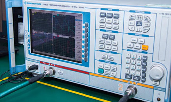
Strict quality inspection builds a solid foundation for electronic component quality.
  1. Visual inspection
  2. Performance testing and reliability verification
  3. Standardized full-process testing
  4. Precise control of every parameter
We eliminate defective components and ensure the stable operation of electronic devices through professional quality standards.

Payment Support

The payment method can be chosen from the methods shown below: Wire Transfer (T/T, Bank Transfer), Western Union, Credit card, PayPal.
  • HKBea
  • Paypal
  • MasterCard
  • Western-Union
  • VISA
Stable Delivery, Sincere Partnership — Your Faithful Supply Chain Partner
  • Efficient Supply Management
  • Cost-Saving Procurement
  • Fast Sourcing & Delivery
Contact us if you have any questions.

Packaging

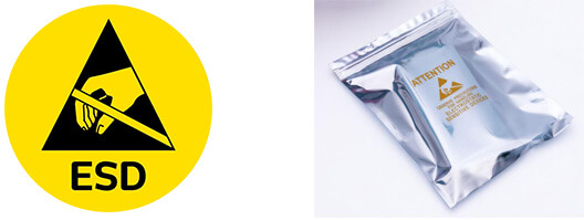
Electrostatic Discharge Protection and Handling

All electrostatic-sensitive components are handled in accordance with electrostatic discharge control procedures. The products are hermetically sealed in anti-static safe packaging to prevent electrostatic damage. Appropriate labeling is also applied for identification and traceability. This ensures product integrity during storage, handling and transportation.


ESD

Certifications & Memberships

Third-party certified, strict quality control. Our certification
  • ISO 9001: 2015
  • ISO 13485: 2016
  • ISO 14001: 2015
  • ISO 28000: 2007
  • ISO 45001: 2018
  • GB/T 27922-2011
  • SMTA
  • IPC
  • ESD
  • PSMA
082.00301.00-RS Image

082.00301.00-RS

Astrodyne TDI
98D-082.00301.00-RS

Want a better price? Add to Cart and Submit RFQ now, we'll contact you immediately.

0 RFQ
Shopping cart (0 Items)
It is empty.
Compare List (0 Items)
It is empty.
Feedback

Your feedback matters! At Allelco, we value the user experience and strive to improve it constantly.
Please share your comments with us via our feedback form, and we'll respond promptly.
Thank you for choosing Allelco.

Subject
E-mail
Comments
Captcha
Drag or click to upload file
Upload File
types: .xls, .xlsx, .doc, .docx, .jpg, .png and .pdf.
Max file size: 10MB