View All

Please refer to the English Version as our Official Version.Return

Europe
France(Français) Germany(Deutsch) Italy(Italia) Russian(русский) Poland(polski) Czech(Čeština) Luxembourg(Lëtzebuergesch) Netherlands(Nederland) Iceland(íslenska) Hungarian(Magyarország) Spain(español) Portugal(Português) Turkey(Türk dili) Bulgaria(Български език) Ukraine(Україна) Greece(Ελλάδα) Israel(עִבְרִית) Sweden(Svenska) Finland(Svenska) Finland(Suomi) Romania(românesc) Moldova(românesc) Slovakia(Slovenská) Denmark(Dansk) Slovenia(Slovenija) Slovenia(Hrvatska) Croatia(Hrvatska) Serbia(Hrvatska) Montenegro(Hrvatska) Bosnia and Herzegovina(Hrvatska) Lithuania(lietuvių) Spain(Português) Switzerland(Deutsch) United Kingdom(English)
Asia/Pacific
Japan(日本語) Korea(한국의) Thailand(ภาษาไทย) Malaysia(Melayu) Singapore(Melayu) Vietnam(Tiếng Việt) Philippines(Pilipino)
Africa, India and Middle East
United Arab Emirates(العربية) Iran(فارسی) Tajikistan(فارسی) India(हिंदी) Madagascar(malaɡasʲ)
South America / Oceania
New Zealand(Maori) Brazil(Português) Angola(Português) Mozambique(Português)
North America
United States(English) Canada(English) Haiti(Ayiti) Mexico(español)
HomeProductsIntegrated Circuits (ICs)Embedded - MicrocontrollersATTINY87-A15SZ
ATTINY87-A15SZ Image
Image may be representation.
See specifications for product details.
EXPRESS OPTION
Payment method

ATTINY87-A15SZ - Atmel

Manufacturer Part Number
ATTINY87-A15SZ
Manufacturer
Atmel
Allelco Part Number
32D-ATTINY87-A15SZ
Warranty
1 Year Allelco Warranty - Find out more
Stock Status:
19,597 pcs available, New & Original
Parts Description
IC MCU 8BIT 8KB FLASH 20SOIC
Package
20-SOIC
Data sheet
-
RoHs Status
 
Our certification
In stock: 19597

Required fields are indicated by an asterisk (*)
Please send RFQ, we will respond immediately.

Quantity

Specifications

ATTINY87-A15SZ Tech Specifications
Atmel - ATTINY87-A15SZ technical specifications, attributes, parameters and parts with similar specifications to Atmel - ATTINY87-A15SZ

Product Attribute Attribute Value
Manufacturer Atmel
Voltage - Supply (Vcc/Vdd) 2.7V ~ 5.5V
Supplier Device Package 20-SOIC
Speed 16MHz
Series Automotive, AEC-Q100, AVR® ATtiny
RAM Size 512 x 8
Program Memory Type FLASH
Program Memory Size 8KB (4K x 16)
Peripherals Brown-out Detect/Reset, POR, PWM, Temp Sensor, WDT
Package / Case 20-SOIC (0.295", 7.50mm Width)
Package Bulk
Product Attribute Attribute Value
Oscillator Type Internal
Operating Temperature -40°C ~ 125°C (TA)
Number of I/O 16
Mounting Type Surface Mount
EEPROM Size 512 x 8
Data Converters A/D 11x10b
Core Size 8-Bit
Core Processor AVR
Connectivity I²C, LINbus, SPI, UART/USART, USI
Base Product Number ATTINY87

Environmental & Export Classifications

ATTRIBUTE DESCRIPTION
ECCN EAR99
HTSUS 8542.31.0001

Parts Introduction

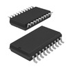
ATTINY87-A15SZ Image
ATTINY87-A15SZ (1)

Manufacturer Part Number

ATTINY87-A15SZ

Manufacturer

microchip-technology

Introduction

The ATTINY87-A15SZ is a high-performance, low-power 8-bit microcontroller from Microchip Technology's AVR® ATtiny series. It features a range of integrated peripherals and flexible configuration options, making it suitable for a variety of embedded applications.

Product Features and Performance

Core Processor: AVR 8-bit

Core Size: 8-Bit

Speed: 16MHz

Connectivity: I2C, LINbus, SPI, UART/USART, USI

Peripherals: Brown-out Detect/Reset, POR, PWM, Temp Sensor, WDT

Number of I/O: 16

Program Memory Size: 8KB (4K x 16)

Program Memory Type: FLASH

EEPROM Size: 512 x 8

RAM Size: 512 x 8

Voltage Supply (Vcc/Vdd): 2.7V ~ 5.5V

Data Converters: A/D 11x10b

Oscillator Type: Internal

Operating Temperature: -40°C ~ 125°C (TA)

Product Advantages

Low-power consumption for battery-powered applications

Flexible peripheral options for customized designs

Robust performance with a wide operating temperature range

Automotive-grade qualification for harsh environments

Key Reasons to Choose This Product

Compact and cost-effective 8-bit microcontroller solution

Extensive peripheral integration for versatile applications

Reliable operation in demanding automotive and industrial environments

Compatibility with the wider AVR® ATtiny series for easy design scalability

Quality and Safety Features

Automotive-grade qualification (AEC-Q100)

Brown-out detection and power-on reset for reliable operation

Compatibility

The ATTINY87-A15SZ is compatible with the broader AVR® ATtiny series, allowing for easy design scalability and migration to alternative models as needed.

Application Areas

Automotive electronics

Industrial control systems

Home automation and smart devices

Portable and battery-powered applications

Product Lifecycle

The ATTINY87-A15SZ is an active product in our website's sales team's portfolio. There are equivalent and alternative models available within the AVR® ATtiny series, such as the ATTINY88, ATTINY167, and ATTINY817. Customers are advised to contact our website's sales team for the most up-to-date information on product availability and recommended alternatives.
Frequently Asked Questions(FAQ)

How does the ATTINY87-A15SZ perform in automotive-grade temperature environments, and what design considerations are needed for long-term reliability?
The ATTINY87-A15SZ is qualified under AEC-Q100 and operates across a -40°C to 125°C ambient temperature range, making it suitable for demanding automotive applications. At full operating temperature extremes, internal oscillator stability may require additional compensation in time-critical functions. Power supply decoupling must be carefully implemented due to increased leakage currents at elevated temperatures. Thermal cycling stress can affect solder joint integrity over time, so proper PCB layout with adequate copper pour and via stitching is recommended for packages exposed to rapid thermal changes common in engine compartments.
What are the trade-offs between using internal versus external clock sources with the ATTINY87-A15SZ when targeting low-power applications?
Using the internal 16MHz oscillator of the ATTINY87-A15SZ reduces component count and simplifies PCB layout but consumes more power compared to lower-frequency internal oscillators or external crystals. For battery-powered systems requiring extended operation, switching to a slower internal clock like 1MHz significantly reduces dynamic current while maintaining peripheral functionality. External crystals provide better timing accuracy but add cost, board space, and susceptibility to mechanical shock—critical factors in automotive vibration environments where the ATTINY87-A15SZ is often deployed.
Can the ATTINY87-A15SZ reliably interface with 3.3V sensors and peripherals when powered from a 5V supply, and what precautions should be taken?
Yes, the ATTINY87-A15SZ supports I/O voltage operation up to VCC + 0.5V, allowing safe interfacing with 3.3V devices even when supplied at 5V. However, bidirectional level shifting is not built-in; direct connection risks exceeding absolute maximum ratings if the 3.3V device drives high during power-up sequencing. Implementing open-drain configurations or discrete MOSFET-based level shifters is advisable. Input thresholds scale with VCC, so logic high recognition from 3.3V inputs remains valid only if the ATTINY87-A15SZ’s VCC exceeds 3.0V.
How much RAM and program memory overhead is typical for implementing a real-time control loop using PID algorithms on the ATTINY87-A15SZ?
An efficient fixed-point PID implementation typically requires approximately 256 bytes of RAM for variables (setpoint, feedback, integral accumulator, gains) and less than 512 bytes of flash. Given the ATTINY87-A15SZ’s 8KB flash and 512-byte SRAM, this leaves sufficient headroom for sensor drivers, communication stacks, and safety monitoring. Flash wear becomes relevant only after tens of thousands of erase/write cycles, which is rarely a concern for firmware updates in production units unless bootloader functionality is used frequently.
What distinguishes the ATTINY87-A15SZ from other ATtiny series MCUs in terms of analog integration and peripheral capabilities?
Compared to earlier ATtiny models, the ATTINY87-A15SZ integrates an enhanced ADC with 10-bit resolution across 11 channels and includes a built-in temperature sensor calibrated against process variations. It also adds USI (Universal Serial Interface) support alongside standard SPI, UART, and I2C, enabling flexible protocol adaptation without hardware changes. These features reduce external component needs in sensor-heavy automotive subsystems such as cabin climate control or lighting modules where space and cost are constrained.
Is it feasible to use the ATTINY87-A15SZ for CAN bus communication, and what alternatives exist given its lack of native CAN support?
The ATTINY87-A15SZ does not include a dedicated CAN controller, so direct CAN bus communication isn’t supported. Instead, an external transceiver like the MCP2515 combined with software bit-banging on one of the GPIO pins can implement basic CAN messaging, though this approach lacks error handling and timing guarantees required by ISO standards. Alternatively, using UART to communicate with a separate CAN-to-UART bridge IC offers greater reliability and compliance with automotive protocols in production designs.
How does the ATTINY87-A15SZ handle brownout detection and reset sequencing during startup in noisy automotive power environments?
The ATTINY87-A15SZ features programmable brownout detection (BOD) thresholds down to 1.8V, which helps prevent erratic behavior during voltage sags common in ignition-on scenarios. During startup, the internal POR circuit ensures a clean reset until VCC stabilizes above the threshold. For robust systems, combining BOD with watchdog timer (WDT) supervision prevents lockup from partial execution states. Proper bulk capacitance near the VCC pin (e.g., 10µF ceramic plus 100nF decoupling) minimizes false resets caused by transient dips.
What considerations apply when selecting pull-up/pull-down resistors for unused I/O pins on the ATTINY87-A15SZ in automotive EMC-sensitive applications?
Unused I/Os on the ATTINY87-A15SZ should be configured as outputs driven to a defined state rather than left floating to avoid floating-node-induced oscillations. Weak internal pull-ups (typically 20–50kΩ) may suffice for slow signals but are insufficient against electrostatic discharge events. In high-noise environments, adding external 10kΩ pulldowns or series termination resistors improves signal integrity. Layout parasitics and connector leakage can create unintended paths, especially in humid conditions, so careful routing adjacent to ground planes mitigates crosstalk.
How does the EEPROM endurance of the ATTINY87-A15SZ compare to flash memory, and what affects write frequency in field-deployed systems?
The ATTINY87-A15SZ’s 512-byte EEPROM has a typical endurance of 100,000 write/erase cycles, vastly outperforming flash memory in rewritability despite lower density. Unlike flash, EEPROM allows byte-level modifications without block erasure, reducing latency and wear. In automotive applications where logging occurs infrequently (e.g., fault codes once per ignition cycle), this enables decades of reliable operation. However, frequent logging without wear-leveling algorithms can lead to premature failure; batching writes or using RAM buffers with periodic flushes is recommended.
What impact does operating frequency have on power consumption when using different sleep modes with the ATTINY87-A15SZ?
Lowering the system clock from 16MHz to 1MHz reduces active current from ~2mA to ~0.5mA at 5V. More significantly, sleep mode current drops dramatically: deep sleep (power-down mode) draws just 0.1µA with RTC enabled. The ATTINY87-A15SZ supports multiple sleep modes (idle, ADC noise reduction, power-save, etc.), each trading wake-up latency for power savings. In battery-backed applications, optimizing wake intervals and disabling unused peripherals before entering sleep yields exponential improvements in runtime—critical for OBD-II diagnostic tools or door modules using the ATTINY87-A15SZ.
Why might the ATTINY87-A15SZ be preferred over larger MCUs in small automotive control units despite its limited memory?
The ATTINY87-A15SZ’s compact 20-SOIC package, wide voltage range (2.7–5.5V), and integrated analog features eliminate need for discrete components in simple actuator or sensor interface tasks. Its low quiescent current and proven AVR core simplify certification for functional safety in non-critical zones of vehicles. When paired with external drivers and sensors, it reduces BOM cost and PCB area compared to microcontrollers with excess peripherals that increase complexity and electromagnetic emissions in cramped automotive layouts.
How should interrupt priority be managed when combining multiple peripherals like ADC, WDT, and USART on the ATTINY87-A15SZ?
The ATTINY87-A15SZ uses a single interrupt vector table with fixed priorities based on peripheral type: reset > external interrupts > timer/counters > USART > ADC > EEPROM write complete. To minimize latency, critical tasks like motor control should rely on dedicated timers rather than polling. Nested interrupts are not supported, so lengthy ISRs (e.g., USART receive) should defer processing via flag checks in main loop. Prioritizing fast-response events ensures deterministic behavior in real-time automotive controls using the ATTINY87-A15SZ.
What role does the built-in temperature sensor play in system health monitoring with the ATTINY87-A15SZ?
The ATTINY87-A15SZ’s on-chip temperature sensor provides relative measurements calibrated to process variations, useful for detecting local hotspots within IC packages. While not accurate for ambient air temperature, it flags potential thermal runaway in power stages or poor heat dissipation scenarios. Readings are accessible via ADC channel 0 and updated every few milliseconds. This feature enables passive cooling strategies or throttling logic without external components, valuable in compact automotive modules where space limits thermistor placement.
Are there known limitations in PWM performance when driving inductive loads directly with the ATTINY87-A15SZ?
The ATTINY87-A15SZ generates PWM signals through general-purpose I/O pins without built-in dead-time generation, making direct drive of inductive loads like solenoids risky. Flyback diodes and external drivers (e.g., N-channel MOSFETs) are mandatory to clamp back-EMF spikes that exceed VCC and damage pins. Additionally, high-side switching requires level-shifting circuitry since gate drive voltages exceed microcontroller output levels. Proper gate resistance tuning balances switching speed and EMI, essential for meeting CISPR 25 standards in automotive audio or lighting systems.
How does the ATTINY87-A15SZ’s LINbus capability differ from full-featured LIN transceivers in automotive networks?
The ATTINY87-A15SZ implements LINbus communication through software using USART or USI, lacking hardware auto-baud and dominant timeout detection found in dedicated LIN transceivers like the TJA1020. This requires precise timing calibration and increases CPU load, limiting scalability in dense networks. While adequate for point-to-point diagnostics or simple slave nodes, it introduces jitter and latency unsuitable for safety-relevant messages. Production systems typically pair the ATTINY87-A15SZ with external LIN transceivers for robustness and compliance.
What precautions are necessary when programming the ATTINY87-A15SZ in high-humidity environments common in tropical automotive deployments?
Moisture ingress can cause intermittent faults during soldering or field servicing due to condensation on unprotected PCBs. Applying conformal coating after assembly protects traces and vias, especially around the 20-SOIC package’s exposed pads. During programming, ensure clean, dry contacts and avoid probing during rainy seasons. If humidity exceeds 85% RH, storage in desiccated bags with silica gel is advised to prevent electrochemical migration, which could create parasitic paths on fine-pitch traces near the ATTINY87-A15SZ’s leads.
How does the ATTINY87-A15SZ support secure firmware updates in production vehicles without compromising bootloader security?
The ATTINY87-A15SZ includes a bootloader area protected by fuse bits, allowing firmware updates via UART or SPI without exposing debug interfaces. However, it lacks cryptographic acceleration or memory protection units, so update authenticity relies on external validation (e.g., checksums or MACs computed off-chip). Secure key storage must reside outside the MCU, increasing complexity. For high-assurance systems, pairing the ATTINY87-A15SZ with a secure element ensures tamper-resistant update chains while maintaining cost efficiency.
What are the implications of using the ATTINY87-A15SZ in ESD-sensitive areas like door handles or roof modules?
Automotive ESD requirements (IEC 61000-4-2 Level 4) demand robust protection beyond the ATTINY87-A15SZ’s human-body model rating of ±2kV. Integrating TVS diodes on all I/O lines and power rails suppresses transient voltages that could latch up internal CMOS structures. Series resistors (100Ω–1kΩ) limit peak current into sensitive nodes. Grounding strategy must include star points near the ATTINY87-A15SZ to avoid ground loops, ensuring ESD energy dissipates safely without damaging the microcontroller in harsh environments.

Parts with Similar Specifications

The three parts on the right have similar specifications to Atmel ATTINY87-A15SZ

Product Attribute ATTINY87-A15SZ ATTINY87-15SZ ATTINY87-A15XZ ATTINY87-15SZ
Part Number ATTINY87-A15SZ ATTINY87-15SZ ATTINY87-A15XZ ATTINY87-15SZ
Manufacturer Microchip Technology Atmel Microchip Technology Microchip Technology
Base Product Number - DAC34H84 MAX500 ADS62P42
Oscillator Type - - - -
Supplier Device Package - 196-NFBGA (12x12) 16-PDIP 64-VQFN (9x9)
RAM Size - - - -
Program Memory Type - - - -
EEPROM Size - - - -
Operating Temperature - -40°C ~ 85°C 0°C ~ 70°C -40°C ~ 85°C
Program Memory Size - - - -
Series - - - -
Core Processor - - - -
Mounting Type - Surface Mount Through Hole Surface Mount
Core Size - - - -
Voltage - Supply (Vcc/Vdd) - - - -
Data Converters - - - -
Number of I/O - - - -
Speed - - - -
Package - Tape & Reel (TR) Tube Tape & Reel (TR)
Peripherals - - - -
Connectivity - - - -
Package / Case - 196-LFBGA 16-DIP (0.300', 7.62mm) 64-VFQFN Exposed Pad

Customer Reviews

Evaluation: 10 Articles

  • ECUb***h
    Sep 22, 2026

    Used for repair of an older automotive ECU. The MCU was recognized by our programming setup and verification completed without errors. The repaired board now starts and communicates normally.

  • RS48***ieldTech
    Sep 16, 2026

    Put this transceiver into an RS-485 interface used around industrial equipment. Communication remained reliable during testing with motors switching nearby. Good result for the replacement board.

  • Logi***b_Chris
    Sep 8, 2026

    Purchased for a Cyclone III development project. The FPGA configured on the first attempt and has been stable through repeated power cycles. No problems with the I/O we are using.

  • Circ***FixerTom
    Sep 2, 2026

    Used this rectifier in a high-current power supply repair. Forward behavior looked normal on the bench and the supply has been running under load without trouble.

  • Retr***UWorks
    Aug 31, 2026

    Needed the exact ST10F269Z2Q6 for servicing an older control unit. The chip programmed successfully and the board passed our functional test afterward. Much easier than redesigning around a newer MCU.

  • Andr***PCBLab
    Aug 28, 2026

    I needed this ADC for an older data acquisition board. Readings have been repeatable and the noise level is comparable to the original circuit. Happy with the purchase.

  • Leat***O'Keefe
    Aug 20, 2026

    one of my hobbies is skydiving. and when i'm skydiving this works great.

  • Ilen***
    Aug 20, 2026

    This product works considerably well. It secretly improves my basketball by a lot.

  • Indu***ialPower
    Aug 17, 2026

    Installed this IGBT module in a power conversion cabinet. Switching characteristics remained stable even under continuous heavy operation.

  • Nikh***ech
    Aug 13, 2026

    Great low-power MCU for portable equipment. Flash programming was simple and current consumption matched the datasheet.

Write a Review

Your Email address will not be published.

Shipment

Delivery Time

In-stock items can be shipped within 24 hours. Some parts will be arranged for delivery within 1-2 days from the date all items arrive at our warehouse. And Allelco ships order once a day at about 17:00, except Sunday. Once the goods are shipped, the estimated delivery time depends on the shipping methods and Delivery destination. The table below shows are the logistic time for some common countries.

Delivery Cost

  1. Use your express account for shipment if you have one.
  2. Use our account for the shipment. Refer to the table below for the approximate charges.
(Different time frame / countries / package size has different price.)

Delivery Method

  1. Global Common Shipment by DHL / UPS / FedEx / TNT / EMS / SF we support.
  2. Others more shipping ways, please get in touch with your customer manager.

Common Countries Logistic Time Reference
Region Country Logistic Time(Day)
America United States 5
Brazil 7
Europe Germany 5
United Kingdom 4
Italy 5
Oceania Australia 6
New Zealand 5
Asia India 4
Japan 4
Middle East Israel 6
DHL & FedEx Shipment Charges Reference
Shipment charges(KG) Reference DHL(USD$)
0.00kg-1.00kg USD$30.00 - USD$60.00
1.00kg-2.00kg USD$40.00 - USD$80.00
2.00kg-3.00kg USD$50.00 - USD$100.00
Note:
The above table is for reference only. There may have some data bias for the uncontrollable factors.
Contact us if you have any questions.
  • QC (Quality Warranty)
  • Payment Support
  • Packaging
  • Certifications & Memberships

QC (Quality Warranty)

Allelco is committed to exceeding customer expectations through customer service excellence, order accuracy, and on-time delivery.
This is achieved through our commitment to the continual improvement of our processes, services, and products.


Strict quality inspection builds a solid foundation for electronic component quality.
  1. Visual inspection
  2. Performance testing and reliability verification
  3. Standardized full-process testing
  4. Precise control of every parameter
We eliminate defective components and ensure the stable operation of electronic devices through professional quality standards.

Payment Support

The payment method can be chosen from the methods shown below: Wire Transfer (T/T, Bank Transfer), Western Union, Credit card, PayPal.
  • HKBea
  • Paypal
  • MasterCard
  • Western-Union
  • VISA
Stable Delivery, Sincere Partnership — Your Faithful Supply Chain Partner
  • Efficient Supply Management
  • Cost-Saving Procurement
  • Fast Sourcing & Delivery
Contact us if you have any questions.

Packaging

Electrostatic Discharge Protection and Handling

All electrostatic-sensitive components are handled in accordance with electrostatic discharge control procedures. The products are hermetically sealed in anti-static safe packaging to prevent electrostatic damage. Appropriate labeling is also applied for identification and traceability. This ensures product integrity during storage, handling and transportation.


ESD

Certifications & Memberships

Third-party certified, strict quality control. Our certification
  • ISO 9001: 2015
  • ISO 13485: 2016
  • ISO 14001: 2015
  • ISO 28000: 2007
  • ISO 45001: 2018
  • GB/T 27922-2011
  • SMTA
  • IPC
  • ESD
  • PSMA
ATTINY87-A15SZ Image

ATTINY87-A15SZ

Atmel
32D-ATTINY87-A15SZ

Want a better price? Add to Cart and Submit RFQ now, we'll contact you immediately.

0 RFQ
Shopping cart (0 Items)
It is empty.
Compare List (0 Items)
It is empty.
Feedback

Your feedback matters! At Allelco, we value the user experience and strive to improve it constantly.
Please share your comments with us via our feedback form, and we'll respond promptly.
Thank you for choosing Allelco.

Subject
E-mail
Comments
Captcha
Drag or click to upload file
Upload File
types: .xls, .xlsx, .doc, .docx, .jpg, .png and .pdf.
Max file size: 10MB