View All

Please refer to the English Version as our Official Version.Return

Europe
France(Français) Germany(Deutsch) Italy(Italia) Russian(русский) Poland(polski) Czech(Čeština) Luxembourg(Lëtzebuergesch) Netherlands(Nederland) Iceland(íslenska) Hungarian(Magyarország) Spain(español) Portugal(Português) Turkey(Türk dili) Bulgaria(Български език) Ukraine(Україна) Greece(Ελλάδα) Israel(עִבְרִית) Sweden(Svenska) Finland(Svenska) Finland(Suomi) Romania(românesc) Moldova(românesc) Slovakia(Slovenská) Denmark(Dansk) Slovenia(Slovenija) Slovenia(Hrvatska) Croatia(Hrvatska) Serbia(Hrvatska) Montenegro(Hrvatska) Bosnia and Herzegovina(Hrvatska) Lithuania(lietuvių) Spain(Português) Switzerland(Deutsch) United Kingdom(English)
Asia/Pacific
Japan(日本語) Korea(한국의) Thailand(ภาษาไทย) Malaysia(Melayu) Singapore(Melayu) Vietnam(Tiếng Việt) Philippines(Pilipino)
Africa, India and Middle East
United Arab Emirates(العربية) Iran(فارسی) Tajikistan(فارسی) India(हिंदी) Madagascar(malaɡasʲ)
South America / Oceania
New Zealand(Maori) Brazil(Português) Angola(Português) Mozambique(Português)
North America
United States(English) Canada(English) Haiti(Ayiti) Mexico(español)
HomeProductsSwitchesRotary SwitchesMB03L1NZGD
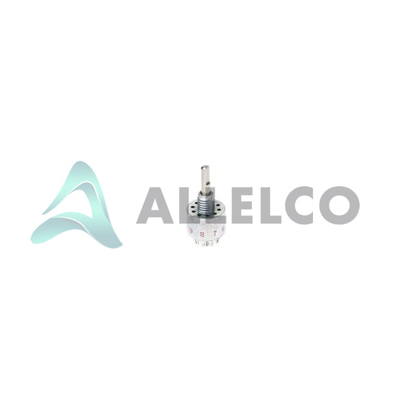
MB03L1NZGD Image
Image may be representation.
See specifications for product details.
EXPRESS OPTION
Payment method

MB03L1NZGD - C&K

Manufacturer Part Number
MB03L1NZGD
Manufacturer
C&K
Allelco Part Number
98D-MB03L1NZGD
Warranty
1 Year Allelco Warranty - Find out more
Stock Status:
41,082 pcs available, New & Original
Parts Description
SWITCH ROTARY 3POS 250MA 125V
Package
Tray
Data sheet
MB03L1NZGD.pdf
RoHs Status
ROHS3 Compliant
Our certification
In stock: 41082
  • Unit Price: $24.13
  • Subtotal: $0.00

Want a better price?
Add to Cart and Submit RFQ now, we'll contact you immediately.

Quantity Unit Price Ext. Price
1+ $24.13 $24.13
The above prices does not include taxes and freight rates, which will be calculated on the order pages.


Specifications

MB03L1NZGD Tech Specifications
C&K - MB03L1NZGD technical specifications, attributes, parameters and parts with similar specifications to C&K - MB03L1NZGD

Product Attribute Attribute Value
Manufacturer C&K
Voltage Rating - DC 28 V
Voltage Rating - AC 125 V
Termination Style Solder Lug
Series M
Panel Cutout Dimensions Circular - 6.60mm Dia
Package Tray
Number of Positions 3
Number of Poles per Deck 2
Number of Decks 1
Mounting Type Panel Mount
Index Stops Fixed
Product Attribute Attribute Value
Features -
Depth Behind Panel 14.86mm
Current Rating (Amps) 250mA (AC/DC)
Contact Timing Non-Shorting (BBM)
Contact Material Copper Alloy
Contact Finish Gold
Circuit per Deck DP3T
Base Product Number MB03L1N
Angle of Throw 36°
Actuator Type Flatted (3.17mm Dia)
Actuator Length 10.16mm

Environmental & Export Classifications

ATTRIBUTE DESCRIPTION
RoHs Status ROHS3 Compliant
Moisture Sensitivity Level (MSL) 1 (Unlimited)
REACH Status REACH Unaffected
ECCN EAR99
HTSUS 8536.50.9020

Frequently Asked Questions(FAQ)

What are the key differences between the MB03L1NZGD rotary switch and a comparable 2-position model for panel-mounted applications?
The MB03L1NZGD provides three fixed index stops with DP3T (Double Pole, Three Throw) switching capability, allowing independent control of two separate circuits across three distinct positions. This architecture differs fundamentally from 2-position models: while a 2-position switch handles binary state transitions, the MB03L1NZGD enables three-state logic or multi-mode operation (e.g., Off-Low-High or Mode A-Mode B-Mode C). The 36° angle of throw on the MB03L1NZGD creates deliberate mechanical detents between positions, reducing unintended state changes during mechanical vibration compared to continuous-rotation alternatives. For applications requiring mode selection or independent relay control across three operating conditions, the MB03L1NZGD's fixed positioning and dual-deck architecture provide deterministic switching without requiring external position feedback.
Can the MB03L1NZGD handle both AC and DC loads, and what voltage derating should be applied when switching mixed-voltage circuits?
The MB03L1NZGD is rated for 250mA at 125V AC or 28V DC, with contact material (copper alloy with gold finish) designed to manage both AC and DC switching. However, the voltage ratings are independent specifications: AC and DC loads must not be combined within the same circuit or deck. DC switching generally produces more severe contact erosion than equivalent AC switching due to absence of zero-crossing extinction, meaning sustained DC loads at or near the 28V DC limit will degrade contact resistance faster than equivalent AC operation at 125V. When designing mixed-voltage systems using the MB03L1NZGD, separate the AC circuits (up to 125V) and DC circuits (up to 28V) into different pole pairs. If a single deck must handle variable loads, derate by approximately 20% below the stated 250mA continuous rating to account for contact wear margin, particularly when DC switching frequency exceeds 10 cycles per minute.
What does 'Non-Shorting (BBM)' contact timing mean for the MB03L1NZGD, and how does this affect circuit sequencing during position transitions?
Non-Shorting (BBM—'Before-Break-Make' or 'Break-Before-Make') contact timing on the MB03L1NZGD means the existing contact pair opens before the next contact pair closes as the actuator rotates between positions. This prevents momentary short-circuit conditions between adjacent throw positions and eliminates destructive contact bounce during transitions. For inductive loads (relays, solenoids), the MB03L1NZGD's break-before-make action prevents back-EMF transients from arcing between throw positions, protecting downstream logic circuits from induced noise. The trade-off is a brief interval (typically 2–5ms depending on actuator speed) where the circuit is open during the throw transition. Applications sensitive to signal continuity—such as audio routing or data multiplexing—must account for this momentary break. Conversely, power-switching applications benefit from non-shorting behavior because it eliminates cross-position current paths that could cause logic errors or component damage.
How should the panel cutout dimensions be specified for the MB03L1NZGD to ensure proper sealing and mechanical stability in environmental enclosures?
The MB03L1NZGD requires a circular panel cutout of 6.60mm diameter, with depth-behind-panel clearance of 14.86mm to accommodate the switch body and solder lug terminations. When mounting the MB03L1NZGD in weatherproof or sealed enclosures, the cutout diameter should be held to 6.60mm ±0.10mm to minimize radial clearance around the flatted actuator shaft (3.17mm diameter). Excessive clearance allows moisture and contaminant ingress around the shaft seal, while undersized cutouts force over-torquing during installation, potentially cracking the plastic actuator stem. The panel thickness should not exceed 3.2mm; thicker panels reduce actuator throw engagement and increase mechanical play. For applications requiring IP67 or higher environmental protection, pair the MB03L1NZGD with a compatible panel seal gasket (typically silicone or EPDM, 6.8mm OD) positioned between the switch flange and panel surface. The solder lug terminations should clear the panel rear by at least 8mm to prevent solder joint stress during component insertion and to accommodate standard PCB standoff heights.
What is the mechanical life expectancy of the MB03L1NZGD rotary switch under continuous cycling, and how does contact material affect degradation rates?
The MB03L1NZGD, with copper-alloy contacts finished in gold, typically exhibits mechanical life of 10,000–50,000 cycles depending on load current, switching frequency, and actuator force profile. At rated current (250mA), expect approximately 20,000 cycles before measurable contact resistance increase (defined as <100mΩ rise from initial state). The gold finish provides corrosion resistance and low contact resistance but is relatively soft; heavy mechanical shock or over-torquing the actuator can accelerate wear by creating surface abrasion that exposes base copper underneath. Switching frequency has a non-linear effect: intermittent operation (1–5 cycles per day) allows contact self-healing through oxidation cycles, whereas continuous cycling (>100 cycles per hour) produces cumulative thermal stress and accelerates copper migration. For applications with switching rates >50 cycles per hour, derating to 180mA per circuit reduces thermal load and extends cycle life by approximately 40%. In dry environments (RH <30%), the MB03L1NZGD achieves upper end of cycle life; in humid conditions, contact resistance drifts more rapidly even below maximum current, requiring periodic contact cleaning or replacement at 15,000-cycle intervals.
How does the MB03L1NZGD compare to a solenoid-actuated selector switch for applications requiring remote or automated position switching?
The MB03L1NZGD is a manually actuated rotary switch with mechanical positioning via the 3.17mm flatted shaft, whereas solenoid-actuated alternatives require external control voltage and consume power to maintain position. For manual console or panel-mounted applications, the MB03L1NZGD eliminates control logic and power supply dependencies, reducing circuit complexity and cost. However, the MB03L1NZGD cannot provide remote position switching or automated sequencing without mechanical linkage mechanisms. Solenoid selectors offer feedback and multi-position sequencing but introduce electromagnetic noise, require higher control currents, and demand mechanical hysteresis tuning to prevent chatter. The MB03L1NZGD's fixed 36° detent angle and 10.16mm actuator length define positive mechanical stops that do not drift; solenoid switches require electrical feedback (limit switches or resolvers) to confirm position. For applications demanding both manual override and automated control, a hybrid approach—using the MB03L1NZGD in combination with a separate solenoid clutch mechanism—provides the deterministic positioning of the MB03L1NZGD with the automation flexibility of electromechanical actuation.
What precautions are necessary when solder-lugging the MB03L1NZGD into high-current applications to prevent thermal stress and joint fatigue?
The MB03L1NZGD's solder lug termination (not breadboard-compatible) requires careful thermal management during PCB assembly and throughout the operating lifetime. At 250mA per pole, steady-state I²R heating in the lug and lead can reach 15–25°C above ambient, especially in compact layouts where airflow is restricted. Solder lugs should be attached to copper PCB traces of at least 2 oz (70µm) thickness to distribute heat and reduce lug temperature rise; single-layer or thin-foil substrates can cause solder joint degradation (creep) within 500–2000 operating hours. Use lead-free solder (SAC305 minimum) with thermal cycling simulation (IPC-9701 test conditions) to verify joint reliability, particularly if the MB03L1NZGD will experience temperature excursions from -10°C to +60°C or greater. Mechanically strain-relieve the lug by routing the connected trace away from the switch body at an angle >45° to the lug axis; this reduces flexing-induced fatigue at the solder joint. For high-vibration environments (automotive, industrial machinery), encapsulate the solder joint in epoxy potting compound to dampen mechanical motion; unencapsulated joints in vibration-exposed applications typically fail within 3–5 years of operation.
Is the MB03L1NZGD suitable for low-signal switching applications (milliamp or sub-amp levels), and what contact resistance specification should be verified?
The MB03L1NZGD is rated for 250mA minimum operating current on the AC side and 28V DC, making it a power-switching component rather than a signal-level switch. Operation below approximately 50mA can result in incomplete wetting of gold-plated contacts, leading to erratic resistance behavior (50–500mΩ intermittent spikes) when switching low-level analog signals or sensitive logic inputs. The MB03L1NZGD is not recommended for audio-frequency signal routing, low-level DC bias switching, or precision analog multiplexing applications. If application requirements demand low-current operation, verify contact resistance specification at actual operating current (not rated current) from the manufacturer; the MB03L1NZGD's datasheet typically guarantees <50mΩ contact resistance only when conducting within the 100–250mA range. For milliamp-level switching, consider alternative low-level rocker or toggle switches with thinner gold plating and softer contact geometry designed for signal-level loads. If the MB03L1NZGD must be used below rated current, operate at minimum 20mA per circuit and include series isolation diodes to prevent reverse bias damage to downstream logic gates.
What are the RoHS and environmental compliance implications of the MB03L1NZGD for medical device and aerospace applications?
The MB03L1NZGD carries RoHS3 compliance, meaning lead, cadmium, and other priority restricted substances meet EU Directive 2011/65/EU limits. However, RoHS3 compliance does not automatically qualify the component for medical device (MDD/MDR) or aerospace (AS9100) supply chains, which impose additional material traceability, supplier auditing, and design documentation requirements. The MB03L1NZGD's REACH status is 'REACH Unaffected,' indicating the component is not subject to REACH Substance of Very High Concern (SVHC) restrictions, but this does not guarantee exemption from medical device biocompatibility testing (ISO 10993 series) or aerospace counterfeit-prevention protocols. For aerospace applications, the MB03L1NZGD requires distributor traceability certification (AS9120B) and design approval per MIL-SPEC or equivalent industrial standard; standard commercial-grade MB03L1NZGD units do not inherently meet these requirements. Medical device applications using the MB03L1NZGD must document material composition (particularly contact material, finish, and insulation polymers) and perform biocompatibility assessment if the switch contacts surface area exposure exceeds category thresholds. Consult the original manufacturer's compliance data sheets and qualify the specific MB03L1NZGD lot against application-specific standards before design commitment.
How does the MB03L1NZGD's 10.16mm flatted actuator interact with different knob and coupling designs, and what are common mechanical mismatches?
The MB03L1NZGD's actuator is a flatted shaft 3.17mm in diameter and 10.16mm in length, designed to mate with panel-mounted knobs or levers via D-shaped or flatted-bore couplings. Standard metric 3mm flatted-bore knobs fit the MB03L1NZGD with minimal radial play; however, many OEM knob suppliers source imperial-spec (0.125 inch) bores, which at 3.18mm are slightly oversized and can introduce up to 0.15mm radial wobble. This clearance causes tactile detent inconsistency, particularly noticeable when transitioning between position 1 and position 3 (maximum lever arm rotation). The 10.16mm actuator length limits knob design depth; most commercial knobs are 8–12mm deep with 4–5mm bore engagement, leaving only 5–6mm of shaft protrusion for knob friction grip. Over-tightening the knob setscrew can deform the flatted surfaces, increasing rotational friction and eventually seizing the actuator. For robust mechanical coupling, specify knobs with metric 3.17mm (±0.05mm) D-shaped bores and hardened steel set screws torqued to 0.5–1.0 N⋅m (not finger-tight). Molded plastic knobs degrade rapidly under repeated torque cycling and are not recommended for applications >1000 cycles per year; aluminum or brass knobs with hardened bore liners provide superior durability and consistent detent feel over the MB03L1NZGD's lifecycle.
What electrical noise or EMI characteristics should be anticipated when the MB03L1NZGD switches inductive loads, and what filtering or snubbing approaches are effective?
The MB03L1NZGD's break-before-make contact action creates a brief open-circuit condition during position transitions; when switching inductive loads (relays, solenoids, motor windings), the collapsing magnetic field generates high-voltage transients (typically 20–100V spikes) across the open contact gap. These transients radiate broadband EMI spanning 100kHz to >10MHz, potentially corrupting nearby analog signals or triggering false logic states in microcontroller inputs. RC snubbing (typical 100Ω + 0.1µF across the load) attenuates high-frequency transients but introduces phase shift that can delay contact opening slightly. Diode clamping (freewheeling diode across inductive load) eliminates positive transients but allows negative-going oscillations if the MB03L1NZGD's DC rating is exceeded. For robust EMI suppression, use varistor or transient suppression diode (1N4007 or equivalent TVS) rated for peak transient energy >50µJ; this combination clamps transients to <30V and reduces EMI by 15–20dB across the problematic frequency band. Cable routing becomes critical: keep signal wiring at least 15cm away from MB03L1NZGD control leads, and use shielded twisted-pair for logic control signals referenced to the same ground plane. At 125V AC switching, conducted EMI is also present on the AC mains; for grid-connected applications, incorporate a 0.47µF X2-rated capacitor across the MB03L1NZGD load to suppress differential-mode noise per IEC 60939 guidelines.
Can the MB03L1NZGD be modified or reworked after PCB assembly, and what repair procedures preserve component integrity?
The MB03L1NZGD's solder-lug termination permits desoldering and rework if performed with temperature-controlled equipment and careful mechanical handling. Standard PCB rework stations (hand iron, hot-air rework tools) can remove and reattach the MB03L1NZGD within 3–4 thermal cycles before contact resistance degradation becomes measurable (typically after 8–10 cycles). The flatted actuator shaft is susceptible to thermal warping if peak reflow temperature exceeds 260°C; lead-free soldering profiles should not exceed 245°C peak, and the MB03L1NZGD body must remain >5°C below peak temperature during cooling to prevent permanent plastic deformation. Mechanical stress on solder lugs during removal (prying, lever extraction) can crack the internal contact spring, rendering the MB03L1NZGD non-functional even if electrical continuity appears intact under DC testing. Recommended rework procedure: (1) apply heat-resistant silicone conformal coating around the actuator to protect from thermal shock, (2) use dual soldering tips or hot-air tool set to 240–245°C, (3) apply flux to lug pads 30 seconds before desoldering to allow solder wetting, (4) remove lugs vertically using minimal mechanical force, (5) allow 10-minute cool-down before reinsertion, (6) verify actuator rotation smoothness (should require 0.3–0.5 N⋅m torque) after rework. Lugs bent or cracked during removal cannot be reliably repaired; replace the entire MB03L1NZGD unit rather than attempting solder-bridge repair.
What thermal and moisture considerations apply to the MB03L1NZGD in sealed enclosures or potted assemblies, and how does MSL1 rating affect storage and field reliability?
The MB03L1NZGD carries Moisture Sensitivity Level (MSL) 1, indicating unlimited moisture sensitivity tolerance—the component does not require dry-pack shipping or bake-out procedures before assembly, unlike higher MSL components. However, MSL1 does not mean the MB03L1NZGD is impervious to moisture; it means the component can tolerate moisture absorption without immediate delamination or popcorning failures. In sealed enclosures or potted assemblies, moisture can still penetrate the switch body through the actuator shaft interface, particularly in cyclic temperature environments where thermal expansion creates breathing paths. After potting, internal condensation forms at the contact surfaces during thermal cycling, causing gradual contact resistance increase and contact corrosion over 2–5 years. To mitigate moisture ingress in potted assemblies: (1) use penetrating potting compound (epoxy or polyurethane, not rigid acrylic) that flows around the MB03L1NZGD and creates a continuous moisture barrier, (2) apply conformal coating (acrylic or urethane) to the MB03L1NZGD before potting to seal the actuator shaft interface, (3) incorporate silica gel desiccant packs inside sealed enclosures to maintain relative humidity <30%, (4) maintain operational temperature between 10–50°C to minimize condensation risk. Field reliability in high-humidity environments (>80% RH) shows 30–50% reduction in median time between failures compared to dry environments; this degradation is cumulative and non-reversible.
How should the MB03L1NZGD be specified in design documentation and schematic representation to ensure manufacturing and assembly clarity?
The MB03L1NZGD must be represented in electrical schematics as a 3-position DP3T rotary switch with clearly labeled pole pairs (P1A/P1B and P2A/P2B) and throw positions (1, 2, 3 or Off-Low-High, depending on application function). The schematic symbol should use a rotary-specific icon (arc with position indicator) rather than generic toggle symbols to signal manufacturing that a specific actuator profile and detent mechanism are required. In the Bill of Materials (BOM), the full part number MB03L1NZGD must be included with manufacturer 'C&K' and specification of RoHS3 compliance status. Assembly drawings must annotate the panel cutout as 6.60mm diameter circular, depth-behind-panel as 14.86mm minimum, and specify actuator orientation (knob indicator mark aligned to position 1, for example). Mechanical documentation should note solder-lug termination (not breadboard-compatible) and specify PCB trace gauge (minimum 2 oz copper) and strain relief routing. In production BOM notes, flag the MB03L1NZGD as a manual actuator component requiring human assembly verification—automated pick-and-place equipment cannot confirm proper detent function. Design reviews should cross-reference the MB03L1NZGD's electrical ratings (250mA, 125V AC / 28V DC) against circuit load calculations and specify required snubbing or transient suppression if inductive loads are present, ensuring manufacturing and quality teams understand the component's role and constraints before production release.

Parts with Similar Specifications

The three parts on the right have similar specifications to C&K MB03L1NZGD

Product Attribute MB03L1NZQD MB03L1NCGD MB03L2NZGD MB03L1NZGF
Part Number MB03L1NZQD MB03L1NCGD MB03L2NZGD MB03L1NZGF
Manufacturer C&K C&K C&K C&K
Circuit per Deck - - - -
Angle of Throw - - - -
Mounting Type - Surface Mount Through Hole Surface Mount
Actuator Type - - - -
Termination Style - - - -
Current Rating (Amps) - - - -
Number of Decks - - - -
Number of Poles per Deck - - - -
Contact Timing - - - -
Index Stops - - - -
Actuator Length - - - -
Base Product Number - DAC34H84 MAX500 ADS62P42
Voltage Rating - DC - - - -
Package - Tape & Reel (TR) Tube Tape & Reel (TR)
Features - - - Simultaneous Sampling
Contact Finish - - - -
Contact Material - - - -
Series - - - -
Panel Cutout Dimensions - - - -
Depth Behind Panel - - - -
Number of Positions - - - -
Voltage Rating - AC - - - -

MB03L1NZGD Datasheet PDF

Download MB03L1NZGD pdf datasheets and C&K documentation for MB03L1NZGD - C&K.

Datasheets
M Series Datasheet.pdf
PCN Design/Specification
M Series Rotary - process improvement 28/APR/2021.pdf
PCN Assembly/Origin
Multiple Devices Location 04/Sep/2019.pdf
Environmental Information
C&K RoHS/REACH.pdf

Customer Reviews

Evaluation: 10 Articles

  • ECUb***h
    Sep 22, 2026

    Used for repair of an older automotive ECU. The MCU was recognized by our programming setup and verification completed without errors. The repaired board now starts and communicates normally.

  • RS48***ieldTech
    Sep 16, 2026

    Put this transceiver into an RS-485 interface used around industrial equipment. Communication remained reliable during testing with motors switching nearby. Good result for the replacement board.

  • Logi***b_Chris
    Sep 8, 2026

    Purchased for a Cyclone III development project. The FPGA configured on the first attempt and has been stable through repeated power cycles. No problems with the I/O we are using.

  • Circ***FixerTom
    Sep 2, 2026

    Used this rectifier in a high-current power supply repair. Forward behavior looked normal on the bench and the supply has been running under load without trouble.

  • Retr***UWorks
    Aug 31, 2026

    Needed the exact ST10F269Z2Q6 for servicing an older control unit. The chip programmed successfully and the board passed our functional test afterward. Much easier than redesigning around a newer MCU.

  • Andr***PCBLab
    Aug 28, 2026

    I needed this ADC for an older data acquisition board. Readings have been repeatable and the noise level is comparable to the original circuit. Happy with the purchase.

  • Leat***O'Keefe
    Aug 20, 2026

    one of my hobbies is skydiving. and when i'm skydiving this works great.

  • Ilen***
    Aug 20, 2026

    This product works considerably well. It secretly improves my basketball by a lot.

  • Indu***ialPower
    Aug 17, 2026

    Installed this IGBT module in a power conversion cabinet. Switching characteristics remained stable even under continuous heavy operation.

  • Nikh***ech
    Aug 13, 2026

    Great low-power MCU for portable equipment. Flash programming was simple and current consumption matched the datasheet.

Write a Review

Your Email address will not be published.

Shipment

Delivery Time

In-stock items can be shipped within 24 hours. Some parts will be arranged for delivery within 1-2 days from the date all items arrive at our warehouse. And Allelco ships order once a day at about 17:00, except Sunday. Once the goods are shipped, the estimated delivery time depends on the shipping methods and Delivery destination. The table below shows are the logistic time for some common countries.

Delivery Cost

  1. Use your express account for shipment if you have one.
  2. Use our account for the shipment. Refer to the table below for the approximate charges.
(Different time frame / countries / package size has different price.)

Delivery Method

  1. Global Common Shipment by DHL / UPS / FedEx / TNT / EMS / SF we support.
  2. Others more shipping ways, please get in touch with your customer manager.

Common Countries Logistic Time Reference
Region Country Logistic Time(Day)
America United States 5
Brazil 7
Europe Germany 5
United Kingdom 4
Italy 5
Oceania Australia 6
New Zealand 5
Asia India 4
Japan 4
Middle East Israel 6
DHL & FedEx Shipment Charges Reference
Shipment charges(KG) Reference DHL(USD$)
0.00kg-1.00kg USD$30.00 - USD$60.00
1.00kg-2.00kg USD$40.00 - USD$80.00
2.00kg-3.00kg USD$50.00 - USD$100.00
Note:
The above table is for reference only. There may have some data bias for the uncontrollable factors.
Contact us if you have any questions.
  • QC (Quality Warranty)
  • Payment Support
  • Packaging
  • Certifications & Memberships

QC (Quality Warranty)

Allelco is committed to exceeding customer expectations through customer service excellence, order accuracy, and on-time delivery.
This is achieved through our commitment to the continual improvement of our processes, services, and products.


Strict quality inspection builds a solid foundation for electronic component quality.
  1. Visual inspection
  2. Performance testing and reliability verification
  3. Standardized full-process testing
  4. Precise control of every parameter
We eliminate defective components and ensure the stable operation of electronic devices through professional quality standards.

Payment Support

The payment method can be chosen from the methods shown below: Wire Transfer (T/T, Bank Transfer), Western Union, Credit card, PayPal.
  • HKBea
  • Paypal
  • MasterCard
  • Western-Union
  • VISA
Stable Delivery, Sincere Partnership — Your Faithful Supply Chain Partner
  • Efficient Supply Management
  • Cost-Saving Procurement
  • Fast Sourcing & Delivery
Contact us if you have any questions.

Packaging

Electrostatic Discharge Protection and Handling

All electrostatic-sensitive components are handled in accordance with electrostatic discharge control procedures. The products are hermetically sealed in anti-static safe packaging to prevent electrostatic damage. Appropriate labeling is also applied for identification and traceability. This ensures product integrity during storage, handling and transportation.


ESD

Certifications & Memberships

Third-party certified, strict quality control. Our certification
  • ISO 9001: 2015
  • ISO 13485: 2016
  • ISO 14001: 2015
  • ISO 28000: 2007
  • ISO 45001: 2018
  • GB/T 27922-2011
  • SMTA
  • IPC
  • ESD
  • PSMA
MB03L1NZGD Image

MB03L1NZGD

C&K
98D-MB03L1NZGD

Want a better price? Add to Cart and Submit RFQ now, we'll contact you immediately.

0 RFQ
Shopping cart (0 Items)
It is empty.
Compare List (0 Items)
It is empty.
Feedback

Your feedback matters! At Allelco, we value the user experience and strive to improve it constantly.
Please share your comments with us via our feedback form, and we'll respond promptly.
Thank you for choosing Allelco.

Subject
E-mail
Comments
Captcha
Drag or click to upload file
Upload File
types: .xls, .xlsx, .doc, .docx, .jpg, .png and .pdf.
Max file size: 10MB