View All

Please refer to the English Version as our Official Version.Return

Europe
France(Français) Germany(Deutsch) Italy(Italia) Russian(русский) Poland(polski) Czech(Čeština) Luxembourg(Lëtzebuergesch) Netherlands(Nederland) Iceland(íslenska) Hungarian(Magyarország) Spain(español) Portugal(Português) Turkey(Türk dili) Bulgaria(Български език) Ukraine(Україна) Greece(Ελλάδα) Israel(עִבְרִית) Sweden(Svenska) Finland(Svenska) Finland(Suomi) Romania(românesc) Moldova(românesc) Slovakia(Slovenská) Denmark(Dansk) Slovenia(Slovenija) Slovenia(Hrvatska) Croatia(Hrvatska) Serbia(Hrvatska) Montenegro(Hrvatska) Bosnia and Herzegovina(Hrvatska) Lithuania(lietuvių) Spain(Português) Switzerland(Deutsch) United Kingdom(English)
Asia/Pacific
Japan(日本語) Korea(한국의) Thailand(ภาษาไทย) Malaysia(Melayu) Singapore(Melayu) Vietnam(Tiếng Việt) Philippines(Pilipino)
Africa, India and Middle East
United Arab Emirates(العربية) Iran(فارسی) Tajikistan(فارسی) India(हिंदी) Madagascar(malaɡasʲ)
South America / Oceania
New Zealand(Maori) Brazil(Português) Angola(Português) Mozambique(Português)
North America
United States(English) Canada(English) Haiti(Ayiti) Mexico(español)
HomeProductsSwitchesRocker SwitchesU413J2ZQE2
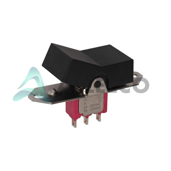
U413J2ZQE2 Image
Image may be representation.
See specifications for product details.
EXPRESS OPTION
Payment method

U413J2ZQE2 - C&K

Manufacturer Part Number
U413J2ZQE2
Manufacturer
C&K
Allelco Part Number
98D-U413J2ZQE2
Warranty
1 Year Allelco Warranty - Find out more
Stock Status:
45,337 pcs available, New & Original
Parts Description
SWITCH ROCKER DP3T 5A 120V
Package
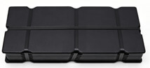
Tray
Data sheet
U413J2ZQE2.pdf
RoHs Status
ROHS3 Compliant
Our certification
In stock: 45337
  • Unit Price: $21.624
  • Subtotal: $0.00

Want a better price?
Add to Cart and Submit RFQ now, we'll contact you immediately.

Quantity Unit Price Ext. Price
1+ $21.624 $21.62
The above prices does not include taxes and freight rates, which will be calculated on the order pages.


Specifications

U413J2ZQE2 Tech Specifications
C&K - U413J2ZQE2 technical specifications, attributes, parameters and parts with similar specifications to C&K - U413J2ZQE2

Product Attribute Attribute Value
Manufacturer C&K
Voltage Rating - DC 28 V
Voltage Rating - AC 120 V
Termination Style Solder Lug
Switch Function On-On-Mom
Series 7000
Panel Cutout Dimensions Rectangular - 17.96mm x 10.62mm
Package Tray
Operating Temperature -30°C ~ 85°C
Mounting Type Panel Mount, Flange
Mechanical Life -
Product Attribute Attribute Value
Ingress Protection -
Illumination Voltage (Nominal) -
Illumination Type, Color -
Features Jumper needed to achieve triple throw
Electrical Life 40,000 Cycles
Current Rating (Amps) 5A (AC/DC)
Color - Actuator/Cap Black
Circuit DP3T
Base Product Number U413J2
Actuator Type Paddle
Actuator Marking No Marking

Environmental & Export Classifications

ATTRIBUTE DESCRIPTION
RoHs Status ROHS3 Compliant
Moisture Sensitivity Level (MSL) 1 (Unlimited)
REACH Status REACH Affected
ECCN EAR99
HTSUS 8536.50.9065

Frequently Asked Questions(FAQ)

What is the actual switching capacity difference between the U413J2ZQE2 DP3T rocker switch at 120V AC versus 28V DC ratings?
The U413J2ZQE2 is rated for 5A at 120V AC or 28V DC, but these represent different power dissipation scenarios. At 120V AC, the switch can handle 600VA, while at 28V DC, the same 5A current represents only 140W. This difference matters in industrial applications where AC line voltage switching (typical in factory automation) involves higher voltage stress across contacts, whereas 28V DC switching (common in aviation and marine systems) prioritizes current capacity over voltage breakdown risk. The voltage rating reflects the dielectric strength required to prevent arcing across open contacts.
Can the U413J2ZQE2 rocker switch replace a standard DP3T toggle switch in an existing panel without layout modification?
The U413J2ZQE2 requires a rectangular panel cutout of 17.96mm × 10.62mm with flange-mount installation, which differs from standard round toggle cutouts. Many existing panels use 0.625-inch (15.88mm) or larger round holes. The U413J2ZQE2's rectangular requirement means direct substitution is not possible without drilling a new cutout or using an adapter plate. Additionally, the U413J2ZQE2 uses solder lug termination rather than threaded studs, requiring circuit board or wiring harness redesign. Panel retrofit with this model is feasible only if the enclosure design accommodates rectangular openings.
Why does the U413J2ZQE2 DP3T require a jumper wire to achieve triple-throw operation, and what are the circuit implications?
The U413J2ZQE2 DP3T configuration lists 'Jumper needed to achieve triple throw' as a feature constraint. This indicates the switch mechanism internally supports three positions, but the contact wiring from the solder lugs requires an external jumper connection to enable the third position electrically. Without the jumper, the switch functions as a DP2T (double-pole double-throw). This design reduces pin count and assembly cost but shifts configuration responsibility to the system integrator. Ensure the jumper installation is documented in assembly work instructions; omitting it results in loss of one switching mode.
How does the 40,000-cycle electrical life rating of the U413J2ZQE2 compare to typical duty cycles in industrial control applications?
The U413J2ZQE2 specifies 40,000 electrical cycles at rated load (5A, 120V). In industrial environments, a machine operator toggling a control switch 10 times per shift over 250 working days annually generates approximately 5,000 cycles per year. At this pace, the U413J2ZQE2 would reach end-of-life in approximately 8 years. However, rapid-cycling applications (such as automated self-test sequences or high-frequency mode switching) can exhaust the 40,000-cycle budget in months. For safety-critical circuits or high-duty-cycle installations, specify a mechanical-life rating from the manufacturer or implement switch redundancy.
What thermal and environmental limits should be considered when installing the U413J2ZQE2 in outdoor or temperature-extreme enclosures?
The U413J2ZQE2 operates within -30°C to 85°C, which covers most industrial environments but excludes deep-freeze storage (-40°C) and high-temperature process environments (>85°C). In outdoor installations, the switch contacts can experience contact resistance drift at temperature extremes; at -30°C, contact resistance may increase by 15–25% due to reduced contact pressure and material contraction. At 85°C, thermal cycling stress on solder lugs can fatigue the connection over time. The switch carries no ingress protection rating, so outdoor use requires an additional weatherproof enclosure. For harsh environments, confirm cULus approval is valid in your jurisdiction and verify that solder-lug connections are potted or strain-relieved to prevent vibration-induced failure.
How should the U413J2ZQE2 be wired to safely switch inductive loads such as solenoids or motor starters?
The U413J2ZQE2 is rated for 5A resistive load at 120V but does not specify inductive-load derating. When switching inductive loads (solenoids, relay coils, small motor windings), inductive kick-back can generate voltage spikes 5–10 times the nominal 120V, causing arcing across the U413J2ZQE2 contacts and premature failure. Always install a diode (1N4007 or equivalent) across DC inductive loads and a snubber network (resistor-capacitor or varistor) across AC loads. For high-inrush solenoids, reduce the effective load current by using the U413J2ZQE2 to switch a relay coil instead of the solenoid directly. This isolates the U413J2ZQE2 from inductive transients and extends switch life beyond the 40,000-cycle rating.
Is the U413J2ZQE2 suitable for low-signal switching applications, such as audio or data line control?
The U413J2ZQE2 is a power switch optimized for 5A loads at 120V and is not rated for low-signal or analog switching. Contact resistance is specified only for rated loads (5A); at milliamp-level signal currents, contact oxide films may not be broken through, resulting in unpredictable contact resistance (10–100+ ohms) and signal distortion. Additionally, the switch mechanism introduces mechanical contact bounce (typically 10–50ms), unsuitable for digital data or audio signals. For signal-level switching, use a dedicated analog switch IC or electromechanical relay with specified low-level contact ratings (rated to handle sub-amp currents and millivolt signals).
What is the solder-lug termination method on the U413J2ZQE2, and how should it be integrated into a circuit board layout?
The U413J2ZQE2 uses solder lugs (also called solder tags or terminals) for connection, which are flat metal tabs designed to be inserted into plated holes on a PCB or wired harness and then wave-soldered or hand-soldered. Solder lugs require 0.062-inch (1.57mm) or larger diameter holes depending on lug width. Unlike threaded studs or connectors, solder lugs create a permanent joint and are difficult to remove or reposition after soldering. In PCB design, allocate generous solder pad area (minimum 0.25 inches) around each lug hole to ensure solder wetting and mechanical strength. Use thermal relief to avoid excessive heat sink effects. Verify that solder-lug spacing matches your board's trace routing to avoid layout conflicts, especially given the U413J2ZQE2's 17.96mm × 10.62mm footprint.
How does the cULus approval of the U413J2ZQE2 affect its use in North American versus international markets?
The cULus marking indicates the U413J2ZQE2 is listed by UL (Underwriters Laboratories) for both Canadian and U.S. markets under UL 60947-3 (industrial control switches) standards. This approval covers the electrical and mechanical safety of the switch itself but does not extend to your end application. In North America, cULus approval supports equipment certification but does not eliminate the requirement for your system to undergo its own UL/cUL testing. For international markets (Europe, Asia, Australia), the U413J2ZQE2 must meet CE marking requirements (EN 60947-3) or local equivalents; cULus approval alone does not satisfy those standards. REACH compliance is noted as affected, requiring documentation of restricted substances if the U413J2ZQE2 is incorporated into products sold in the EU.
What are the cost and performance trade-offs between the U413J2ZQE2 and a solid-state relay (SSR) for equivalent switching duty?
The U413J2ZQE2 is a mechanical switch with lower upfront cost (~$3–8 per unit in volume) but limited electrical life (40,000 cycles) and requires manual actuation. Solid-state relays (SSRs) rated for 5A at 120V cost 3–5 times more (~$12–40) but offer mechanical-life-unlimited operation (10+ million cycles), instant electrical switching without contact bounce, and remote actuation capability. For manual control panels where operator feedback (tactile, audible click) is desired and cycle rates are moderate (<10 cycles/day), the U413J2ZQE2 is cost-effective. For automated switching, high-cycle applications (>100 cycles/day), or systems requiring remote control, an SSR delivers better long-term reliability despite higher component cost. Evaluate total cost of ownership including downtime, replacement labor, and system availability over the product lifecycle.
Can the U413J2ZQE2 be panel-mounted horizontally or must it maintain vertical orientation for reliable operation?
The U413J2ZQE2 specifications do not restrict mounting orientation, but mechanical reliability depends on actuator design and contact arrangement. Rocker switches typically use gravity-assisted contact wiping; mounting the U413J2ZQE2 horizontally (paddle axis parallel to ground) may reduce contact wiping action and increase contact resistance over time, especially at low operating currents or in high-vibration environments. Vertical mounting (paddle axis perpendicular to ground) is mechanically preferred because gravity aids contact separation and wiping. If horizontal mounting is required by panel layout, implement additional vibration isolation or confirm through the manufacturer whether contact performance is maintained. Test a prototype under actual duty conditions before full production commitment.
What precautions should be taken when using multiple U413J2ZQE2 switches in parallel for load sharing or redundancy?
Connecting multiple U413J2ZQE2 switches in parallel to share a 5A load is not recommended without current-balancing resistors or load analysis. Mechanical switches cannot match on-time precisely; one switch will close before the others, carrying disproportionate inrush current (potentially >5A for brief periods) until the others close. This unbalanced switching stresses individual switch contacts and accelerates wear. For load sharing, use current-balancing resistors (10–50 mΩ) in series with each switch to equalize current distribution. For redundancy (active–standby failover), use only one U413J2ZQE2 as the primary switch with a second switch held in parallel as a cold-standby, activated manually or through a relay logic circuit only if the primary switch fails. Do not energize both switches simultaneously; implement interlock logic to prevent race conditions.
How should the U413J2ZQE2 be protected against electrical overstress from mains transients or switching surges in industrial environments?
Industrial AC mains are susceptible to transient overvoltages from utility switching, lightning-induced surges, and inductive load switching. The U413J2ZQE2 contacts can arc and weld if subjected to sustained overvoltage above 120V (typical rating margin is 10–20%). Install a varistor (MOV, metal-oxide varistor) rated for 180V–200V across the switch terminals to clamp transients below arc-initiation voltage. For DC circuits with inductive loads, use a diode (1N4007) in parallel with the load coil to suppress reverse-spike overvoltage. Additionally, in high-interference environments (near high-power motor drives or RF transmitters), bundle switch wiring away from power conductors and use shielded cable if the switch controls signal-level circuits. Specify surge-suppression components in the schematic and bill of materials to ensure consistent protection across all production units.
Does the MSL-1 moisture-sensitivity rating of the U413J2ZQE2 affect storage or reliability in humid environments?
MSL-1 (Moisture Sensitivity Level 1) indicates unlimited moisture tolerance; the U413J2ZQE2 requires no special dry-storage conditions or bake-out procedures before soldering. Unlike surface-mount components with MSL-2 through MSL-6 ratings, which absorb moisture and require controlled humidity during storage and pre-reflow baking, the U413J2ZQE2 can be stored in standard warehouse conditions (0–85% relative humidity) indefinitely without risk of solder-joint damage or electrical degradation. However, the solder lugs themselves are susceptible to corrosion if exposed to salt spray or condensation after assembly. Coat solder joints with conformal coating (acrylic or silicone) in marine or high-humidity environments to prevent corrosion and maintain contact integrity. The switch internals (contacts, springs) are also protected by the solder-lug enclosure, making the U413J2ZQE2 resistant to ambient humidity-induced contact degradation in typical indoor installations.

Parts with Similar Specifications

The three parts on the right have similar specifications to C&K U413J2ZQE2

Product Attribute U413J11ZQE22 U413J19ZQE22 U413J10ZQE2 U413J3ZQI2
Part Number U413J11ZQE22 U413J19ZQE22 U413J10ZQE2 U413J3ZQI2
Manufacturer C&K C&K C&K C&K
Current Rating (Amps) - - - -
Panel Cutout Dimensions - - - -
Operating Temperature - -40°C ~ 85°C 0°C ~ 70°C -40°C ~ 85°C
Illumination Voltage (Nominal) - - - -
Termination Style - - - -
Switch Function - - - -
Actuator Type - - - -
Voltage Rating - AC - - - -
Color - Actuator/Cap - - - -
Illumination Type, Color - - - -
Circuit - - - -
Mounting Type - Surface Mount Through Hole Surface Mount
Actuator Marking - - - -
Package - Tape & Reel (TR) Tube Tape & Reel (TR)
Features - - - Simultaneous Sampling
Mechanical Life - - - -
Series - - - -
Voltage Rating - DC - - - -
Electrical Life - - - -
Base Product Number - DAC34H84 MAX500 ADS62P42
Ingress Protection - - - -

U413J2ZQE2 Datasheet PDF

Download U413J2ZQE2 pdf datasheets and C&K documentation for U413J2ZQE2 - C&K.

Datasheets
Wiring for 3-Way Switches.pdf 7000 Series Mini Rocker Datasheet.pdf
PCN Assembly/Origin
Multiple Devices Location 04/Sep/2019.pdf
HTML Datasheet
7000 Series Mini Rocker Datasheet.pdf
Environmental Information
C&K RoHS/REACH.pdf

Customer Reviews

Evaluation: 10 Articles

  • ECUb***h
    Sep 22, 2026

    Used for repair of an older automotive ECU. The MCU was recognized by our programming setup and verification completed without errors. The repaired board now starts and communicates normally.

  • RS48***ieldTech
    Sep 16, 2026

    Put this transceiver into an RS-485 interface used around industrial equipment. Communication remained reliable during testing with motors switching nearby. Good result for the replacement board.

  • Logi***b_Chris
    Sep 8, 2026

    Purchased for a Cyclone III development project. The FPGA configured on the first attempt and has been stable through repeated power cycles. No problems with the I/O we are using.

  • Circ***FixerTom
    Sep 2, 2026

    Used this rectifier in a high-current power supply repair. Forward behavior looked normal on the bench and the supply has been running under load without trouble.

  • Retr***UWorks
    Aug 31, 2026

    Needed the exact ST10F269Z2Q6 for servicing an older control unit. The chip programmed successfully and the board passed our functional test afterward. Much easier than redesigning around a newer MCU.

  • Andr***PCBLab
    Aug 28, 2026

    I needed this ADC for an older data acquisition board. Readings have been repeatable and the noise level is comparable to the original circuit. Happy with the purchase.

  • Leat***O'Keefe
    Aug 20, 2026

    one of my hobbies is skydiving. and when i'm skydiving this works great.

  • Ilen***
    Aug 20, 2026

    This product works considerably well. It secretly improves my basketball by a lot.

  • Indu***ialPower
    Aug 17, 2026

    Installed this IGBT module in a power conversion cabinet. Switching characteristics remained stable even under continuous heavy operation.

  • Nikh***ech
    Aug 13, 2026

    Great low-power MCU for portable equipment. Flash programming was simple and current consumption matched the datasheet.

Write a Review

Your Email address will not be published.

Shipment

Delivery Time

In-stock items can be shipped within 24 hours. Some parts will be arranged for delivery within 1-2 days from the date all items arrive at our warehouse. And Allelco ships order once a day at about 17:00, except Sunday. Once the goods are shipped, the estimated delivery time depends on the shipping methods and Delivery destination. The table below shows are the logistic time for some common countries.

Delivery Cost

  1. Use your express account for shipment if you have one.
  2. Use our account for the shipment. Refer to the table below for the approximate charges.
(Different time frame / countries / package size has different price.)

Delivery Method

  1. Global Common Shipment by DHL / UPS / FedEx / TNT / EMS / SF we support.
  2. Others more shipping ways, please get in touch with your customer manager.

Common Countries Logistic Time Reference
Region Country Logistic Time(Day)
America United States 5
Brazil 7
Europe Germany 5
United Kingdom 4
Italy 5
Oceania Australia 6
New Zealand 5
Asia India 4
Japan 4
Middle East Israel 6
DHL & FedEx Shipment Charges Reference
Shipment charges(KG) Reference DHL(USD$)
0.00kg-1.00kg USD$30.00 - USD$60.00
1.00kg-2.00kg USD$40.00 - USD$80.00
2.00kg-3.00kg USD$50.00 - USD$100.00
Note:
The above table is for reference only. There may have some data bias for the uncontrollable factors.
Contact us if you have any questions.
  • QC (Quality Warranty)
  • Payment Support
  • Packaging
  • Certifications & Memberships

QC (Quality Warranty)

Allelco is committed to exceeding customer expectations through customer service excellence, order accuracy, and on-time delivery.
This is achieved through our commitment to the continual improvement of our processes, services, and products.


Strict quality inspection builds a solid foundation for electronic component quality.
  1. Visual inspection
  2. Performance testing and reliability verification
  3. Standardized full-process testing
  4. Precise control of every parameter
We eliminate defective components and ensure the stable operation of electronic devices through professional quality standards.

Payment Support

The payment method can be chosen from the methods shown below: Wire Transfer (T/T, Bank Transfer), Western Union, Credit card, PayPal.
  • HKBea
  • Paypal
  • MasterCard
  • Western-Union
  • VISA
Stable Delivery, Sincere Partnership — Your Faithful Supply Chain Partner
  • Efficient Supply Management
  • Cost-Saving Procurement
  • Fast Sourcing & Delivery
Contact us if you have any questions.

Packaging

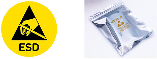
Electrostatic Discharge Protection and Handling

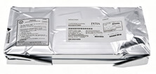
All electrostatic-sensitive components are handled in accordance with electrostatic discharge control procedures. The products are hermetically sealed in anti-static safe packaging to prevent electrostatic damage. Appropriate labeling is also applied for identification and traceability. This ensures product integrity during storage, handling and transportation.


ESD

Certifications & Memberships

Third-party certified, strict quality control. Our certification
  • ISO 9001: 2015
  • ISO 13485: 2016
  • ISO 14001: 2015
  • ISO 28000: 2007
  • ISO 45001: 2018
  • GB/T 27922-2011
  • SMTA
  • IPC
  • ESD
  • PSMA
U413J2ZQE2 Image

U413J2ZQE2

C&K
98D-U413J2ZQE2

Want a better price? Add to Cart and Submit RFQ now, we'll contact you immediately.

0 RFQ
Shopping cart (0 Items)
It is empty.
Compare List (0 Items)
It is empty.
Feedback

Your feedback matters! At Allelco, we value the user experience and strive to improve it constantly.
Please share your comments with us via our feedback form, and we'll respond promptly.
Thank you for choosing Allelco.

Subject
E-mail
Comments
Captcha
Drag or click to upload file
Upload File
types: .xls, .xlsx, .doc, .docx, .jpg, .png and .pdf.
Max file size: 10MB