View All

Please refer to the English Version as our Official Version.Return

Europe
France(Français) Germany(Deutsch) Italy(Italia) Russian(русский) Poland(polski) Czech(Čeština) Luxembourg(Lëtzebuergesch) Netherlands(Nederland) Iceland(íslenska) Hungarian(Magyarország) Spain(español) Portugal(Português) Turkey(Türk dili) Bulgaria(Български език) Ukraine(Україна) Greece(Ελλάδα) Israel(עִבְרִית) Sweden(Svenska) Finland(Svenska) Finland(Suomi) Romania(românesc) Moldova(românesc) Slovakia(Slovenská) Denmark(Dansk) Slovenia(Slovenija) Slovenia(Hrvatska) Croatia(Hrvatska) Serbia(Hrvatska) Montenegro(Hrvatska) Bosnia and Herzegovina(Hrvatska) Lithuania(lietuvių) Spain(Português) Switzerland(Deutsch) United Kingdom(English)
Asia/Pacific
Japan(日本語) Korea(한국의) Thailand(ภาษาไทย) Malaysia(Melayu) Singapore(Melayu) Vietnam(Tiếng Việt) Philippines(Pilipino)
Africa, India and Middle East
United Arab Emirates(العربية) Iran(فارسی) Tajikistan(فارسی) India(हिंदी) Madagascar(malaɡasʲ)
South America / Oceania
New Zealand(Maori) Brazil(Português) Angola(Português) Mozambique(Português)
North America
United States(English) Canada(English) Haiti(Ayiti) Mexico(español)
HomeProductsIntegrated Circuits (ICs)Clock/Timing - Application SpecificPI6C20800SVE
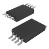
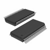
PI6C20800SVE Image
Image may be representation.
See specifications for product details.
EXPRESS OPTION
Payment method

PI6C20800SVE - Diodes Incorporated

Manufacturer Part Number
PI6C20800SVE
Manufacturer
Diodes Incorporated
Allelco Part Number
32D-PI6C20800SVE
Warranty
1 Year Allelco Warranty - Find out more
Stock Status:
11,670 pcs available, New & Original
Parts Description
IC CLOCK BUFFER 1:8 48TSSOP
Package
48-SSOP
Data sheet
PI6C20800SVE.pdf
RoHs Status
ROHS3 Compliant
Our certification
In stock: 11670

Required fields are indicated by an asterisk (*)
Please send RFQ, we will respond immediately.

Quantity

Specifications

PI6C20800SVE Tech Specifications
Diodes Incorporated - PI6C20800SVE technical specifications, attributes, parameters and parts with similar specifications to Diodes Incorporated - PI6C20800SVE

Product Attribute Attribute Value
Manufacturer Diodes Incorporated
Voltage - Supply 3.135V ~ 3.465V
Supplier Device Package 48-SSOP
Series -
Ratio - Input:Output 1:8
Package / Case 48-BSSOP (0.295', 7.50mm Width)
Package Tube
PLL Yes
Output HCSL
Product Attribute Attribute Value
Operating Temperature 0°C ~ 70°C
Number of Circuits 1
Mounting Type Surface Mount
Main Purpose PCI Express (PCIe)
Input HCSL
Frequency - Max 400MHz
Differential - Input:Output Yes/Yes
Base Product Number PI6C20800

Environmental & Export Classifications

ATTRIBUTE DESCRIPTION
RoHs Status ROHS3 Compliant
Moisture Sensitivity Level (MSL) 1 (Unlimited)
REACH Status REACH Unaffected
ECCN EAR99
HTSUS 8542.39.0001

Parts Introduction

PI6C20800SVE Image
PI6C20800SVE (1)

Manufacturer Part Number

PI6C20800SVE

Manufacturer

diodes

Introduction

The PI6C20800SVE is a high-performance, low-power clock distribution buffer designed for PCI Express (PCIe) applications. It features a 1:8 clock signal distribution with HCSL input and output, enabling high-speed signal transmission and low electromagnetic interference (EMI).

Product Features and Performance

1:8 clock signal distribution

HCSL input and output

Supports up to 400MHz frequency

Operates on 3.3V supply voltage

0°C to 70°C operating temperature range

Surface mount package (48-BSSOP)

Product Advantages

Efficient clock signal distribution for PCIe applications

Low power consumption

Reliable high-speed performance

Compact surface mount package

Key Reasons to Choose This Product

Optimized for PCI Express (PCIe) applications

Excellent clock signal distribution and transmission performance

Low power consumption for energy-efficient designs

Compact surface mount package for space-constrained designs

Quality and Safety Features

Robust design for reliable operation

Complies with industry standards and regulations

Compatibility

This product is designed for PCI Express (PCIe) applications and is compatible with the required HCSL input and output standards.

Application Areas

PCI Express (PCIe) systems

High-speed clock distribution in electronic devices

Product Lifecycle

The PI6C20800SVE is an obsolete product, and customers should contact our website's sales team for information on equivalent or alternative models available.

Frequently Asked Questions(FAQ)

What are the key performance specifications of the PI6C20800SVE clock buffer that make it suitable for PCI Express Gen 3 applications?
The PI6C20800SVE operates at a maximum frequency of 400MHz, which aligns with PCIe Gen 3 signaling rates, and maintains signal integrity through differential HCSL input and output configurations. With a 1:8 fan-out capability, it efficiently distributes reference clocks across multiple endpoints while preserving timing accuracy. Its voltage supply range of 3.135V to 3.465V ensures compatibility with standard 3.3V PCIe systems, and the device’s PLL-based architecture provides jitter attenuation essential for reliable link training and data transmission in high-speed serial links.
How does the PI6C20800SVE compare to alternative clock buffers like the PI6C20800 in terms of package and thermal management for compact PCB designs?
While both share the same base model (PI6C20800), the PI6C20800SVE is housed in a 48-pin SSOP package measuring 7.50mm wide, offering higher pin density than larger alternatives such as TQFP or QFN variants. This compact footprint supports space-constrained motherboard layouts common in embedded systems. However, due to the absence of an exposed thermal pad, the SVE package relies solely on conduction through leads, requiring careful attention to copper area and thermal vias during layout to manage junction temperatures within safe limits during continuous operation at full load.
Can the PI6C20800SVE be used in PCIe Gen 4 systems, and what limitations should designers consider?
Although the PI6C20800SVE supports up to 400MHz—adequate for PCIe Gen 3’s 8GT/s line rate—it may not meet Gen 4’s stricter jitter and phase noise requirements without additional filtering or post-amplification. The device lacks adaptive equalization or advanced de-emphasis features found in newer generation buffers. Therefore, while functional in Gen 4 environments under light loads, system architects must validate eye diagram performance and ensure compliance with OIP3 and BER thresholds before deployment in Gen 4 topologies.
What impact does operating temperature have on the reliability of the PI6C20800SVE in industrial versus commercial applications?
The PI6C20800SVE is rated from 0°C to 70°C, aligning with standard commercial-grade operation. In contrast, industrial systems often require -40°C to +85°C operation, where reduced carrier mobility and increased leakage current can degrade PLL stability and skew performance. Designers extending beyond this range must account for longer startup times, potential frequency drift, and accelerated aging effects, particularly when driving multiple loads across temperature gradients.
How many downstream devices can the PI6C20800SVE reliably drive using HCSL outputs before requiring level translation?
The PI6C20800SVE is specified to support one output, but its 1:8 internal ratio implies it can buffer one input to eight identical outputs simultaneously. Each HCSL output typically drives 1–2 receivers directly; however, capacitive loading increases with each added receiver. Exceeding three or four receivers without buffering may result in rise time degradation or signal reflection. For longer traces or fanouts beyond five, external line drivers or reclockers are recommended to maintain signal quality.
Is the PI6C20800SVE suitable for use in systems requiring low jitter performance under dynamic load conditions?
Yes, provided the design adheres to layout best practices. The integrated PLL helps suppress power supply noise and reference jitter, but transient load changes on the output stage can introduce short-term phase noise. At 400MHz, even minor impedance mismatches or simultaneous switching noise can elevate RMS jitter above 500fs, potentially violating PCIe Class 1 requirements. Proper termination, ground plane integrity, and decoupling near the IC significantly mitigate these effects.
What considerations apply when cascading the PI6C20800SVE in multi-stage clock distribution trees?
Cascading introduces cumulative jitter and latency, so each additional stage degrades overall timing margin. The PI6C20800SVE’s single-input architecture limits flexibility compared to multi-input buffers, making it more appropriate for point-to-multipoint topologies rather than hierarchical trees. If tree depth exceeds two levels, consider using lower-jitter sources or active reclocking nodes to prevent BER degradation over long traces or complex routing.
How does the Moisture Sensitivity Level (MSL) of the PI6C20800SVE affect assembly process control?
With an MSL rating of 1, the PI6C20800SVE poses no risk of moisture-induced damage during standard reflow soldering, allowing unlimited storage time before processing without baking. This simplifies procurement and inventory management for commercial electronics manufacturers who do not handle extreme environmental stress testing or high-reliability military applications where stricter handling protocols might still apply.
Can the PI6C20800SVE operate without an external crystal oscillator, and if so, what interface configuration enables this?
No, the PI6C20800SVE requires a stable differential reference input (HCSL or LVDS compatible). It does not include an on-chip oscillator; thus, an external clock source such as a crystal oscillator or disciplined oscillator must provide the reference signal. The device accepts differential signals with typical swing of 400mVpp, so level-shifting or AC-coupling may be necessary depending on the source’s output format.
What precautions should be taken when routing HCSL signals connected to the PI6C20800SVE to minimize EMI and crosstalk?
Maintain controlled impedance (typically 100Ω differential) for all HCSL nets, route them as tightly coupled pairs, and avoid parallel routing with noisy lines such as USB or DDR clocks. Keep traces short and symmetrical to reduce skew, and place bypass capacitors as close as possible to the VCC pins. Additionally, ensure adequate separation between input and output paths to prevent feedback coupling into the PLL, which could destabilize the internal oscillator loop.
Does the PI6C20800SVE support hot-swapping or hot-plug functionality required by some PCIe implementations?
No, the PI6C20800SVE is not designed for hot-plug support. It assumes a powered-down environment during insertion and lacks protection circuits for inrush current or ESD during live insertion. Hot-plugging must be managed at the system level using dedicated controllers and connectors compliant with PCI-SIG specifications, with clock buffering handled only after power sequencing is complete.
How does supply voltage variation within the 3.135V–3.465V window affect the PI6C20800SVE’s jitter and propagation delay?
Within this range, the PI6C20800SVE exhibits minimal sensitivity to supply variations, thanks to its regulated internal circuitry. However, near the lower end (e.g., 3.135V), slight increases in propagation delay and marginal rise/fall times may occur, especially when driving heavy capacitive loads. Designers targeting tight timing budgets should verify worst-case performance at minimum supply using actual test vectors rather than relying solely on nominal values.
Is there a difference in performance between using the PI6C20800SVE in standalone mode versus integrating it into a larger timing subsystem?
In standalone mode, the PI6C20800SVE functions well as a clean-up buffer but cannot compensate for poor-quality references or long trace lengths. When embedded in a larger subsystem with disciplined clocks, global timing budget improves, but added complexity may offset gains unless the reference itself is high-quality. Thus, the optimal configuration depends on upstream clock purity and downstream distribution needs.
What role does the PLL play in the PI6C20800SVE’s ability to reject input jitter, and how does lock time impact system initialization?
The PLL acts as a narrowband filter that attenuates broadband jitter from the reference source while tracking the fundamental frequency. Lock time typically ranges from tens to hundreds of microseconds, depending on initial frequency offset and loop bandwidth settings. During system boot, this delay contributes to overall initialization time, so applications requiring rapid synchronization may benefit from pre-aligned references or faster-locking PLL configurations if supported by firmware.
Are there any known limitations regarding simultaneous switching noise (SSN) when using the PI6C20800SVE with FPGAs or ASICs?
Yes. High di/dt currents from adjacent FPGA banks can induce voltage fluctuations in shared power rails, potentially causing the PI6C20800SVE’s PLL to lose lock momentarily. To mitigate, use local decoupling (10µF bulk + 0.1µF ceramic per VCC pin), isolate analog and digital grounds at the IC, and avoid placing noisy components directly adjacent to clock inputs/outputs on the PCB.
How does the absence of enable/disable pin functionality in the PI6C20800SVE affect power sequencing in multi-voltage systems?
Without a dedicated shutdown pin, powering down the PI6C20800SVE requires removing VCC entirely, which complicates partial power gating strategies. This forces full system resets during sleep modes and increases power-on reset complexity. Designers seeking fine-grained control may need external logic to condition the reference input or switch to a secondary clock source during low-power states.
What documentation or reference designs accompany the PI6C20800SVE to aid in layout and application development?
Diodes Incorporated provides a datasheet with electrical characteristics, recommended PCB layout guidelines, and typical application diagrams showing proper termination and decoupling. However, unlike some competitors, it does not always include full reference schematics or IBIS models. Engineers are advised to consult third-party evaluation boards or collaborate with distributors for supplemental simulation files when optimizing high-speed signal paths.
Given its RoHS3 compliance and EAR99 classification, what export or regulatory constraints apply to the PI6C20800SVE?
As an EAR99 item, the PI6C20800SVE is subject to general U.S. export controls but generally does not require special licenses for most commercial end uses. RoHS3 compliance ensures halogen-free and restricted substance content, facilitating global market access. Still, final determination depends on destination country regulations and intended application, particularly in defense or telecommunications sectors where additional screening may apply.

Parts with Similar Specifications

The three parts on the right have similar specifications to Diodes Incorporated PI6C20800SVE

Product Attribute PI6C20800SIVE PI6C20800SIVEX PI6C20800SVEX PI6C20800VEX
Part Number PI6C20800SIVE PI6C20800SIVEX PI6C20800SVEX PI6C20800VEX
Manufacturer Diodes Incorporated Diodes Incorporated Diodes Incorporated Diodes Incorporated
Ratio - Input:Output - - - -
Package - Tape & Reel (TR) Tube Tape & Reel (TR)
Output - - - -
Supplier Device Package - 196-NFBGA (12x12) 16-PDIP 64-VQFN (9x9)
Main Purpose - - - -
Voltage - Supply - - - -
Number of Circuits - - - -
Operating Temperature - -40°C ~ 85°C 0°C ~ 70°C -40°C ~ 85°C
Differential - Input:Output - - - -
Series - - - -
Input - - - -
Base Product Number - DAC34H84 MAX500 ADS62P42
PLL - - - -
Frequency - Max - - - -
Package / Case - 196-LFBGA 16-DIP (0.300', 7.62mm) 64-VFQFN Exposed Pad
Mounting Type - Surface Mount Through Hole Surface Mount

PI6C20800SVE Datasheet PDF

Download PI6C20800SVE pdf datasheets and Diodes Incorporated documentation for PI6C20800SVE - Diodes Incorporated.

Datasheets
PI6C20800S.pdf
Environmental Information
Cylindrical Battery Holders.pdf
PCN Packaging
Labeling Change 30/Sep/2016.pdf Labeling Change Revision 12/Apr/2017.pdf
PCN Obsolescence/ EOL
Cylindrical Battery Holders.pdf
PCN Assembly/Origin
PI6C2YYY 20/Apr/2018.pdf

Customer Reviews

Evaluation: 10 Articles

  • ECUb***h
    Sep 22, 2026

    Used for repair of an older automotive ECU. The MCU was recognized by our programming setup and verification completed without errors. The repaired board now starts and communicates normally.

  • RS48***ieldTech
    Sep 16, 2026

    Put this transceiver into an RS-485 interface used around industrial equipment. Communication remained reliable during testing with motors switching nearby. Good result for the replacement board.

  • Logi***b_Chris
    Sep 8, 2026

    Purchased for a Cyclone III development project. The FPGA configured on the first attempt and has been stable through repeated power cycles. No problems with the I/O we are using.

  • Circ***FixerTom
    Sep 2, 2026

    Used this rectifier in a high-current power supply repair. Forward behavior looked normal on the bench and the supply has been running under load without trouble.

  • Retr***UWorks
    Aug 31, 2026

    Needed the exact ST10F269Z2Q6 for servicing an older control unit. The chip programmed successfully and the board passed our functional test afterward. Much easier than redesigning around a newer MCU.

  • Andr***PCBLab
    Aug 28, 2026

    I needed this ADC for an older data acquisition board. Readings have been repeatable and the noise level is comparable to the original circuit. Happy with the purchase.

  • Leat***O'Keefe
    Aug 20, 2026

    one of my hobbies is skydiving. and when i'm skydiving this works great.

  • Ilen***
    Aug 20, 2026

    This product works considerably well. It secretly improves my basketball by a lot.

  • Indu***ialPower
    Aug 17, 2026

    Installed this IGBT module in a power conversion cabinet. Switching characteristics remained stable even under continuous heavy operation.

  • Nikh***ech
    Aug 13, 2026

    Great low-power MCU for portable equipment. Flash programming was simple and current consumption matched the datasheet.

Write a Review

Your Email address will not be published.

Shipment

Delivery Time

In-stock items can be shipped within 24 hours. Some parts will be arranged for delivery within 1-2 days from the date all items arrive at our warehouse. And Allelco ships order once a day at about 17:00, except Sunday. Once the goods are shipped, the estimated delivery time depends on the shipping methods and Delivery destination. The table below shows are the logistic time for some common countries.

Delivery Cost

  1. Use your express account for shipment if you have one.
  2. Use our account for the shipment. Refer to the table below for the approximate charges.
(Different time frame / countries / package size has different price.)

Delivery Method

  1. Global Common Shipment by DHL / UPS / FedEx / TNT / EMS / SF we support.
  2. Others more shipping ways, please get in touch with your customer manager.

Common Countries Logistic Time Reference
Region Country Logistic Time(Day)
America United States 5
Brazil 7
Europe Germany 5
United Kingdom 4
Italy 5
Oceania Australia 6
New Zealand 5
Asia India 4
Japan 4
Middle East Israel 6
DHL & FedEx Shipment Charges Reference
Shipment charges(KG) Reference DHL(USD$)
0.00kg-1.00kg USD$30.00 - USD$60.00
1.00kg-2.00kg USD$40.00 - USD$80.00
2.00kg-3.00kg USD$50.00 - USD$100.00
Note:
The above table is for reference only. There may have some data bias for the uncontrollable factors.
Contact us if you have any questions.
  • QC (Quality Warranty)
  • Payment Support
  • Packaging
  • Certifications & Memberships

QC (Quality Warranty)

Allelco is committed to exceeding customer expectations through customer service excellence, order accuracy, and on-time delivery.
This is achieved through our commitment to the continual improvement of our processes, services, and products.


Strict quality inspection builds a solid foundation for electronic component quality.
  1. Visual inspection
  2. Performance testing and reliability verification
  3. Standardized full-process testing
  4. Precise control of every parameter
We eliminate defective components and ensure the stable operation of electronic devices through professional quality standards.

Payment Support

The payment method can be chosen from the methods shown below: Wire Transfer (T/T, Bank Transfer), Western Union, Credit card, PayPal.
  • HKBea
  • Paypal
  • MasterCard
  • Western-Union
  • VISA
Stable Delivery, Sincere Partnership — Your Faithful Supply Chain Partner
  • Efficient Supply Management
  • Cost-Saving Procurement
  • Fast Sourcing & Delivery
Contact us if you have any questions.

Packaging

Electrostatic Discharge Protection and Handling

All electrostatic-sensitive components are handled in accordance with electrostatic discharge control procedures. The products are hermetically sealed in anti-static safe packaging to prevent electrostatic damage. Appropriate labeling is also applied for identification and traceability. This ensures product integrity during storage, handling and transportation.


ESD

Certifications & Memberships

Third-party certified, strict quality control. Our certification
  • ISO 9001: 2015
  • ISO 13485: 2016
  • ISO 14001: 2015
  • ISO 28000: 2007
  • ISO 45001: 2018
  • GB/T 27922-2011
  • SMTA
  • IPC
  • ESD
  • PSMA
PI6C20800SVE Image

PI6C20800SVE

Diodes Incorporated
32D-PI6C20800SVE

Want a better price? Add to Cart and Submit RFQ now, we'll contact you immediately.

0 RFQ
Shopping cart (0 Items)
It is empty.
Compare List (0 Items)
It is empty.
Feedback

Your feedback matters! At Allelco, we value the user experience and strive to improve it constantly.
Please share your comments with us via our feedback form, and we'll respond promptly.
Thank you for choosing Allelco.

Subject
E-mail
Comments
Captcha
Drag or click to upload file
Upload File
types: .xls, .xlsx, .doc, .docx, .jpg, .png and .pdf.
Max file size: 10MB