View All

Please refer to the English Version as our Official Version.Return

Europe
France(Français) Germany(Deutsch) Italy(Italia) Russian(русский) Poland(polski) Czech(Čeština) Luxembourg(Lëtzebuergesch) Netherlands(Nederland) Iceland(íslenska) Hungarian(Magyarország) Spain(español) Portugal(Português) Turkey(Türk dili) Bulgaria(Български език) Ukraine(Україна) Greece(Ελλάδα) Israel(עִבְרִית) Sweden(Svenska) Finland(Svenska) Finland(Suomi) Romania(românesc) Moldova(românesc) Slovakia(Slovenská) Denmark(Dansk) Slovenia(Slovenija) Slovenia(Hrvatska) Croatia(Hrvatska) Serbia(Hrvatska) Montenegro(Hrvatska) Bosnia and Herzegovina(Hrvatska) Lithuania(lietuvių) Spain(Português) Switzerland(Deutsch) United Kingdom(English)
Asia/Pacific
Japan(日本語) Korea(한국의) Thailand(ภาษาไทย) Malaysia(Melayu) Singapore(Melayu) Vietnam(Tiếng Việt) Philippines(Pilipino)
Africa, India and Middle East
United Arab Emirates(العربية) Iran(فارسی) Tajikistan(فارسی) India(हिंदी) Madagascar(malaɡasʲ)
South America / Oceania
New Zealand(Maori) Brazil(Português) Angola(Português) Mozambique(Português)
North America
United States(English) Canada(English) Haiti(Ayiti) Mexico(español)
HomeProductsIntegrated Circuits (ICs)Logic - Shift Registers74HCT595D/S400118
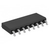
74HCT595D/S400118 Image
Image may be representation.
See specifications for product details.
EXPRESS OPTION
Payment method

74HCT595D/S400118 - NXP USA Inc.

Manufacturer Part Number
74HCT595D/S400118
Manufacturer
NXP Semiconductors
Allelco Part Number
98D-74HCT595D/S400118
Warranty
1 Year Allelco Warranty - Find out more
Stock Status:
15,561 pcs available, New & Original
Parts Description
SERIAL IN PARALLEL OUT
Package
16-SO
Data sheet
74HCT595D/S4001.pdf

Datasheets

74HC(T)595.pdf
RoHs Status
 
Our certification
In stock: 15561
  • Unit Price: $0.224
  • Subtotal: $0.00

Want a better price?
Add to Cart and Submit RFQ now, we'll contact you immediately.

Quantity Unit Price Ext. Price
1+ $0.224 $0.22
200+ $0.087 $17.40
500+ $0.083 $41.50
1000+ $0.082 $82.00
The above prices does not include taxes and freight rates, which will be calculated on the order pages.


Specifications

74HCT595D/S400118 Tech Specifications
NXP USA Inc. - 74HCT595D/S400118 technical specifications, attributes, parameters and parts with similar specifications to NXP USA Inc. - 74HCT595D/S400118

Product Attribute Attribute Value
Manufacturer NXP Semiconductors
Voltage - Supply 4.5V ~ 5.5V
Supplier Device Package 16-SO
Series 74HCT
Package / Case 16-SOIC (0.154", 3.90mm Width)
Package Bulk
Output Type Tri-State
Product Attribute Attribute Value
Operating Temperature -40°C ~ 125°C
Number of Elements 1
Number of Bits per Element 8
Mounting Type Surface Mount
Logic Type Shift Register
Function Serial to Parallel, Serial
Base Product Number 74HCT595

Environmental & Export Classifications

ATTRIBUTE DESCRIPTION
RoHs Status Not applicable
Moisture Sensitivity Level (MSL) 3 (168 Hours)
REACH Status Vendor Undefined
ECCN EAR99
HTSUS 8542.39.0001

Frequently Asked Questions(FAQ)

How does the 74HCT595D/S400118 handle voltage levels when interfacing with mixed logic families in a 5V system, and what are the implications for noise margin?
The 74HCT595D/S400118 operates from a supply range of 4.5V to 5.5V and is designed to be compatible with TTL voltage thresholds, making it suitable for mixed logic environments. Its input high threshold is typically around 2.0V at 4.5V supply, aligning closely with standard TTL inputs. This ensures reliable recognition of logic highs from 3.5V or higher, which reduces the risk of misinterpretation in systems where CMOS devices may output lower voltages. However, care must be taken when driving its outputs into other CMOS stages, as the output high voltage (VOH) can drop below 4.2V at maximum load current, potentially causing marginal noise margins if not properly matched.
What are the timing constraints for shifting data into the 74HCT595D/S400118 when using a microcontroller running at 3.3V with a clock frequency of 10 MHz?
At 5V operation, the 74HCT595D/S400118 supports a maximum clock frequency of approximately 32 MHz for reliable data capture on the rising edge of SH_CP. With a 10 MHz clock from a 3.3V microcontroller, timing is well within spec, provided the signal integrity and rise/fall times meet requirements. However, since the HCT family has slower propagation delays compared to HC or standard CMOS, the total shift register latency—approximately 8 × tpd (~100 ns at 5V)—must be factored into timing budgets for downstream control signals like ST_CP activation.
Can the 74HCT595D/S400118 drive inductive loads such as relays directly, and what additional components are recommended for robust switching?
The 74HCT595D/S400118 can source or sink up to 6 mA per output pin, which is insufficient for most relay coils without external buffering. Direct drive risks exceeding current limits and damaging the IC. A common solution is to use an NPN transistor (e.g., 2N3904) or MOSFET (e.g., IRLZ44N) as a switch, driven by the output. A flyback diode across the relay coil—such as 1N4148 or better yet, a Schottky like 1N5819—is essential to suppress inductive kickback. This approach protects both the 74HCT595D/S400118 and improves system reliability in industrial applications.
How does temperature variation affect the propagation delay and power consumption of the 74HCT595D/S400118 across its operating range from -40°C to +125°C?
Over the full temperature range, the propagation delay of the 74HCT595D/S400118 increases significantly at elevated temperatures due to reduced carrier mobility in silicon. At +125°C, typical delays can extend to 30–40 ns per stage, versus ~10 ns at room temperature. Power consumption also rises slightly with temperature because of increased leakage currents, though this effect is modest in HCT logic. Designers should ensure that setup and hold times remain satisfied under worst-case thermal conditions, especially in high-speed serial-in/parallel-out sequences involving multiple cascaded registers.
What is the difference between using the 74HCT595D/S400118 in serial-to-serial versus parallel output mode, and how does each affect system throughput?
In serial-to-serial mode, all eight bits are shifted through a single data line with each clock pulse, requiring eight clock cycles to transfer one byte. In contrast, parallel output mode uses all eight pins simultaneously to latch data after a strobe pulse (ST_CP), enabling full-byte transfer in one cycle once loaded. For applications like LED matrix scanning, parallel mode maximizes data throughput but consumes more pins; serial mode saves GPIOs but trades off speed. The 74HCT595D/S400118 supports both via internal architecture, allowing flexible trade-offs between pin count and update rate depending on application needs.
Is it safe to cascade multiple 74HCT595D/S400118 ICs for wider data buses, and what precautions are necessary to maintain signal integrity?
Cascading multiple 74HCT595D/S400118 devices is feasible and commonly done for wider parallel outputs. However, cumulative propagation delays across stages must be accounted for, particularly when using the serial output (Q7S) to feed into the next chip’s SER input. Additionally, loading effects on clock and latch lines increase with each stage, potentially degrading rise/fall times. To mitigate this, buffered clock drivers or series resistors on long traces may be required. Ensuring that the total capacitive load on control lines remains below 50 pF helps preserve signal fidelity across cascaded chains.
How does the tri-state output feature of the 74HCT595D/S400118 improve bus sharing in multi-device environments, and what triggers the high-impedance state?
The 74HCT595D/S400118 includes OE (output enable) functionality that allows active-low assertion of the outputs into a high-impedance state. This enables safe bus sharing among multiple peripherals without contention, such as when several shift registers share a common output line routed to displays or sensors. The high-Z state is activated only when OE is pulled low, independent of clock or latch states. Designers must ensure that OE is controlled synchronously with data updates to prevent glitches during transitions, especially when switching between master and slave modes in daisy-chained configurations.
What are the key differences between the 74HCT595D/S400118 and the 74HC595N in terms of packaging, performance, and real-world suitability for high-reliability applications?
While both devices share identical electrical characteristics, the 74HCT595D/S400118 comes in an SO-16 package and is optimized for 5V operation with TTL-compatible inputs, whereas the 74HC595N uses DIP-16 and targets 3.3V logic systems. The 74HCT595D/S400118’s wider supply tolerance (4.5–5.5V vs. 2–6V nominal for HC) makes it more robust in legacy 5V environments with voltage drops. Additionally, the tape-and-reel packaging of the 74HCT595D/S400118 aligns with automated assembly processes, improving yield in mass production. For high-reliability systems, the tighter voltage window reduces risk of undefined states during brownout conditions.
What precautions should be taken during PCB layout when routing signals to and from the 74HCT595D/S400118 to minimize electromagnetic interference and crosstalk?
Given the 74HCT595D/S400118’s fast switching edges and parallel output capability, careful trace routing is essential. Clock lines (SH_CP, ST_CP) should be kept short and away from analog or sensitive signal paths to reduce radiated noise. Outputs should be terminated with series resistors (e.g., 22–100 Ω) near the IC to dampen reflections, especially in unterminated long runs. Grounding the exposed pad effectively via multiple vias enhances heat dissipation and stabilizes reference potential, reducing ground bounce. Avoiding parallel routing of high-speed lines adjacent to power rails further minimizes capacitive coupling and EMI susceptibility.
How does the 74HCT595D/S400118 perform in automotive-grade environments, and does it meet functional safety considerations for ECU applications?
Although not explicitly qualified to AEC-Q100 standards, the 74HCT595D/S400118 is specified over a commercial temperature range (-40°C to +125°C), which overlaps with some automotive sub-bands. Its robust ESD protection (typically >2 kV HBM) and stable operation under voltage transients make it suitable for non-critical I/O expansion in infotainment or body electronics. However, for ASIL-rated systems, formal qualification to automotive standards would be required. Designers should supplement with transient voltage suppressors and conformal coating if deployed in harsh environments to enhance long-term reliability beyond datasheet guarantees.
What is the impact of enabling the output disable function (via OE pin) on power consumption and response time in battery-powered designs?
When OE is asserted low, the 74HCT595D/S400118 enters a low-power standby mode where output drivers are turned off, reducing static current draw by nearly an order of magnitude—from ~1 μA to <0.1 μA per device. This is beneficial in sleep-mode applications like remote sensor nodes. However, transitioning from high-Z back to active requires time for internal biasing circuits to stabilize, adding ~100 ns to output response latency. Thus, while power savings are significant, real-time responsiveness must be evaluated against duty cycle requirements in energy-constrained systems.
How do you verify correct operation of the 74HCT595D/S400118 during firmware development, and what test patterns are recommended for validating data integrity?
Functional verification begins with applying alternating bit patterns (e.g., 0xAA, 0x55) during shift operations to detect skew or corruption. A walking 1s pattern (0x01, 0x02, 0x04, ..., 0x80) stresses individual output channels and confirms proper isolation and latching. Monitoring Q7S during continuous shifting validates serial chain continuity. Firmware should include checks for OE deassertion timing relative to ST_CP to avoid race conditions. Oscilloscope probing of clock and data lines helps confirm clean transitions, while logic analyzers capture full protocol compliance across reset-to-run sequences.

Parts with Similar Specifications

The three parts on the right have similar specifications to NXP USA Inc. 74HCT595D/S400118

Product Attribute 74HCT595D-Q100,118 74HCT595BQ-Q100,11 74HCT595D,118 74HCT595DB,118
Part Number 74HCT595D-Q100,118 74HCT595BQ-Q100,11 74HCT595D,118 74HCT595DB,118
Manufacturer Nexperia USA Inc. Nexperia USA Inc. NXP USA Inc. Nexperia USA Inc.
Base Product Number - DAC34H84 MAX500 ADS62P42
Series - - - -
Number of Elements - - - -
Package - Tape & Reel (TR) Tube Tape & Reel (TR)
Function - - - -
Output Type - Current - Unbuffered Voltage - Buffered -
Number of Bits per Element - - - -
Voltage - Supply - - - -
Logic Type - - - -
Operating Temperature - -40°C ~ 85°C 0°C ~ 70°C -40°C ~ 85°C
Mounting Type - Surface Mount Through Hole Surface Mount
Package / Case - 196-LFBGA 16-DIP (0.300', 7.62mm) 64-VFQFN Exposed Pad
Supplier Device Package - 196-NFBGA (12x12) 16-PDIP 64-VQFN (9x9)

74HCT595D/S400118 Datasheet PDF

Download 74HCT595D/S400118 pdf datasheets and NXP USA Inc. documentation for 74HCT595D/S400118 - NXP USA Inc..

Datasheets
74HC(T)595.pdf

Customer Reviews

Evaluation: 10 Articles

  • ECUb***h
    Sep 22, 2026

    Used for repair of an older automotive ECU. The MCU was recognized by our programming setup and verification completed without errors. The repaired board now starts and communicates normally.

  • RS48***ieldTech
    Sep 16, 2026

    Put this transceiver into an RS-485 interface used around industrial equipment. Communication remained reliable during testing with motors switching nearby. Good result for the replacement board.

  • Logi***b_Chris
    Sep 8, 2026

    Purchased for a Cyclone III development project. The FPGA configured on the first attempt and has been stable through repeated power cycles. No problems with the I/O we are using.

  • Circ***FixerTom
    Sep 2, 2026

    Used this rectifier in a high-current power supply repair. Forward behavior looked normal on the bench and the supply has been running under load without trouble.

  • Retr***UWorks
    Aug 31, 2026

    Needed the exact ST10F269Z2Q6 for servicing an older control unit. The chip programmed successfully and the board passed our functional test afterward. Much easier than redesigning around a newer MCU.

  • Andr***PCBLab
    Aug 28, 2026

    I needed this ADC for an older data acquisition board. Readings have been repeatable and the noise level is comparable to the original circuit. Happy with the purchase.

  • Leat***O'Keefe
    Aug 20, 2026

    one of my hobbies is skydiving. and when i'm skydiving this works great.

  • Ilen***
    Aug 20, 2026

    This product works considerably well. It secretly improves my basketball by a lot.

  • Indu***ialPower
    Aug 17, 2026

    Installed this IGBT module in a power conversion cabinet. Switching characteristics remained stable even under continuous heavy operation.

  • Nikh***ech
    Aug 13, 2026

    Great low-power MCU for portable equipment. Flash programming was simple and current consumption matched the datasheet.

Write a Review

Your Email address will not be published.

Shipment

Delivery Time

In-stock items can be shipped within 24 hours. Some parts will be arranged for delivery within 1-2 days from the date all items arrive at our warehouse. And Allelco ships order once a day at about 17:00, except Sunday. Once the goods are shipped, the estimated delivery time depends on the shipping methods and Delivery destination. The table below shows are the logistic time for some common countries.

Delivery Cost

  1. Use your express account for shipment if you have one.
  2. Use our account for the shipment. Refer to the table below for the approximate charges.
(Different time frame / countries / package size has different price.)

Delivery Method

  1. Global Common Shipment by DHL / UPS / FedEx / TNT / EMS / SF we support.
  2. Others more shipping ways, please get in touch with your customer manager.

Common Countries Logistic Time Reference
Region Country Logistic Time(Day)
America United States 5
Brazil 7
Europe Germany 5
United Kingdom 4
Italy 5
Oceania Australia 6
New Zealand 5
Asia India 4
Japan 4
Middle East Israel 6
DHL & FedEx Shipment Charges Reference
Shipment charges(KG) Reference DHL(USD$)
0.00kg-1.00kg USD$30.00 - USD$60.00
1.00kg-2.00kg USD$40.00 - USD$80.00
2.00kg-3.00kg USD$50.00 - USD$100.00
Note:
The above table is for reference only. There may have some data bias for the uncontrollable factors.
Contact us if you have any questions.
  • QC (Quality Warranty)
  • Payment Support
  • Packaging
  • Certifications & Memberships

QC (Quality Warranty)

Allelco is committed to exceeding customer expectations through customer service excellence, order accuracy, and on-time delivery.
This is achieved through our commitment to the continual improvement of our processes, services, and products.


Strict quality inspection builds a solid foundation for electronic component quality.
  1. Visual inspection
  2. Performance testing and reliability verification
  3. Standardized full-process testing
  4. Precise control of every parameter
We eliminate defective components and ensure the stable operation of electronic devices through professional quality standards.

Payment Support

The payment method can be chosen from the methods shown below: Wire Transfer (T/T, Bank Transfer), Western Union, Credit card, PayPal.
  • HKBea
  • Paypal
  • MasterCard
  • Western-Union
  • VISA
Stable Delivery, Sincere Partnership — Your Faithful Supply Chain Partner
  • Efficient Supply Management
  • Cost-Saving Procurement
  • Fast Sourcing & Delivery
Contact us if you have any questions.

Packaging

Electrostatic Discharge Protection and Handling

All electrostatic-sensitive components are handled in accordance with electrostatic discharge control procedures. The products are hermetically sealed in anti-static safe packaging to prevent electrostatic damage. Appropriate labeling is also applied for identification and traceability. This ensures product integrity during storage, handling and transportation.


ESD

Certifications & Memberships

Third-party certified, strict quality control. Our certification
  • ISO 9001: 2015
  • ISO 13485: 2016
  • ISO 14001: 2015
  • ISO 28000: 2007
  • ISO 45001: 2018
  • GB/T 27922-2011
  • SMTA
  • IPC
  • ESD
  • PSMA
74HCT595D/S400118 Image

74HCT595D/S400118

NXP USA Inc.
98D-74HCT595D/S400118

Want a better price? Add to Cart and Submit RFQ now, we'll contact you immediately.

0 RFQ
Shopping cart (0 Items)
It is empty.
Compare List (0 Items)
It is empty.
Feedback

Your feedback matters! At Allelco, we value the user experience and strive to improve it constantly.
Please share your comments with us via our feedback form, and we'll respond promptly.
Thank you for choosing Allelco.

Subject
E-mail
Comments
Captcha
Drag or click to upload file
Upload File
types: .xls, .xlsx, .doc, .docx, .jpg, .png and .pdf.
Max file size: 10MB