View All

Please refer to the English Version as our Official Version.Return

Europe
France(Français) Germany(Deutsch) Italy(Italia) Russian(русский) Poland(polski) Czech(Čeština) Luxembourg(Lëtzebuergesch) Netherlands(Nederland) Iceland(íslenska) Hungarian(Magyarország) Spain(español) Portugal(Português) Turkey(Türk dili) Bulgaria(Български език) Ukraine(Україна) Greece(Ελλάδα) Israel(עִבְרִית) Sweden(Svenska) Finland(Svenska) Finland(Suomi) Romania(românesc) Moldova(românesc) Slovakia(Slovenská) Denmark(Dansk) Slovenia(Slovenija) Slovenia(Hrvatska) Croatia(Hrvatska) Serbia(Hrvatska) Montenegro(Hrvatska) Bosnia and Herzegovina(Hrvatska) Lithuania(lietuvių) Spain(Português) Switzerland(Deutsch) United Kingdom(English)
Asia/Pacific
Japan(日本語) Korea(한국의) Thailand(ภาษาไทย) Malaysia(Melayu) Singapore(Melayu) Vietnam(Tiếng Việt) Philippines(Pilipino)
Africa, India and Middle East
United Arab Emirates(العربية) Iran(فارسی) Tajikistan(فارسی) India(हिंदी) Madagascar(malaɡasʲ)
South America / Oceania
New Zealand(Maori) Brazil(Português) Angola(Português) Mozambique(Português)
North America
United States(English) Canada(English) Haiti(Ayiti) Mexico(español)
HomeProductsRF/IF and RFIDRF Shields53-CBSA-0.5X5.5X0.5
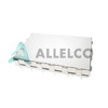
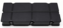
53-CBSA-0.5X5.5X0.5 Image
Image may be representation.
See specifications for product details.
EXPRESS OPTION
Payment method

53-CBSA-0.5X5.5X0.5 - Leader Tech Inc.

Manufacturer Part Number
53-CBSA-0.5X5.5X0.5
Manufacturer
Leader Tech Inc.
Allelco Part Number
98D-53-CBSA-0.5X5.5X0.5
Warranty
1 Year Allelco Warranty - Find out more
Stock Status:
48,630 pcs available, New & Original
Parts Description
RF SHIELD 0.5" X 5.5" T/H
Package
Bulk
Data sheet
53-CBSA-0.5X5.5.pdf
RoHs Status
ROHS3 Compliant
Our certification
In stock: 48630
  • Unit Price: $22.25
  • Subtotal: $0.00

Want a better price?
Add to Cart and Submit RFQ now, we'll contact you immediately.

Quantity Unit Price Ext. Price
1+ $22.25 $22.25
The above prices does not include taxes and freight rates, which will be calculated on the order pages.


Specifications

53-CBSA-0.5X5.5X0.5 Tech Specifications
Leader Tech Inc. - 53-CBSA-0.5X5.5X0.5 technical specifications, attributes, parameters and parts with similar specifications to Leader Tech Inc. - 53-CBSA-0.5X5.5X0.5

Product Attribute Attribute Value
Manufacturer Leader Tech Inc.
Width - Overall 0.500" (12.70mm)
Ventilation Non-Vented
Type Shield, 2-Piece
Series 50-CBS
Product Attribute Attribute Value
Package Bulk
Mounting Type Through Hole
Length - Overall 5.500" (139.70mm)
Height - Overall 0.500" (12.70mm)

Environmental & Export Classifications

ATTRIBUTE DESCRIPTION
RoHs Status ROHS3 Compliant
Moisture Sensitivity Level (MSL) 1 (Unlimited)
REACH Status REACH Unaffected
ECCN EAR99
HTSUS 8529.90.9800

Frequently Asked Questions(FAQ)

How does the 53-CBSA-0.5X5.5X0.5 RF shield compare to vented alternatives in high-humidity environments, and what are the implications for long-term reliability in industrial control systems?
The 53-CBSA-0.5X5.5X0.5 features a non-vented design, which eliminates potential moisture ingress pathways that can occur with vented shields under condensation or washdown conditions. In high-humidity industrial environments, this characteristic reduces the risk of corrosion at mounting points and minimizes internal contamination from ambient moisture. While vented shields may offer better thermal dissipation, the sealed profile of the 53-CBSA variant enhances environmental sealing when integrated with conformal coatings or gaskets, making it preferable for mission-critical applications where reliability outweighs thermal considerations.
What is the recommended PCB layout strategy when integrating the 53-CBSA-0.5X5.5X0.5 RF shield over sensitive analog traces, and how does its 12.7 mm height affect clearance in compact designs?
When mounting the 53-CBSA-0.5X5.5X0.5 over high-impedance analog traces, ensure the shield’s ground connection uses multiple vias spaced no more than λ/10 at the highest operating frequency to maintain effective shielding without inducing ground loops. The 12.7 mm height requires careful Z-axis planning in stacked-layer PCBs; it occupies significant vertical space and must be accounted for in enclosure design. In multi-board systems, this height may necessitate standoff spacers or recessed mounting to avoid interference with adjacent connectors or components.
Can the 53-CBSA-0.5X5.5X0.5 be used for EMI suppression in Class B digital circuits operating at 500 MHz, and how does its material composition influence effectiveness compared to conductive elastomers?
The 53-CBSA-0.5X5.5X0.5 provides moderate EMI suppression suitable for Class B applications up to approximately 500 MHz, primarily through physical isolation and partial reflection of radiated fields. Its effectiveness depends on proper grounding and continuity across seams. Compared to conductive elastomers, which offer tunable contact resistance and flexibility, this rigid metal shield excels in static, high-stability environments but lacks adaptability to surface variations. For frequencies above 500 MHz, additional filtering or layered shielding may be required regardless of enclosure type.
What soldering and rework precautions should be taken when installing the 53-CBSA-0.5X5.5X0.5 in mass production, given its through-hole configuration and 2-piece assembly?
Due to its 2-piece construction and through-hole mounting, the 53-CBSA-0.5X5.5X0.5 demands precise alignment during wave soldering to prevent misregistration between top and bottom shield halves. Hand rework should use low-temperature solder (≤230°C) and minimal dwell time to avoid warping the thin metal structure. Automated optical inspection (AOI) post-assembly helps verify full engagement of both pieces. Excessive heat can compromise dimensional stability, especially near the mounting tabs, leading to poor RF seal integrity.
How does the 53-CBSA-0.5X5.5X0.5 perform in terms of thermal management when installed over power regulators generating 3W of heat, and what mitigation strategies are recommended?
As a non-ventilated, solid-metal enclosure, the 53-CBSA-0.5X5.5X0.5 offers limited passive cooling due to restricted airflow and lack of ventilation. When covering components dissipating 3W, thermal conductivity through the shield is minimal unless bonded to a heatsink. Designers should avoid enclosing such components entirely within the shield cavity; instead, position them at shield edges or integrate external finned heatsinks. Thermal interface materials may improve conduction but do not compensate for inadequate convection.
Is the 53-CBSA-0.5X5.5X0.5 compatible with automated component placement machines, and what packaging considerations affect handling in high-volume manufacturing?
The 53-CBSA-0.5X5.5X0.5 is supplied in bulk packaging, which supports automated pick-and-place systems provided the shield’s flat profile and tab geometry allow stable orientation. However, the fragile nature of thin metal enclosures requires vacuum nozzles with soft tips to prevent deformation. Feeder compatibility depends on tab spacing and rigidity—narrow tabs may bend during feeding. Manufacturers should validate tray designs to minimize lateral forces during placement.
What environmental testing standards apply to the 53-CBSA-0.5X5.5X0.5 for automotive or military-grade deployments, and how does its RoHS3 compliance support regulatory adherence?
For automotive applications, the 53-CBSA-0.5X5.5X0.5 meets basic mechanical durability requirements but must undergo additional validation per AEC-Q200 for passive components. Military specifications (e.g., MIL-PRF-19500) require extended thermal cycling and humidity exposure beyond standard tests. RoHS3 compliance ensures halogen-free materials and restricted substance thresholds, simplifying compliance documentation for EU and global markets. However, functional performance under extreme shock or vibration may still require mechanical reinforcement depending on application severity.
How does the 139.7 mm length of the 53-CBSA-0.5X5.5X0.5 impact shielding effectiveness along its longitudinal axis, and what design adjustments optimize field attenuation?
At higher frequencies (>1 GHz), the 139.7 mm length of the 53-CBSA-0.5X5.5X0.5 introduces potential slotline resonances that reduce shielding effectiveness if not properly terminated. To mitigate this, ensure continuous grounding along the entire length with vias every λ/20 at the target frequency. Splitting the shield into shorter segments with overlapping joints can improve impedance matching and reduce standing waves. Proper bonding at seam interfaces is critical—poor contact increases leakage currents and degrades performance.
What trade-offs exist between using the 53-CBSA-0.5X5.5X0.5 versus custom-machined enclosures in prototype development, particularly regarding cost, lead time, and RF performance?
The 53-CBSA-0.5X5.5X0.5 offers rapid deployment with standard lead times and lower unit costs in small volumes, ideal for early-stage prototyping. However, custom machined enclosures provide superior fit, optimized grounding paths, and tailored venting for thermal control. For final production, the standardized 53-CBSA variant reduces qualification effort and supports supply chain consistency. In high-performance RF prototypes requiring fine-tuned impedance characteristics, custom solutions may outperform off-the-shelf options despite higher NRE and longer delivery times.
Can the 53-CBSA-0.5X5.5X0.5 be used as a Faraday cage for transient voltage suppression devices like TVS diodes, and what grounding topology minimizes surge coupling?
Yes, the 53-CBSA-0.5X5.5X0.5 can serve as a local Faraday cage around ESD-sensitive areas including TVS diodes, provided the enclosure is bonded to the system ground plane with low-inductance connections. Use multiple short ground straps or direct via attachments to minimize loop inductance during fast transients. Avoid single-point grounding if surge energy exceeds 10 A peak—distributed grounding reduces impedance and improves current dispersion. Ensure all internal components share a common reference to prevent potential differences during discharge events.
What are the limitations of the 53-CBSA-0.5X5.5X0.5 in broadband RF applications spanning 100 MHz to 6 GHz, and how does material thickness influence attenuation?
The 53-CBSA-0.5X5.5X0.5 exhibits decreasing attenuation above 1 GHz due to skin depth effects and possible resonant modes in its geometry. At 6 GHz, shielding effectiveness drops significantly unless supplemented with absorptive materials or active cancellation. Material thickness plays a key role—thinner walls (typical of standard shields) limit penetration loss. For broadband coverage, consider combining this shield with ferrite beads or absorptive linings, though added complexity may offset benefits in cost-sensitive designs.
How does the MSL rating of 1 for the 53-CBSA-0.5X5.5X0.5 affect storage and handling in humid climates, and what inspections are needed before assembly?
With an MSL rating of 1, the 53-CBSA-0.5X5.5X0.5 is not susceptible to moisture-induced damage and can be stored indefinitely in ambient conditions without baking. However, visual inspections should still be performed upon receipt to check for dents, scratches, or corrosion, especially in coastal or high-humidity regions where condensation might accumulate during transit. No pre-conditioning is required before soldering, simplifying inventory logistics compared to higher MSL components.
What modifications are necessary to adapt the 53-CBSA-0.5X5.5X0.5 for use in intrinsically safe (IS) zones, and how does its non-vented design influence certification requirements?
In IS zones, the non-vented nature of the 53-CBSA-0.5X5.5X0.5 reduces risk of spark propagation through openings, aiding certification compliance. However, any modification—such as drilling holes for cables—must be evaluated per IEC 60079 standards to ensure maintained flameproof integrity. Sealants or cable glands must maintain the original pressure differential rating. Unauthorized alterations invalidate certifications, so only certified processes should be used when adapting standard enclosures for hazardous locations.
How does the 0.5-inch width of the 53-CBSA-0.5X5.5X0.5 influence compatibility with standard PCB edge lengths, and what clearance is needed around perimeter traces?
The 0.5-inch (12.7 mm) width aligns with many standard PCB panel dimensions, facilitating integration into existing layouts without excessive dead space. However, it imposes constraints on trace routing near shielded areas—high-speed signals should maintain at least 3x trace width separation from the shield edge to avoid capacitive coupling. In tight footprints, this may force signal rerouting or reduced density. Always include ≥1 mm clearance between sensitive nets and shield mounting points to prevent unintended coupling.
What post-manufacturing cleaning procedures are recommended for the 53-CBSA-0.5X5.5X0.5 after soldering, and how does residue affect long-term corrosion resistance?
After wave soldering, residual flux or cleaning agents can migrate under the shield edges and accelerate galvanic corrosion, especially in chloride-rich environments. Use non-ionic solvents compatible with metals and thoroughly rinse with deionized water. Avoid ultrasonic cleaning due to risk of denting thin sections. Post-cleaning, inspect for pinholes or crevices where moisture may accumulate. Applying a conformal coating over internal surfaces further enhances protection in aggressive atmospheres.
Can the 53-CBSA-0.5X5.5X0.5 be used in medical imaging equipment requiring strict electromagnetic compatibility, and what validation steps are essential?
The 53-CBSA-0.5X5.5X0.5 may contribute to EMC in medical devices but alone is insufficient for full compliance with IEC 60601-1-2. It must be part of a comprehensive shielding strategy including filtered power supplies, grounded enclosures, and proper cable management. Validation requires conducted and radiated emissions testing across the full operational bandwidth, with particular attention to harmonic frequencies generated by switching regulators. Shield continuity and grounding integrity should be verified using network analyzers to ensure < -40 dB attenuation at critical bands.
What are the economic considerations when selecting the 53-CBSA-0.5X5.5X0.5 over alternative shielding solutions in high-reliability aerospace applications?
While the 53-CBSA-0.5X5.5X0.5 offers lower acquisition cost and faster procurement cycles, aerospace programs often demand extensive qualification data, traceability, and failure analysis reports unavailable with generic components. The true cost includes lifecycle testing, obsolescence monitoring, and potential redesign if performance margins prove inadequate. In long-endurance missions, the robustness of proven shielding architectures justifies higher initial investment over marginally cheaper alternatives, even when technical specifications appear sufficient at first glance.

Parts with Similar Specifications

The three parts on the right have similar specifications to Leader Tech Inc. 53-CBSA-0.5X5.5X0.5

Product Attribute 53-CBSA-0.5X5.25X0.5 53-CBSA-0.5X5.75X0.5 53-CBSA-0.5X4.25X0.5 53-CBSA-0.5X4.5X0.5
Part Number 53-CBSA-0.5X5.25X0.5 53-CBSA-0.5X5.75X0.5 53-CBSA-0.5X4.25X0.5 53-CBSA-0.5X4.5X0.5
Manufacturer Leader Tech Inc. Leader Tech Inc. Leader Tech Inc. Leader Tech Inc.
Width - Overall - - - -
Height - Overall - - - -
Ventilation - - - -
Type - - - -
Length - Overall - - - -
Package - Tape & Reel (TR) Tube Tape & Reel (TR)
Mounting Type - Surface Mount Through Hole Surface Mount
Series - - - -

53-CBSA-0.5X5.5X0.5 Datasheet PDF

Download 53-CBSA-0.5X5.5X0.5 pdf datasheets and Leader Tech Inc. documentation for 53-CBSA-0.5X5.5X0.5 - Leader Tech Inc..

Datasheets
Circuit Board Shielding (CBS) Catalog.pdf
Environmental Information
Leader Tech Inc RoHS/REACH.pdf

Customer Reviews

Evaluation: 10 Articles

  • ECUb***h
    Sep 22, 2026

    Used for repair of an older automotive ECU. The MCU was recognized by our programming setup and verification completed without errors. The repaired board now starts and communicates normally.

  • RS48***ieldTech
    Sep 16, 2026

    Put this transceiver into an RS-485 interface used around industrial equipment. Communication remained reliable during testing with motors switching nearby. Good result for the replacement board.

  • Logi***b_Chris
    Sep 8, 2026

    Purchased for a Cyclone III development project. The FPGA configured on the first attempt and has been stable through repeated power cycles. No problems with the I/O we are using.

  • Circ***FixerTom
    Sep 2, 2026

    Used this rectifier in a high-current power supply repair. Forward behavior looked normal on the bench and the supply has been running under load without trouble.

  • Retr***UWorks
    Aug 31, 2026

    Needed the exact ST10F269Z2Q6 for servicing an older control unit. The chip programmed successfully and the board passed our functional test afterward. Much easier than redesigning around a newer MCU.

  • Andr***PCBLab
    Aug 28, 2026

    I needed this ADC for an older data acquisition board. Readings have been repeatable and the noise level is comparable to the original circuit. Happy with the purchase.

  • Leat***O'Keefe
    Aug 20, 2026

    one of my hobbies is skydiving. and when i'm skydiving this works great.

  • Ilen***
    Aug 20, 2026

    This product works considerably well. It secretly improves my basketball by a lot.

  • Indu***ialPower
    Aug 17, 2026

    Installed this IGBT module in a power conversion cabinet. Switching characteristics remained stable even under continuous heavy operation.

  • Nikh***ech
    Aug 13, 2026

    Great low-power MCU for portable equipment. Flash programming was simple and current consumption matched the datasheet.

Write a Review

Your Email address will not be published.

Shipment

Delivery Time

In-stock items can be shipped within 24 hours. Some parts will be arranged for delivery within 1-2 days from the date all items arrive at our warehouse. And Allelco ships order once a day at about 17:00, except Sunday. Once the goods are shipped, the estimated delivery time depends on the shipping methods and Delivery destination. The table below shows are the logistic time for some common countries.

Delivery Cost

  1. Use your express account for shipment if you have one.
  2. Use our account for the shipment. Refer to the table below for the approximate charges.
(Different time frame / countries / package size has different price.)

Delivery Method

  1. Global Common Shipment by DHL / UPS / FedEx / TNT / EMS / SF we support.
  2. Others more shipping ways, please get in touch with your customer manager.

Common Countries Logistic Time Reference
Region Country Logistic Time(Day)
America United States 5
Brazil 7
Europe Germany 5
United Kingdom 4
Italy 5
Oceania Australia 6
New Zealand 5
Asia India 4
Japan 4
Middle East Israel 6
DHL & FedEx Shipment Charges Reference
Shipment charges(KG) Reference DHL(USD$)
0.00kg-1.00kg USD$30.00 - USD$60.00
1.00kg-2.00kg USD$40.00 - USD$80.00
2.00kg-3.00kg USD$50.00 - USD$100.00
Note:
The above table is for reference only. There may have some data bias for the uncontrollable factors.
Contact us if you have any questions.
  • QC (Quality Warranty)
  • Payment Support
  • Packaging
  • Certifications & Memberships

QC (Quality Warranty)

Allelco is committed to exceeding customer expectations through customer service excellence, order accuracy, and on-time delivery.
This is achieved through our commitment to the continual improvement of our processes, services, and products.


Strict quality inspection builds a solid foundation for electronic component quality.
  1. Visual inspection
  2. Performance testing and reliability verification
  3. Standardized full-process testing
  4. Precise control of every parameter
We eliminate defective components and ensure the stable operation of electronic devices through professional quality standards.

Payment Support

The payment method can be chosen from the methods shown below: Wire Transfer (T/T, Bank Transfer), Western Union, Credit card, PayPal.
  • HKBea
  • Paypal
  • MasterCard
  • Western-Union
  • VISA
Stable Delivery, Sincere Partnership — Your Faithful Supply Chain Partner
  • Efficient Supply Management
  • Cost-Saving Procurement
  • Fast Sourcing & Delivery
Contact us if you have any questions.

Packaging

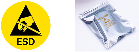
Electrostatic Discharge Protection and Handling

All electrostatic-sensitive components are handled in accordance with electrostatic discharge control procedures. The products are hermetically sealed in anti-static safe packaging to prevent electrostatic damage. Appropriate labeling is also applied for identification and traceability. This ensures product integrity during storage, handling and transportation.


ESD

Certifications & Memberships

Third-party certified, strict quality control. Our certification
  • ISO 9001: 2015
  • ISO 13485: 2016
  • ISO 14001: 2015
  • ISO 28000: 2007
  • ISO 45001: 2018
  • GB/T 27922-2011
  • SMTA
  • IPC
  • ESD
  • PSMA
53-CBSA-0.5X5.5X0.5 Image

53-CBSA-0.5X5.5X0.5

Leader Tech Inc.
98D-53-CBSA-0.5X5.5X0.5

Want a better price? Add to Cart and Submit RFQ now, we'll contact you immediately.

0 RFQ
Shopping cart (0 Items)
It is empty.
Compare List (0 Items)
It is empty.
Feedback

Your feedback matters! At Allelco, we value the user experience and strive to improve it constantly.
Please share your comments with us via our feedback form, and we'll respond promptly.
Thank you for choosing Allelco.

Subject
E-mail
Comments
Captcha
Drag or click to upload file
Upload File
types: .xls, .xlsx, .doc, .docx, .jpg, .png and .pdf.
Max file size: 10MB