View All

Please refer to the English Version as our Official Version.Return

Europe
France(Français) Germany(Deutsch) Italy(Italia) Russian(русский) Poland(polski) Czech(Čeština) Luxembourg(Lëtzebuergesch) Netherlands(Nederland) Iceland(íslenska) Hungarian(Magyarország) Spain(español) Portugal(Português) Turkey(Türk dili) Bulgaria(Български език) Ukraine(Україна) Greece(Ελλάδα) Israel(עִבְרִית) Sweden(Svenska) Finland(Svenska) Finland(Suomi) Romania(românesc) Moldova(românesc) Slovakia(Slovenská) Denmark(Dansk) Slovenia(Slovenija) Slovenia(Hrvatska) Croatia(Hrvatska) Serbia(Hrvatska) Montenegro(Hrvatska) Bosnia and Herzegovina(Hrvatska) Lithuania(lietuvių) Spain(Português) Switzerland(Deutsch) United Kingdom(English)
Asia/Pacific
Japan(日本語) Korea(한국의) Thailand(ภาษาไทย) Malaysia(Melayu) Singapore(Melayu) Vietnam(Tiếng Việt) Philippines(Pilipino)
Africa, India and Middle East
United Arab Emirates(العربية) Iran(فارسی) Tajikistan(فارسی) India(हिंदी) Madagascar(malaɡasʲ)
South America / Oceania
New Zealand(Maori) Brazil(Português) Angola(Português) Mozambique(Português)
North America
United States(English) Canada(English) Haiti(Ayiti) Mexico(español)
HomeProductsDiscrete Semiconductor ProductsDiodes - Zener - Single1N5366AE3/TR13
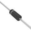
1N5366AE3/TR13 Image
Image may be representation.
See specifications for product details.
EXPRESS OPTION
Payment method

1N5366AE3/TR13 - Microchip Technology

Manufacturer Part Number
1N5366AE3/TR13
Manufacturer
Microchip Technology
Allelco Part Number
98D-1N5366AE3/TR13
Warranty
1 Year Allelco Warranty - Find out more
Stock Status:
44,448 pcs available, New & Original
Parts Description
DIODE ZENER 39V 5W T18
Package
T-18
Data sheet
1N5366AE3/TR13.pdf
RoHs Status
ROHS3 Compliant
Our certification
In stock: 44448
  • Unit Price: $0.99
  • Subtotal: $0.00

Want a better price?
Add to Cart and Submit RFQ now, we'll contact you immediately.

Quantity Unit Price Ext. Price
1+ $0.99 $0.99
The above prices does not include taxes and freight rates, which will be calculated on the order pages.


Specifications

1N5366AE3/TR13 Tech Specifications
Microchip Technology - 1N5366AE3/TR13 technical specifications, attributes, parameters and parts with similar specifications to Microchip Technology - 1N5366AE3/TR13

Product Attribute Attribute Value
Manufacturer Microchip Technology
Voltage - Zener (Nom) (Vz) 39 V
Voltage - Forward (Vf) (Max) @ If 1.2 V @ 1 A
Tolerance ±10%
Supplier Device Package T-18
Series -
Power - Max 5 W
Product Attribute Attribute Value
Package / Case T-18, Axial
Package Tape & Reel (TR)
Operating Temperature -65°C ~ 150°C
Mounting Type Through Hole
Impedance (Max) (Zzt) 14 Ohms
Current - Reverse Leakage @ Vr 500 nA @ 28.1 V
Base Product Number 1N5366

Environmental & Export Classifications

ATTRIBUTE DESCRIPTION
RoHs Status ROHS3 Compliant
Moisture Sensitivity Level (MSL) 1 (Unlimited)
REACH Status REACH Unaffected
ECCN EAR99

Frequently Asked Questions(FAQ)

What are the key electrical characteristics of the 1N5366AE3/TR13 Zener diode, and how do they influence high-voltage regulation in power supply designs?
The 1N5366AE3/TR13 features a nominal Zener voltage of 39 V with ±10% tolerance, meaning it operates effectively between 35.1 V and 42.9 V. Its maximum power rating is 5 W, which corresponds to a typical Zener current of approximately 128 mA under full load (5 W / 39 V). With an impedance (Zzt) of 14 ohms at rated conditions, this device offers moderate dynamic response for voltage clamping or reference applications. In power supply circuits requiring stable overvoltage protection, such as in telecom or industrial control systems, the 39 V breakdown ensures safe operation near 40 V rails while absorbing transient energy without thermal runaway. Engineers must ensure that peak instantaneous power does not exceed 5 W to maintain reliability.
How does the 1N5366AE3/TR13 compare to the 1N5366BG in terms of performance and application suitability for automotive environments?
While both share the same base product number and core electrical specifications—39 V Zener voltage, 5 W power dissipation, and T-18 package—the 1N5366AE3/TR13 is packaged in tape and reel format, making it more suitable for automated assembly processes. In contrast, the 1N5366BG typically appears in bulk packaging. For automotive applications requiring AEC-Q101 qualification, neither part may inherently meet all requirements unless explicitly certified; however, the 1N5366AE3/TR13’s RoHS3 compliance supports modern environmental standards often mandated in vehicle electronics. Thermal performance remains similar due to identical construction, so selection should prioritize supply chain logistics over intrinsic differences when operating within -65°C to 150°C range.
What design considerations arise when using the 1N5366AE3/TR13 in series with a resistive load to regulate voltage in a high-current switching regulator output stage?
The 1N5366AE3/TR13’s maximum power rating of 5 W limits its use in high-current scenarios; at 39 V, it can only safely handle about 128 mA continuously. If applied in a post-regulator clamp circuit protecting downstream ICs from overvoltage transients—such as during inductive kickback from motor drivers—the series resistor must drop excess voltage while ensuring the diode remains within its power envelope. For example, clamping a 48 V transient down to 39 V requires a resistor capable of dissipating (48 V – 39 V) × I_load + (I_transient)^2 × R_resistor. Additionally, leakage current of 500 nA at 28.1 V is negligible but becomes relevant in ultra-low-power designs where total system quiescent current matters.
Can the 1N5366AE3/TR13 be used interchangeably with 1N5366BRLG in precision analog reference circuits, and what trade-offs exist?
Although both diodes share the same 39 V Zener voltage and 5 W rating, the 1N5366BRLG is a lead-free version optimized for RoHS compliance and soldering compatibility, whereas the 1N5366AE3/TR13 includes additional traceability and reel packaging. However, their Zener impedance and temperature coefficients are nearly identical, suggesting comparable performance in reference applications. That said, the 1N5366AE3/TR13’s tighter manufacturing batch control (implied by reel-specific sourcing) may offer better consistency across production runs. Still, in precision analog stages demanding sub-1% stability, even minor variations in Zzt or thermal drift could affect accuracy—making calibration or trimming necessary regardless of substitution.
What is the significance of the 1N5366AE3/TR13’s moisture sensitivity level (MSL) rating of 1, and how does it impact storage and handling in mass production?
An MSL of 1 indicates that the 1N5366AE3/TR13 is not susceptible to moisture-related damage under normal ambient conditions, allowing unlimited shelf life without baking prior to reflow. This simplifies inventory management in high-volume manufacturing environments like consumer electronics assembly lines. Unlike components rated MSL 3 or higher, this diode does not require humidity conditioning before placement, reducing process overhead and minimizing risk of popcorning during reflow soldering. Consequently, engineers can confidently integrate it into automated pick-and-place workflows without additional drying steps, streamlining throughput for designs relying on through-hole mounting via the T-18 axial package.
How does the forward voltage drop of the 1N5366AE3/TR13 influence its use in bidirectional protection circuits compared to dedicated TVS diodes?
The 1N5366AE3/TR13 exhibits a forward voltage (Vf) of 1.2 V at 1 A, which is relatively high compared to low-Vf Schottky devices but acceptable for unidirectional clamping. In bidirectional transient suppression applications—such as ESD protection on RS-485 interfaces—this diode alone cannot provide symmetric response. Instead, it might be paired with another Zener or used asymmetrically. Its primary advantage lies in steady-state reverse regulation rather than fast transient absorption, where dedicated bidirectional TVS arrays offer superior response time (<1 ps) and lower clamping voltage. Thus, while the 1N5366AE3/TR13 can serve as a backup or secondary clamp, it is not ideal as a primary protection element in high-speed data lines.
What are the implications of substituting the 1N5366AE3/TR13 for the 1N5366BG in legacy industrial control panels with strict thermal cycling requirements?
Substitution between these parts is generally feasible due to matching electrical parameters—both deliver 39 V Zener voltage, 5 W dissipation, and operate across -65°C to 150°C. However, the 1N5366AE3/TR13’s reel packaging implies tighter lot-to-lot consistency, potentially offering better long-term reliability in harsh environments subject to repeated thermal stress. The absence of lead in the AE3/TR13 variant also reduces galvanic corrosion risks in humid installations. Nevertheless, if the original design specified through-hole T-18 mounting and manual soldering, the physical form factor difference between reel-fed and bulk-packed BG variants is minimal. Engineers should verify that solder joint integrity under thermal cycling exceeds 10,000 cycles, as the diode itself is robust up to 150°C junction temperature.
How does the Zener impedance (Zzt = 14 Ω) of the 1N5366AE3/TR13 affect dynamic regulation behavior in variable-load scenarios?
A Zzt of 14 Ω means that for every 1 mA change in Zener current around the knee point, the voltage varies by approximately 14 mV. While adequate for many clamping applications, this relatively high impedance makes the 1N5366AE3/TR13 less suitable for precision voltage references where tight load regulation is critical. In contrast, ultra-low-Zzt Zeners like the BZX84 series achieve values below 1 Ω. Therefore, in feedback loops or active regulators using this diode as a reference, additional buffering or compensation circuitry may be required to decouple load fluctuations. For passive overvoltage protection, however, the 14 Ω impedance is tolerable since the goal is to limit voltage spikes, not maintain constant output under varying loads.
What role does the 1N5366AE3/TR13 play in surge protection for battery-powered devices with regulated 39 V auxiliary rails?
In battery-backed systems where a 39 V auxiliary rail powers real-time clocks or non-volatile memory, the 1N5366AE3/TR13 serves as a reliable crowbar or shunt regulator against voltage transients from backfeeding or load dumps. Given its 5 W capability, it can absorb moderate energy surges without triggering protective fuses prematurely. For instance, during a short fault causing a brief 50 V spike, the diode conducts until current exceeds safe levels, prompting upstream protection to disconnect. Its through-hole T-18 package facilitates robust mechanical attachment for heat sinking if needed, though natural convection usually suffices given moderate power levels. Designers must ensure sufficient trace width and PCB layout margin to avoid localized heating during transient events.
Why might an engineer choose the 1N5366AE3/TR13 over integrated voltage supervisor ICs despite the latter offering programmable thresholds?
Integrated supervisors provide digital precision, monitoring multiple rails, and generating reset signals—advantages absent in discrete solutions like the 1N5366AE3/TR13. However, in simple, cost-sensitive designs requiring only hard overvoltage clamping at 39 V, the diode eliminates microcontroller dependency, reduces BOM count, and avoids firmware bugs. Its simplicity also minimizes propagation delay, enabling faster response to dangerous voltage excursions before microcontrollers initialize. Furthermore, the 1N5366AE3/TR13 functions reliably across the full industrial temperature range without calibration, unlike some ICs sensitive to supply noise or aging effects. This makes it preferable in rugged embedded systems where robustness outweighs programmability.
How does the 1N5366AE3/TR13’s reverse leakage current specification impact its use in high-impedance measurement circuits?
At 28.1 V, the reverse leakage current is specified at 500 nA, which is relatively low but may introduce offset errors in high-resistance sensor interfaces measuring voltages above 30 V. In precision instrumentation amplifiers or logarithmic converters using the diode as a reference, even nanoampere-level leakage can distort readings when multiplied by source impedance exceeding several megaohms. While acceptable in most power regulation contexts, designers should consider parallel guard rings or lower-leakage alternatives (e.g., surface-mount silicon Zeners) if signal fidelity is paramount. The 1N5366AE3/TR13 remains suitable for general-purpose protection where leakage has negligible effect on overall system performance.
What precautions should be taken when mounting the 1N5366AE3/TR13 on a PCB to ensure optimal thermal performance under continuous operation near its 5 W limit?
Since the 1N5366AE3/TR13 is housed in a T-18 axial package, its leads act as heat conductors. To maximize heat dissipation, the diode should be mounted perpendicular to airflow with adequate copper pour or ground plane contact at one end. Thermal resistance is not datasheeted but estimated at ~60–80°C/W based on similar packages; thus, dissipating 2 W continuously could raise junction temperature by 120–160°C above ambient. Engineers must derate power accordingly—ideally limiting operation to <3 W in enclosed spaces. Adhesive thermal pads or small heatsinks may be added for reliability in mission-critical applications, especially when ambient temperatures approach 70°C or higher.
How does the 1N5366AE3/TR13 perform in parallel configurations for increased current handling in redundant power paths?
Parallel Zeners rarely share current equally due to slight threshold mismatches, leading to uneven stress distribution. The 1N5366AE3/TR13’s ±10% tolerance means two units could have Vz values differing by up to 3.9 V, causing one to conduct heavily while the other remains off. Unless matched during procurement or actively balanced with ballast resistors, paralleling increases failure risk. For redundancy, better approaches include using dual diodes in anti-series configuration or selecting purpose-built multi-anode Zeners. Thus, while theoretically possible, practical implementations of the 1N5366AE3/TR13 in parallel require careful current-sharing analysis and margining beyond datasheet guarantees.
What environmental certifications support the suitability of the 1N5366AE3/TR13 for global deployment in consumer and medical equipment?
The 1N5366AE3/TR13 is RoHS3 compliant, meeting stricter hazardous substance restrictions including lead, mercury, cadmium, and certain phthalates. It is also REACH unaffected, indicating no SVHC content above regulatory thresholds. These certifications facilitate market access across Europe, North America, and Asia without additional documentation burdens. While not inherently medical-grade, its compliance with industrial and consumer safety standards allows integration into Class II medical peripherals where environmental regulations apply. However, functional safety certification (e.g., IEC 60601) still depends on full system validation, not just component compliance.
In what ways does the 1N5366AE3/TR13 complement flyback diode strategies in relay driver circuits operating at 39 V?
When driving inductive loads like relays at 39 V, freewheeling diodes (e.g., fast recovery types) manage energy stored in coil inductance. The 1N5366AE3/TR13, however, provides secondary protection by clamping any residual voltage spikes that bypass the primary diode due to parasitic capacitance or imperfect switching. Its slower response compared to ultra-fast diodes is acceptable here since the main task is sustained voltage regulation rather than nanosecond transient suppression. By positioning it across the relay terminals, the Zener prevents voltage overshoot from damaging MOSFETs or microcontrollers in the driver stage, adding a conservative safety layer without compromising switching speed.
How does the operating temperature range (-65°C to 150°C) of the 1N5366AE3/TR13 benefit aerospace or downhole instrumentation applications?
Aerospace and oil exploration systems often expose components to extreme temperatures—from cryogenic vacuum conditions to geothermal heat sources. The 1N5366AE3/TR13’s wide junction operating range ensures functionality across these environments without derating concerns. At -65°C, semiconductor mobility decreases slightly, increasing Zener voltage marginally, but within tolerance. Conversely, at 150°C, leakage current may rise modestly, yet still remain manageable due to the 500 nA spec at 28.1 V (well below thermal runaway thresholds). This broad envelope enables reliable use in satellites, deep-well sensors, or avionics where environmental extremes challenge conventional components, provided proper mechanical strain relief is implemented for the T-18 package.

Parts with Similar Specifications

The three parts on the right have similar specifications to Microchip Technology 1N5366AE3/TR13

Product Attribute 1N5366AE3/TR12 1N5365E3/TR13 1N5366AE3/TR8 1N5366BE3/TR12
Part Number 1N5366AE3/TR12 1N5365E3/TR13 1N5366AE3/TR8 1N5366BE3/TR12
Manufacturer Microchip Technology Microchip Technology Microchip Technology Microchip Technology
Voltage - Zener (Nom) (Vz) - - - -
Package / Case - 196-LFBGA 16-DIP (0.300', 7.62mm) 64-VFQFN Exposed Pad
Base Product Number - DAC34H84 MAX500 ADS62P42
Supplier Device Package - 196-NFBGA (12x12) 16-PDIP 64-VQFN (9x9)
Package - Tape & Reel (TR) Tube Tape & Reel (TR)
Mounting Type - Surface Mount Through Hole Surface Mount
Tolerance - - - -
Impedance (Max) (Zzt) - - - -
Power - Max - - - -
Operating Temperature - -40°C ~ 85°C 0°C ~ 70°C -40°C ~ 85°C
Voltage - Forward (Vf) (Max) @ If - - - -
Current - Reverse Leakage @ Vr - - - -
Series - - - -

1N5366AE3/TR13 Datasheet PDF

Download 1N5366AE3/TR13 pdf datasheets and Microchip Technology documentation for 1N5366AE3/TR13 - Microchip Technology.

Datasheets
1N5333B-1N5388B.pdf
PCN Assembly/Origin
Manufacturing Change 23/Feb/2021.pdf
Environmental Information
Microchip CA Prop65.pdf Microchip REACH.pdf Microchip RoHS.pdf

Customer Reviews

Evaluation: 10 Articles

  • ECUb***h
    Sep 22, 2026

    Used for repair of an older automotive ECU. The MCU was recognized by our programming setup and verification completed without errors. The repaired board now starts and communicates normally.

  • RS48***ieldTech
    Sep 16, 2026

    Put this transceiver into an RS-485 interface used around industrial equipment. Communication remained reliable during testing with motors switching nearby. Good result for the replacement board.

  • Logi***b_Chris
    Sep 8, 2026

    Purchased for a Cyclone III development project. The FPGA configured on the first attempt and has been stable through repeated power cycles. No problems with the I/O we are using.

  • Circ***FixerTom
    Sep 2, 2026

    Used this rectifier in a high-current power supply repair. Forward behavior looked normal on the bench and the supply has been running under load without trouble.

  • Retr***UWorks
    Aug 31, 2026

    Needed the exact ST10F269Z2Q6 for servicing an older control unit. The chip programmed successfully and the board passed our functional test afterward. Much easier than redesigning around a newer MCU.

  • Andr***PCBLab
    Aug 28, 2026

    I needed this ADC for an older data acquisition board. Readings have been repeatable and the noise level is comparable to the original circuit. Happy with the purchase.

  • Leat***O'Keefe
    Aug 20, 2026

    one of my hobbies is skydiving. and when i'm skydiving this works great.

  • Ilen***
    Aug 20, 2026

    This product works considerably well. It secretly improves my basketball by a lot.

  • Indu***ialPower
    Aug 17, 2026

    Installed this IGBT module in a power conversion cabinet. Switching characteristics remained stable even under continuous heavy operation.

  • Nikh***ech
    Aug 13, 2026

    Great low-power MCU for portable equipment. Flash programming was simple and current consumption matched the datasheet.

Write a Review

Your Email address will not be published.

Shipment

Delivery Time

In-stock items can be shipped within 24 hours. Some parts will be arranged for delivery within 1-2 days from the date all items arrive at our warehouse. And Allelco ships order once a day at about 17:00, except Sunday. Once the goods are shipped, the estimated delivery time depends on the shipping methods and Delivery destination. The table below shows are the logistic time for some common countries.

Delivery Cost

  1. Use your express account for shipment if you have one.
  2. Use our account for the shipment. Refer to the table below for the approximate charges.
(Different time frame / countries / package size has different price.)

Delivery Method

  1. Global Common Shipment by DHL / UPS / FedEx / TNT / EMS / SF we support.
  2. Others more shipping ways, please get in touch with your customer manager.

Common Countries Logistic Time Reference
Region Country Logistic Time(Day)
America United States 5
Brazil 7
Europe Germany 5
United Kingdom 4
Italy 5
Oceania Australia 6
New Zealand 5
Asia India 4
Japan 4
Middle East Israel 6
DHL & FedEx Shipment Charges Reference
Shipment charges(KG) Reference DHL(USD$)
0.00kg-1.00kg USD$30.00 - USD$60.00
1.00kg-2.00kg USD$40.00 - USD$80.00
2.00kg-3.00kg USD$50.00 - USD$100.00
Note:
The above table is for reference only. There may have some data bias for the uncontrollable factors.
Contact us if you have any questions.
  • QC (Quality Warranty)
  • Payment Support
  • Packaging
  • Certifications & Memberships

QC (Quality Warranty)

Allelco is committed to exceeding customer expectations through customer service excellence, order accuracy, and on-time delivery.
This is achieved through our commitment to the continual improvement of our processes, services, and products.


Strict quality inspection builds a solid foundation for electronic component quality.
  1. Visual inspection
  2. Performance testing and reliability verification
  3. Standardized full-process testing
  4. Precise control of every parameter
We eliminate defective components and ensure the stable operation of electronic devices through professional quality standards.

Payment Support

The payment method can be chosen from the methods shown below: Wire Transfer (T/T, Bank Transfer), Western Union, Credit card, PayPal.
  • HKBea
  • Paypal
  • MasterCard
  • Western-Union
  • VISA
Stable Delivery, Sincere Partnership — Your Faithful Supply Chain Partner
  • Efficient Supply Management
  • Cost-Saving Procurement
  • Fast Sourcing & Delivery
Contact us if you have any questions.

Packaging

Electrostatic Discharge Protection and Handling

All electrostatic-sensitive components are handled in accordance with electrostatic discharge control procedures. The products are hermetically sealed in anti-static safe packaging to prevent electrostatic damage. Appropriate labeling is also applied for identification and traceability. This ensures product integrity during storage, handling and transportation.


ESD

Certifications & Memberships

Third-party certified, strict quality control. Our certification
  • ISO 9001: 2015
  • ISO 13485: 2016
  • ISO 14001: 2015
  • ISO 28000: 2007
  • ISO 45001: 2018
  • GB/T 27922-2011
  • SMTA
  • IPC
  • ESD
  • PSMA
1N5366AE3/TR13 Image

1N5366AE3/TR13

Microchip Technology
98D-1N5366AE3/TR13

Want a better price? Add to Cart and Submit RFQ now, we'll contact you immediately.

0 RFQ
Shopping cart (0 Items)
It is empty.
Compare List (0 Items)
It is empty.
Feedback

Your feedback matters! At Allelco, we value the user experience and strive to improve it constantly.
Please share your comments with us via our feedback form, and we'll respond promptly.
Thank you for choosing Allelco.

Subject
E-mail
Comments
Captcha
Drag or click to upload file
Upload File
types: .xls, .xlsx, .doc, .docx, .jpg, .png and .pdf.
Max file size: 10MB










