View All

Please refer to the English Version as our Official Version.Return

Europe
France(Français) Germany(Deutsch) Italy(Italia) Russian(русский) Poland(polski) Czech(Čeština) Luxembourg(Lëtzebuergesch) Netherlands(Nederland) Iceland(íslenska) Hungarian(Magyarország) Spain(español) Portugal(Português) Turkey(Türk dili) Bulgaria(Български език) Ukraine(Україна) Greece(Ελλάδα) Israel(עִבְרִית) Sweden(Svenska) Finland(Svenska) Finland(Suomi) Romania(românesc) Moldova(românesc) Slovakia(Slovenská) Denmark(Dansk) Slovenia(Slovenija) Slovenia(Hrvatska) Croatia(Hrvatska) Serbia(Hrvatska) Montenegro(Hrvatska) Bosnia and Herzegovina(Hrvatska) Lithuania(lietuvių) Spain(Português) Switzerland(Deutsch) United Kingdom(English)
Asia/Pacific
Japan(日本語) Korea(한국의) Thailand(ภาษาไทย) Malaysia(Melayu) Singapore(Melayu) Vietnam(Tiếng Việt) Philippines(Pilipino)
Africa, India and Middle East
United Arab Emirates(العربية) Iran(فارسی) Tajikistan(فارسی) India(हिंदी) Madagascar(malaɡasʲ)
South America / Oceania
New Zealand(Maori) Brazil(Português) Angola(Português) Mozambique(Português)
North America
United States(English) Canada(English) Haiti(Ayiti) Mexico(español)
HomeProductsIntegrated Circuits (ICs)Embedded - MicrocontrollersPIC16F726T-I/SS
PIC16F726T-I/SS Image
Image may be representation.
See specifications for product details.
EXPRESS OPTION
Payment method

PIC16F726T-I/SS - Microchip Technology

Manufacturer Part Number
PIC16F726T-I/SS
Manufacturer
Microchip Technology
Allelco Part Number
32D-PIC16F726T-I/SS
Warranty
1 Year Allelco Warranty - Find out more
Stock Status:
23,266 pcs available, New & Original
Parts Description
IC MCU 8BIT 14KB FLASH 28SSOP
Package
28-SSOP
Data sheet
PIC16F726T-I/SS.pdf
RoHs Status
ROHS3 Compliant
Our certification
In stock: 23266

Required fields are indicated by an asterisk (*)
Please send RFQ, we will respond immediately.

Quantity

Specifications

PIC16F726T-I/SS Tech Specifications
Microchip Technology - PIC16F726T-I/SS technical specifications, attributes, parameters and parts with similar specifications to Microchip Technology - PIC16F726T-I/SS

Product Attribute Attribute Value
Manufacturer Microchip Technology
Voltage - Supply (Vcc/Vdd) 1.8V ~ 5.5V
Supplier Device Package 28-SSOP
Speed 20MHz
Series PIC® XLP™ 16F
RAM Size 368 x 8
Program Memory Type FLASH
Program Memory Size 14KB (8K x 14)
Peripherals Brown-out Detect/Reset, POR, PWM, WDT
Package / Case 28-SSOP (0.209", 5.30mm Width)
Package Tape & Reel (TR)
Product Attribute Attribute Value
Oscillator Type Internal
Operating Temperature -40°C ~ 85°C (TA)
Number of I/O 25
Mounting Type Surface Mount
EEPROM Size -
Data Converters A/D 11x8b
Core Size 8-Bit
Core Processor PIC
Connectivity I²C, SPI, UART/USART
Base Product Number PIC16F726

Environmental & Export Classifications

ATTRIBUTE DESCRIPTION
RoHs Status ROHS3 Compliant
Moisture Sensitivity Level (MSL) 1 (Unlimited)
REACH Status REACH Unaffected
ECCN EAR99
HTSUS 8542.31.0001

Parts Introduction

PIC16F726T-I/SS Image
PIC16F726T-I/SS (1)

Manufacturer Part Number

PIC16F726T-I/SS

Manufacturer

Microchip Technology

Introduction

The PIC16F726T-I/SS is an 8-bit microcontroller from Microchip Technology, integrated with Enhanced Mid-range Core and designed for versatile, low-power, and high-performance embedded applications.

Product Features and Performance

8-Bit CPU architecture

High execution speed up to 20MHz

Extensive connectivity support including I2C, SPI, UART/USART

Integrated peripherals such as Brown-out Detect/Reset, POR, PWM, WDT enhance functionality

25 programmable I/O pins for flexible device interfacing

14KB of FLASH memory enables robust program storage

11-channel, 8-bit Analog-to-Digital Converter

Internal oscillator for simplified clock management

Product Advantages

Low power consumption with Microchip’s XLP technology for energy efficiency

High integration reduces external components and system cost

Wide voltage range support (1.8V to 5.5V) facilitates compatibility with various power supplies

Robust temperature range (-40°C to 85°C) ensures reliability in harsh environments

Key Technical Parameters

Core Size: 8-Bit

Speed: 20MHz

Program Memory Size: 14KB (8K x 14)

RAM Size: 368 x 8

Operating Voltage: 1.8V to 5.5V

Data Converters: A/D 11x8b

Operating Temperature: -40°C to 85°C
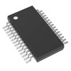
Package: 28-SSOP

Quality and Safety Features

Brown-out Detect/Reset for protection against voltage dips

Power-on Reset minimizes startup errors

Watchdog Timer for system reliability and recovery

Compatibility

Compatible with Microchip development tools for easy programming and debugging

Wide range of interface options for diverse external devices

Application Areas

Industrial control systems

Consumer electronics

Automotive applications

IoT devices

Product Lifecycle

Status: Active

Not nearing discontinuation, with ongoing support and availability from Microchip Technology

Several Key Reasons to Choose This Product

Energy-efficient design with Extended Low-Power (XLP) technology

Comprehensive feature set supports complex applications without additional components

Flexible programming and abundant memory for both simple and advanced tasks

Strong community and manufacturer support facilitates development and troubleshooting

Highly versatile for a broad range of applications, ensuring a good fit for many projects

Frequently Asked Questions(FAQ)

How does the PIC16F726T-I/SS handle power management during low-voltage operation, and what impact does this have on system reliability in battery-powered applications?
The PIC16F726T-I/SS supports ultra-low-power operation across a supply range of 1.8V to 5.5V, making it suitable for energy-constrained environments. Its PIC® XLP™ architecture reduces active current consumption to as low as 30 µA/MHz in Run mode, with standby current below 100 nA when using the internal oscillator. This efficiency directly extends battery life in devices like remote sensors or wearables. However, designers must account for voltage droop during wake-up transients, which can trigger brown-out resets if not managed with adequate decoupling capacitance and stable VDD ramping.
What are the key differences between the PIC16F726T-I/SS and the PIC16F726-I/SS in terms of thermal and manufacturing traceability, and how might this affect long-term deployment?
While both parts share identical electrical characteristics—including 14KB Flash, 25 I/O pins, and 28-SSOP packaging—the suffix "T" in the PIC16F726T-I/SS indicates a tape-and-reel packaging variant optimized for automated pick-and-place assembly. This does not alter functionality but ensures compatibility with high-volume SMT lines. From a reliability standpoint, neither variant introduces significant thermal differences due to shared die size and package outline; however, the T-variant’s MSL rating of 1 (unlimited floor life) simplifies inventory handling without risking moisture sensitivity during storage.
Can the PIC16F726T-I/SS reliably operate at the lower end of its supply voltage range, and what design precautions are necessary to maintain ADC accuracy?
Yes, the PIC16F726T-I/SS is specified for stable operation down to 1.8V, but analog performance degrades near minimum VDD due to reduced reference stability and increased noise susceptibility. At 1.8V, the onboard 11-channel 8-bit ADC may exhibit ±2 LSB integral nonlinearity under typical conditions, whereas at 5.0V it achieves ±1 LSB. To preserve measurement integrity, designers should ensure clean power delivery with <50 mVpp ripple, use bypass capacitors close to VDD/VSS pins, and avoid switching digital loads during critical conversions. Additionally, internal bandgap reference accuracy drops about 0.1% per degree Celsius above 25°C, necessitating temperature calibration if high precision is required.
How does the internal oscillator configuration affect timing predictability in the PIC16F726T-I/SS, and what alternatives exist for applications requiring tighter clock tolerance?
The PIC16F726T-I/SS uses an internal 20 MHz RC oscillator that typically drifts by ±1% over temperature (-40°C to +85°C) and aging. While sufficient for many non-critical tasks like UART baud rate generation, this variability can cause communication errors in synchronous protocols such as SPI master-slave links where clock phase alignment matters. For improved accuracy, external crystals or ceramic resonators can be used via the OSC1/OSC2 pins, enabling ±30 ppm stability. When switching from internal to external clock sources, software must reconfigure PLL settings and recalibrate peripheral timing registers to maintain synchronization.
What considerations apply when interfacing multiple peripherals simultaneously on the PIC16F726T-I/SS, particularly regarding shared resources like the UART or PWM modules?
The PIC16F726T-I/SS integrates one UART/USART module capable of full-duplex communication up to 57.6 kbps at 20 MHz, but only one instance exists per device. Simultaneous use of multiple serial interfaces requires either bit-banging software implementations or careful multiplexing. Similarly, while it features four PWM channels, they share a single timer base, limiting independent frequency control. Designers must prioritize resource allocation based on real-time requirements: for example, assigning the hardware UART to primary data logging while implementing a custom I²C slave routine using interrupts. Failure to manage these constraints can lead to missed deadlines or corrupted frames under heavy traffic.
Is the EEPROM memory available in the PIC16F726T-I/SS, and how should persistent configuration data be handled if non-volatile storage is needed?
No, the PIC16F726T-I/SS does not include dedicated EEPROM memory. Instead, user data must be stored in Flash program memory using emulated EEPROM techniques. This method writes data in 32-byte blocks via the Flash memory controller, but each erase/write cycle limits endurance to approximately 100,000 operations per block. Therefore, frequent updates to configuration parameters should be buffered in RAM and written less often—ideally once per power cycle or after significant state changes. Wear leveling algorithms become essential for longevity, especially in systems requiring frequent parameter adjustments.
How does the watchdog timer implementation in the PIC16F726T-I/SS compare to other PIC16F series MCUs, and what best practices reduce unintended resets?
Like most PIC16F family members, the PIC16F726T-I/SS includes a programmable watchdog timer (WDT) that resets the device if not cleared within the set period, typically ranging from 18 ms to 71 seconds depending on configuration bits. Unlike some enhanced mid-range PICs, it lacks windowed WDT modes, so periodic servicing during normal execution suffices. Best practices include disabling global interrupts before WDT service routines, ensuring no infinite loops occur in main() logic, and validating stack usage to prevent corruption-induced hangs. In addition, enabling Power-on Reset (POR) and Brown-out Detect (BOD) together provides layered recovery against voltage anomalies.
What trade-offs exist between using internal versus external oscillators in the PIC16F726T-I/SS, and how do they influence system cost and complexity?
Choosing the internal 20 MHz oscillator minimizes external components and PCB real estate, reducing BOM cost by eliminating crystal and load capacitors. However, it introduces timing uncertainty that may require software compensation in time-sensitive applications. Conversely, an external crystal offers superior stability (±30 ppm vs. ±1%) and enables precise baud rates without divisor adjustments, improving protocol compliance. The added cost includes two passive components plus routing considerations, but simplifies firmware development. Ultimately, the decision hinges on whether application-level tolerance for clock drift justifies the savings in component count and layout simplicity.
How should the ADC inputs on the PIC16F726T-I/SS be managed when measuring signals with fast transients, and what sampling strategies optimize signal fidelity?
The 8-bit ADC on the PIC16F726T-I/SS samples at up to 50 ksps internally, but effective resolution diminishes with rapid input changes due to settling time limitations of the internal sample-and-hold circuit. For transient-rich signals—such as motor current sensing or capacitive touch inputs—designers should enable the ADC’s internal buffer and allow at least 4 TAD (typically 800 ns at 20 MHz) between acquisition start and conversion begin. Additionally, oversampling and averaging can improve apparent resolution; for instance, taking eight consecutive samples and discarding outliers yields better results than single-shot reads. Analog front-end filtering using RC networks tuned to the expected bandwidth further enhances accuracy by suppressing aliasing and glitch injection.
What role does the Program Memory Type (FLASH) play in reprogramming the PIC16F726T-I/SS, and what safeguards prevent accidental code corruption during field updates?
FLASH memory allows in-system programming (ISP) without removing the microcontroller from the target board, enabling firmware updates post-deployment. Each sector erase/write cycle takes approximately 4 ms, supporting rapid iterative development. However, improper handling—such as power loss during write—can corrupt code. To mitigate risk, implement a bootloader with dual-image staging: new firmware is written to a separate sector, then validated before switching execution vectors. Watchdog timers remain disabled during update sequences, and checksums (e.g., CRC-16) verify integrity before jump execution. These practices ensure robust recovery even if partial writes occur.
How does the operating temperature range (-40°C to +85°C) of the PIC16F726T-I/SS affect oscillator drift and analog performance in industrial environments?
Across the extended temperature range, the internal oscillator frequency can vary by up to ±2%, impacting timing-dependent peripherals like PWM duty cycles and communication baud rates. Similarly, the ADC’s reference voltage exhibits nonlinear drift with temperature, degrading absolute accuracy in precision measurements. Industrial deployments often compensate by calibrating endpoints during manufacturing or using lookup tables in firmware. Where extreme reliability is critical, external temperature-stable oscillators are preferred despite added cost. Alternatively, periodic self-calibration routines leveraging known reference voltages (e.g., internal bandgap) can dynamically correct for drift.
What are the implications of selecting the 28-SSOP package for high-density PCB designs using the PIC16F726T-I/SS, and how does pinout arrangement influence signal integrity?
The 28-pin SSOP package (5.3 mm width) occupies moderate board space, suitable for compact embedded systems but challenging for fine-pitch routing. Pin assignment follows Microchip’s standard layout, placing power, ground, and analog inputs near the center to minimize loop inductance. However, adjacent digital and analog pins may couple noise, so careful layer stacking and guard rings around sensitive traces are advised. Thermal vias under the package enhance heat dissipation, though peak junction temperatures remain within limits given the part’s low power envelope. For designs exceeding 10 layers, consider alternative packages like QFN for better thermal and EMI performance.

Parts with Similar Specifications

The three parts on the right have similar specifications to Microchip Technology PIC16F726T-I/SS

Product Attribute PIC16F726-I/SS PIC16F726T-I/MV PIC16F726-E/SS PIC16F726-I/SO
Part Number PIC16F726-I/SS PIC16F726T-I/MV PIC16F726-E/SS PIC16F726-I/SO
Manufacturer Microchip Technology Microchip Technology Microchip Technology Microchip Technology
EEPROM Size - - - -
Core Size - - - -
Package - Tape & Reel (TR) Tube Tape & Reel (TR)
Base Product Number - DAC34H84 MAX500 ADS62P42
Core Processor - - - -
Series - - - -
Mounting Type - Surface Mount Through Hole Surface Mount
Peripherals - - - -
Program Memory Size - - - -
Program Memory Type - - - -
Operating Temperature - -40°C ~ 85°C 0°C ~ 70°C -40°C ~ 85°C
Number of I/O - - - -
Connectivity - - - -
Voltage - Supply (Vcc/Vdd) - - - -
RAM Size - - - -
Supplier Device Package - 196-NFBGA (12x12) 16-PDIP 64-VQFN (9x9)
Package / Case - 196-LFBGA 16-DIP (0.300', 7.62mm) 64-VFQFN Exposed Pad
Speed - - - -
Oscillator Type - - - -
Data Converters - - - -

PIC16F726T-I/SS Datasheet PDF

Download PIC16F726T-I/SS pdf datasheets and Microchip Technology documentation for PIC16F726T-I/SS - Microchip Technology.

Datasheets
Next Generation Peripherals Brochure.pdf PIC16(L)F72x Datasheet.pdf PIC16F72x Brochure.pdf Tips N Tricks Guide.pdf
PCN Design/Specification
Copper Bond Wire 17/Dec/2014.pdf
PCN Packaging
Label and Packing Changes 23/Sep/2015.pdf Reel Design Update 07/May/2015.pdf
PCN Assembly/Origin
Mult Devices 14/Jun/2018.pdf

Customer Reviews

Evaluation: 10 Articles

  • Dani***alkerTech
    Jun 1, 2026

    Product works, but setup took more effort than expected. Once configured the MCU ran reliably, although documentation support felt older compared with newer platforms. Fine for maintenance projects.

  • Yuki***aka88
    May 26, 2026

    信号通信プロジェクトでこのRS-485トランシーバーを使用しました。設置は簡単で、長距離ケーブルでも通信は安定していました。消費電力も、以前使用していたものより低くなっています。

  • Stev***aker
    May 20, 2026

    Solid diode for power rectification. Works well in switching circuits.

  • Bran***Lewis
    May 11, 2026

    Compact FPGA with good performance. Suitable for basic signal processing tasks.

  • Oliv***arris
    May 7, 2026

    Reliable I/O expander. Works well in embedded control applications.

  • Jess***Jones
    Apr 17, 2026

    It offers good value for the price, and the specifications match the description. I’ve been using it for two days with no issues, and I’ll definitely buy it again if I need it in the future.

  • Mich***Smith
    Apr 17, 2026

    Shipping was on time, the component pins are neatly aligned, and I tested 10 of them with a multimeter—all readings were within the specified range. Highly recommended.

  • Aman***arris
    Apr 3, 2026

    It was great—the entire process, from placing the order to receiving the package, went very smoothly. The components were consistent, the price was fair, and I had a very pleasant shopping experience.

  • Mike***nch
    Apr 3, 2026

    Better than expected! The resistance and capacitance readings were spot-on, and it passed the test on the first try. The service was reliable, and the packaging was thoughtful—I highly recommend it.

  • Daic***K.
    Mar 23, 2026

    Very good. No issue after long time testing.

Write a Review

Your Email address will not be published.

Shipment

Delivery Time

In-stock items can be shipped within 24 hours. Some parts will be arranged for delivery within 1-2 days from the date all items arrive at our warehouse. And Allelco ships order once a day at about 17:00, except Sunday. Once the goods are shipped, the estimated delivery time depends on the shipping methods and Delivery destination. The table below shows are the logistic time for some common countries.

Delivery Cost

  1. Use your express account for shipment if you have one.
  2. Use our account for the shipment. Refer to the table below for the approximate charges.
(Different time frame / countries / package size has different price.)

Delivery Method

  1. Global Common Shipment by DHL / UPS / FedEx / TNT / EMS / SF we support.
  2. Others more shipping ways, please get in touch with your customer manager.

Common Countries Logistic Time Reference
Region Country Logistic Time(Day)
America United States 5
Brazil 7
Europe Germany 5
United Kingdom 4
Italy 5
Oceania Australia 6
New Zealand 5
Asia India 4
Japan 4
Middle East Israel 6
DHL & FedEx Shipment Charges Reference
Shipment charges(KG) Reference DHL(USD$)
0.00kg-1.00kg USD$30.00 - USD$60.00
1.00kg-2.00kg USD$40.00 - USD$80.00
2.00kg-3.00kg USD$50.00 - USD$100.00
Note:
The above table is for reference only. There may have some data bias for the uncontrollable factors.
Contact us if you have any questions.
  • QC (Quality Warranty)
  • Payment Support
  • Packaging
  • Certifications & Memberships

QC (Quality Warranty)

Allelco is committed to exceeding customer expectations through customer service excellence, order accuracy, and on-time delivery.
This is achieved through our commitment to the continual improvement of our processes, services, and products.


Strict quality inspection builds a solid foundation for electronic component quality.
  1. Visual inspection
  2. Performance testing and reliability verification
  3. Standardized full-process testing
  4. Precise control of every parameter
We eliminate defective components and ensure the stable operation of electronic devices through professional quality standards.

Payment Support

The payment method can be chosen from the methods shown below: Wire Transfer (T/T, Bank Transfer), Western Union, Credit card, PayPal.
  • HKBea
  • Paypal
  • MasterCard
  • Western-Union
  • VISA
Stable Delivery, Sincere Partnership — Your Faithful Supply Chain Partner
  • Efficient Supply Management
  • Cost-Saving Procurement
  • Fast Sourcing & Delivery
Contact us if you have any questions.

Packaging

Electrostatic Discharge Protection and Handling

All electrostatic-sensitive components are handled in accordance with electrostatic discharge control procedures. The products are hermetically sealed in anti-static safe packaging to prevent electrostatic damage. Appropriate labeling is also applied for identification and traceability. This ensures product integrity during storage, handling and transportation.


ESD

Certifications & Memberships

Third-party certified, strict quality control. Our certification
  • ISO 9001: 2015
  • ISO 13485: 2016
  • ISO 14001: 2015
  • ISO 28000: 2007
  • ISO 45001: 2018
  • GB/T 27922-2011
  • SMTA
  • IPC
  • ESD
  • PSMA
PIC16F726T-I/SS Image

PIC16F726T-I/SS

Microchip Technology
32D-PIC16F726T-I/SS

Want a better price? Add to Cart and Submit RFQ now, we'll contact you immediately.

0 RFQ
Shopping cart (0 Items)
It is empty.
Compare List (0 Items)
It is empty.
Feedback

Your feedback matters! At Allelco, we value the user experience and strive to improve it constantly.
Please share your comments with us via our feedback form, and we'll respond promptly.
Thank you for choosing Allelco.

Subject
E-mail
Comments
Captcha
Drag or click to upload file
Upload File
types: .xls, .xlsx, .doc, .docx, .jpg, .png and .pdf.
Max file size: 10MB