View All

Please refer to the English Version as our Official Version.Return

Europe
France(Français) Germany(Deutsch) Italy(Italia) Russian(русский) Poland(polski) Czech(Čeština) Luxembourg(Lëtzebuergesch) Netherlands(Nederland) Iceland(íslenska) Hungarian(Magyarország) Spain(español) Portugal(Português) Turkey(Türk dili) Bulgaria(Български език) Ukraine(Україна) Greece(Ελλάδα) Israel(עִבְרִית) Sweden(Svenska) Finland(Svenska) Finland(Suomi) Romania(românesc) Moldova(românesc) Slovakia(Slovenská) Denmark(Dansk) Slovenia(Slovenija) Slovenia(Hrvatska) Croatia(Hrvatska) Serbia(Hrvatska) Montenegro(Hrvatska) Bosnia and Herzegovina(Hrvatska) Lithuania(lietuvių) Spain(Português) Switzerland(Deutsch) United Kingdom(English)
Asia/Pacific
Japan(日本語) Korea(한국의) Thailand(ภาษาไทย) Malaysia(Melayu) Singapore(Melayu) Vietnam(Tiếng Việt) Philippines(Pilipino)
Africa, India and Middle East
United Arab Emirates(العربية) Iran(فارسی) Tajikistan(فارسی) India(हिंदी) Madagascar(malaɡasʲ)
South America / Oceania
New Zealand(Maori) Brazil(Português) Angola(Português) Mozambique(Português)
North America
United States(English) Canada(English) Haiti(Ayiti) Mexico(español)
HomeProductsSwitchesLimit SwitchesSS-01GL2-ET
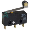
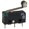
SS-01GL2-ET Image
Image may be representation.
See specifications for product details.
EXPRESS OPTION
Payment method

SS-01GL2-ET - Omron Electronics Inc-EMC Div

Manufacturer Part Number
SS-01GL2-ET
Manufacturer
Omron Electronic Components
Allelco Part Number
98D-SS-01GL2-ET
Warranty
1 Year Allelco Warranty - Find out more
Stock Status:
41,725 pcs available, New & Original
Parts Description
SWITCH SNAP ACT SPDT 100MA 125V
Package
Bulk
Data sheet
SS-01GL2-ET.pdf
RoHs Status
RoHS Compliant
Our certification
In stock: 41725
  • Unit Price: $2.788
  • Subtotal: $0.00

Want a better price?
Add to Cart and Submit RFQ now, we'll contact you immediately.

Quantity Unit Price Ext. Price
1+ $2.788 $2.79
The above prices does not include taxes and freight rates, which will be calculated on the order pages.


Specifications

SS-01GL2-ET Tech Specifications
Omron Electronics Inc-EMC Div - SS-01GL2-ET technical specifications, attributes, parameters and parts with similar specifications to Omron Electronics Inc-EMC Div - SS-01GL2-ET

Product Attribute Attribute Value
Manufacturer Omron Electronic Components
Voltage Rating - DC 30 V
Voltage Rating - AC 125 V
Termination Style Quick Connect - 0.110' (2.8mm)
Switch Function On-Mom
Series SS
Release Force 1.020gf
Pretravel -
Package Bulk
Overtravel 0.047' (1.2mm)
Operating Temperature -25°C ~ 85°C
Operating Position 0.571' (14.5mm)
Product Attribute Attribute Value
Operating Force 8.158gf
Mounting Type Chassis Mount
Mechanical Life 30,000,000 Cycles
Ingress Protection IP40
Features -
Electrical Life 200,000 Cycles
Differential Travel 0.031' (0.8mm)
Current Rating (Amps) 100mA (AC/DC)
Circuit SPDT
Base Product Number SS-01GL
Actuator Type Lever, Roller

Environmental & Export Classifications

ATTRIBUTE DESCRIPTION
RoHs Status RoHS Compliant
Moisture Sensitivity Level (MSL) Not Applicable
ECCN EAR99
HTSUS 8536.50.7000

Frequently Asked Questions(FAQ)

What is the key difference between the SS-01GL2-ET snap action switch and a standard momentary push button for chassis-mounted applications?
The SS-01GL2-ET is a snap action switch with a lever and roller actuator designed for positive tactile feedback and repeatable engagement. Unlike a standard push button, the SS-01GL2-ET uses a spring-loaded mechanism that creates a distinct snap point during actuation, reducing contact bounce and improving signal reliability. The lever configuration of the SS-01GL2-ET allows operation from multiple angles and is particularly suited for applications requiring consistent force feedback across 200,000 electrical cycles. The roller actuator variant of the SS-01GL2-ET accommodates cam-driven or edge-triggered activation patterns that simple push buttons cannot reliably execute.
Can the SS-01GL2-ET handle both AC and DC applications, and what voltage derating should be applied when switching between them?
The SS-01GL2-ET is rated for 125V AC and 30V DC, with the same 100mA current limit applied to both. This asymmetry reflects different load behavior: AC loads tolerate higher voltage due to zero-crossing current extinction, while DC loads present sustained arcing risk during contact separation. When designing with the SS-01GL2-ET, AC applications can utilize the full 125V rating, but DC circuits must be derated to 30V maximum. For mixed-signal environments using the SS-01GL2-ET, the lower DC rating becomes the design constraint if both voltage types appear in different load branches. This voltage disparity is common in snap action switches and reflects contact material limitations rather than component reliability concerns.
How does the differential travel specification of 0.031" on the SS-01GL2-ET affect noise immunity in industrial control circuits?
The differential travel of 0.031" (0.8mm) on the SS-01GL2-ET defines the hysteresis distance between switch closure and opening points. This spacing prevents chatter and transition instability when the actuator encounters vibration or hesitant operator input. In industrial environments where mechanical vibration is present, the differential travel of the SS-01GL2-ET acts as a mechanical filter, requiring the actuator to fully release before the switch can re-engage. This specification is particularly valuable in equipment with continuous vibration, where a switch with minimal differential travel would generate false transitions. The 0.031" differential on the SS-01GL2-ET is conservative for industrial use, providing robust noise immunity without excessive actuator travel requirements.
What is the practical lifespan difference between the 200,000 electrical cycle rating and the 30,000,000 mechanical cycle rating of the SS-01GL2-ET?
The SS-01GL2-ET exhibits a 150× difference between electrical and mechanical cycle ratings because electrical life is limited by contact erosion and arc damage, while mechanical life reflects spring fatigue and structural integrity. A 200,000 electrical cycle limit assumes typical industrial loads within the 100mA and voltage specifications; exceeding these parameters dramatically reduces the electrical life of the SS-01GL2-ET. The 30,000,000 mechanical cycle rating indicates the actuator linkage and spring can withstand that many strokes without physical failure. In practice, the SS-01GL2-ET will reach electrical end-of-life long before mechanical failure occurs if operated within rated electrical parameters. For applications operating continuously at 5 cycles per minute, the SS-01GL2-ET's electrical rating provides approximately 666 hours of service before contact degradation becomes probable.
How does the 8.158gf operating force of the SS-01GL2-ET compare to typical user ergonomic expectations for manual lever switches?
The 8.158gf (approximately 80mN) operating force of the SS-01GL2-ET is relatively light and sits below common ergonomic fatigue thresholds for repeated manual actuation. This force level is significantly lower than industrial push buttons (typically 150–300gf) and reflects the mechanical advantage provided by the lever arm design. The low operating force of the SS-01GL2-ET enables reliable actuation by users with reduced manual dexterity and reduces finger fatigue during high-frequency manual operation. The 1.020gf release force creates a 8× differential, which is characteristic of snap action mechanisms and ensures the SS-01GL2-ET will not inadvertently remain partially actuated. For handheld or frequently touched applications, the light actuation force of the SS-01GL2-ET is a design advantage, though it may require mechanical guarding to prevent accidental activation in high-vibration environments.
Is the SS-01GL2-ET suitable for sealed or outdoor enclosures, and what does the IP40 rating actually protect against?
The SS-01GL2-ET carries an IP40 ingress protection rating, which means it resists splashed water and larger solid objects (>1mm) but is not sealed against dust ingress or directed water jets. IP40 on the SS-01GL2-ET indicates the actuator opening allows access to internal contacts; the switch is suitable for indoor industrial control panels and dry environments but not for washdown applications or outdoor weather exposure. If the SS-01GL2-ET must operate in wet or dusty conditions, it requires external mounting in a protective enclosure or polycarbonate guard. The IP40 rating does not imply corrosion resistance; the SS-01GL2-ET's contacts may oxidize in high-humidity environments without secondary protection such as conformal coating or periodic contact cleaning.
Why does the SS-01GL2-ET specify a 14.5mm operating position rather than actuator travel, and how does this affect mechanical integration?
The 14.5mm operating position on the SS-01GL2-ET defines the absolute displacement of the lever or roller from the neutral (unactuated) state to the point where electrical contact closure occurs. This is distinct from actuator travel because snap action switches use mechanical leverage: the full lever movement may exceed the contact travel by a significant margin. The 14.5mm operating position of the SS-01GL2-ET tells the designer how much physical space must be reserved for the lever swing or roller depression in the mounting cavity. When integrating the SS-01GL2-ET into tight enclosures, the 14.5mm dimension is critical because lever actuation requires full sweep clearance; if the enclosure restricts this space, the switch will not reliably reach the contact point. This specification ensures the SS-01GL2-ET can be mounted flush or recessed without actuator binding.
How should the SS-01GL2-ET be integrated into a circuit where inductive loads are present, and what precautions are necessary?
The SS-01GL2-ET is rated for 100mA resistive loads at its specified voltages, but inductive loads (relays, solenoids, motors) create transient voltage spikes during contact opening that can exceed the switch's voltage rating and accelerate contact erosion. When the SS-01GL2-ET interrupts an inductive load, the collapsing magnetic field induces a back-EMF spike; without suppression, this spike can exceed the 30V DC or 125V AC rating and cause internal arcing inside the SS-01GL2-ET. Protection is required: add a freewheeling diode across DC inductive loads or an MOV (metal oxide varistor) across AC inductive loads placed immediately at the load terminals, not at the switch. The SS-01GL2-ET's 100mA rating refers to steady-state current; inrush current from inductive loads must also be verified to stay within the thermal capability of the switch. Failure to suppress transient voltage on the SS-01GL2-ET results in rapid contact degradation and early electrical end-of-life.
What is the thermal cycling capability of the SS-01GL2-ET across its -25°C to 85°C operating range, and how does this affect long-term reliability in variable climate environments?
The SS-01GL2-ET is rated for continuous operation across -25°C to 85°C, a 110°C span typical of industrial control environments. The snap action spring and contact materials of the SS-01GL2-ET are selected to maintain consistent operating force and contact pressure across this range; however, repeated thermal cycling (temperature transitions from cold to hot) induces differential expansion in the spring and housing materials. After extended thermal cycling, the operating force of the SS-01GL2-ET may drift by 5–10% from the nominal 8.158gf specification, though this rarely affects functionality for on-off logic. The 200,000 electrical cycle rating of the SS-01GL2-ET assumes stable ambient temperature; applications with continuous temperature swings or thermal shock (such as outdoor equipment or systems near heat sources) may experience accelerated contact degradation. For critical applications, the SS-01GL2-ET should be qualified through accelerated thermal cycling testing if the operating environment includes regular temperature transitions exceeding ±20°C.
How does the quick-connect 0.110" termination on the SS-01GL2-ET simplify field replacement compared to soldered or crimp terminals?
The SS-01GL2-ET uses a 0.110" (2.8mm) quick-connect terminal, a spade-type connector that accepts standard female crimp terminals without tools or solder. This termination style allows the SS-01GL2-ET to be rapidly disconnected and replaced by pressing a release tab on the mating connector, reducing downtime during maintenance. Field technicians can swap the SS-01GL2-ET without opening panel seals or desoldering, which is particularly valuable in applications where the switch is accessible but wiring is difficult to reach. The quick-connect design of the SS-01GL2-ET also reduces the risk of thermal damage to adjacent circuit board traces during repair. However, the 0.110" spade terminals of the SS-01GL2-ET require periodic inspection for corrosion and oxidation; loose or corroded connections can generate heat and fail intermittently. For long-term reliability, the SS-01GL2-ET mating terminals should be specified as gold-plated crimp contacts and checked for tightness during commissioning.
What design considerations apply when mounting multiple SS-01GL2-ET units in a compact control panel, and how should spacing be calculated?
Multiple SS-01GL2-ET units mounted adjacently in a control panel require spacing calculations based on the 14.5mm operating position (actuator travel) and the lever or roller width. The SS-01GL2-ET lever design sweeps outward during actuation, so adjacent switches cannot be placed closer than approximately 20–25mm center-to-center without mechanical interference. If panel space is constrained, the SS-01GL2-ET can be staggered vertically or rotated 90° to reduce horizontal footprint, but this requires verification that the mounting hardware accommodates the alternate orientation. Thermal considerations are minimal for the SS-01GL2-ET because contact dissipation at 100mA is negligible; however, if multiple SS-01GL2-ET units control high-current loads through external relays, the relay heat dissipation must be managed to prevent the switch mounting area from exceeding 85°C. Vibration coupling between closely spaced SS-01GL2-ET units is also a consideration in high-vibration equipment; mechanical isolation or damping may be necessary to prevent crosstalk or unintended actuation.
How does the ROHS3 compliance of the SS-01GL2-ET affect long-term supply chain and material substitution risks?
The SS-01GL2-ET is RoHS3 compliant, meaning it excludes restricted substances (lead, cadmium, mercury, hexavalent chromium, and certain flame retardants) from its composition and manufacturing process. ROHS3 compliance ensures the SS-01GL2-ET can be legally supplied within the European Union and integrated into end products destined for EU markets without material substitution. However, the transition from lead-based to lead-free solder in the SS-01GL2-ET's internal contacts affects contact resistance and thermal cycling durability compared to older lead-based variants; the SS-01GL2-ET exhibits slightly higher contact resistance and slightly lower fatigue resistance in extreme thermal cycling scenarios. For legacy designs that originally used non-RoHS switches, substituting the SS-01GL2-ET may require verification that the contact resistance increase (typically 5–15%) does not degrade signal-to-noise ratio or cause false triggering in sensitive circuits. The ROHS3 status of the SS-01GL2-ET also reduces environmental disposal costs and regulatory compliance burden for OEMs, supporting long-term product lifecycle sustainability.
What are the failure modes of the SS-01GL2-ET under sustained over-current conditions, and how quickly does degradation occur?
The SS-01GL2-ET is rated for 100mA steady-state current; sustained currents above this rating cause rapid contact erosion and material transfer (welding or cold-welding) at the contact interface. At 150mA (50% over-rating), the SS-01GL2-ET typically fails within 1,000–5,000 electrical cycles due to accelerated contact wear; at 200mA, failure can occur within 500 cycles. The failure mechanism in the SS-01GL2-ET involves arc energy concentration at the contact spot weld, gradually enlarging the contact crater and reducing the effective contact area. Once the contact resistance of the SS-01GL2-ET exceeds approximately 500–1000mΩ, voltage drop becomes perceptible and control logic may malfunction. Over-current failure of the SS-01GL2-ET also generates heat; if the switch is housed in a sealed enclosure without thermal dissipation, the internal contact temperature can exceed the material melting point, causing permanent contact welding and mechanical lock-up. To prevent over-current failure, the SS-01GL2-ET must be protected by a series fuse or electronic current-limiting circuit sized below 150mA; passive thermal protection is inadequate.

Parts with Similar Specifications

The three parts on the right have similar specifications to Omron Electronics Inc-EMC Div SS-01GL2-ET

Product Attribute SS-01GL2-FT SS-01GL2-ED SS-01GL2-2T SS-01GL2-3T
Part Number SS-01GL2-FT SS-01GL2-ED SS-01GL2-2T SS-01GL2-3T
Manufacturer Omron Electronics Inc-EMC Div Omron Electronics Inc-EMC Div Omron Electronics Inc-EMC Div Omron Electronics Inc-EMC Div
Ingress Protection - - - -
Series - - - -
Circuit - - - -
Actuator Type - - - -
Operating Force - - - -
Mounting Type - Surface Mount Through Hole Surface Mount
Mechanical Life - - - -
Base Product Number - DAC34H84 MAX500 ADS62P42
Voltage Rating - AC - - - -
Operating Temperature - -40°C ~ 85°C 0°C ~ 70°C -40°C ~ 85°C
Differential Travel - - - -
Voltage Rating - DC - - - -
Electrical Life - - - -
Switch Function - - - -
Termination Style - - - -
Pretravel - - - -
Features - - - Simultaneous Sampling
Current Rating (Amps) - - - -
Operating Position - - - -
Overtravel - - - -
Package - Tape & Reel (TR) Tube Tape & Reel (TR)
Release Force - - - -

SS-01GL2-ET Datasheet PDF

Download SS-01GL2-ET pdf datasheets and Omron Electronics Inc-EMC Div documentation for SS-01GL2-ET - Omron Electronics Inc-EMC Div.

Datasheets
Cylindrical Battery Holders.pdf
Other Related Documents
Cylindrical Battery Holders.pdf

Customer Reviews

Evaluation: 10 Articles

  • ECUb***h
    Sep 22, 2026

    Used for repair of an older automotive ECU. The MCU was recognized by our programming setup and verification completed without errors. The repaired board now starts and communicates normally.

  • RS48***ieldTech
    Sep 16, 2026

    Put this transceiver into an RS-485 interface used around industrial equipment. Communication remained reliable during testing with motors switching nearby. Good result for the replacement board.

  • Logi***b_Chris
    Sep 8, 2026

    Purchased for a Cyclone III development project. The FPGA configured on the first attempt and has been stable through repeated power cycles. No problems with the I/O we are using.

  • Circ***FixerTom
    Sep 2, 2026

    Used this rectifier in a high-current power supply repair. Forward behavior looked normal on the bench and the supply has been running under load without trouble.

  • Retr***UWorks
    Aug 31, 2026

    Needed the exact ST10F269Z2Q6 for servicing an older control unit. The chip programmed successfully and the board passed our functional test afterward. Much easier than redesigning around a newer MCU.

  • Andr***PCBLab
    Aug 28, 2026

    I needed this ADC for an older data acquisition board. Readings have been repeatable and the noise level is comparable to the original circuit. Happy with the purchase.

  • Leat***O'Keefe
    Aug 20, 2026

    one of my hobbies is skydiving. and when i'm skydiving this works great.

  • Ilen***
    Aug 20, 2026

    This product works considerably well. It secretly improves my basketball by a lot.

  • Indu***ialPower
    Aug 17, 2026

    Installed this IGBT module in a power conversion cabinet. Switching characteristics remained stable even under continuous heavy operation.

  • Nikh***ech
    Aug 13, 2026

    Great low-power MCU for portable equipment. Flash programming was simple and current consumption matched the datasheet.

Write a Review

Your Email address will not be published.

Shipment

Delivery Time

In-stock items can be shipped within 24 hours. Some parts will be arranged for delivery within 1-2 days from the date all items arrive at our warehouse. And Allelco ships order once a day at about 17:00, except Sunday. Once the goods are shipped, the estimated delivery time depends on the shipping methods and Delivery destination. The table below shows are the logistic time for some common countries.

Delivery Cost

  1. Use your express account for shipment if you have one.
  2. Use our account for the shipment. Refer to the table below for the approximate charges.
(Different time frame / countries / package size has different price.)

Delivery Method

  1. Global Common Shipment by DHL / UPS / FedEx / TNT / EMS / SF we support.
  2. Others more shipping ways, please get in touch with your customer manager.

Common Countries Logistic Time Reference
Region Country Logistic Time(Day)
America United States 5
Brazil 7
Europe Germany 5
United Kingdom 4
Italy 5
Oceania Australia 6
New Zealand 5
Asia India 4
Japan 4
Middle East Israel 6
DHL & FedEx Shipment Charges Reference
Shipment charges(KG) Reference DHL(USD$)
0.00kg-1.00kg USD$30.00 - USD$60.00
1.00kg-2.00kg USD$40.00 - USD$80.00
2.00kg-3.00kg USD$50.00 - USD$100.00
Note:
The above table is for reference only. There may have some data bias for the uncontrollable factors.
Contact us if you have any questions.
  • QC (Quality Warranty)
  • Payment Support
  • Packaging
  • Certifications & Memberships

QC (Quality Warranty)

Allelco is committed to exceeding customer expectations through customer service excellence, order accuracy, and on-time delivery.
This is achieved through our commitment to the continual improvement of our processes, services, and products.


Strict quality inspection builds a solid foundation for electronic component quality.
  1. Visual inspection
  2. Performance testing and reliability verification
  3. Standardized full-process testing
  4. Precise control of every parameter
We eliminate defective components and ensure the stable operation of electronic devices through professional quality standards.

Payment Support

The payment method can be chosen from the methods shown below: Wire Transfer (T/T, Bank Transfer), Western Union, Credit card, PayPal.
  • HKBea
  • Paypal
  • MasterCard
  • Western-Union
  • VISA
Stable Delivery, Sincere Partnership — Your Faithful Supply Chain Partner
  • Efficient Supply Management
  • Cost-Saving Procurement
  • Fast Sourcing & Delivery
Contact us if you have any questions.

Packaging

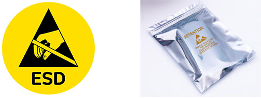
Electrostatic Discharge Protection and Handling

All electrostatic-sensitive components are handled in accordance with electrostatic discharge control procedures. The products are hermetically sealed in anti-static safe packaging to prevent electrostatic damage. Appropriate labeling is also applied for identification and traceability. This ensures product integrity during storage, handling and transportation.


ESD

Certifications & Memberships

Third-party certified, strict quality control. Our certification
  • ISO 9001: 2015
  • ISO 13485: 2016
  • ISO 14001: 2015
  • ISO 28000: 2007
  • ISO 45001: 2018
  • GB/T 27922-2011
  • SMTA
  • IPC
  • ESD
  • PSMA
SS-01GL2-ET Image

SS-01GL2-ET

Omron Electronics Inc-EMC Div
98D-SS-01GL2-ET

Want a better price? Add to Cart and Submit RFQ now, we'll contact you immediately.

0 RFQ
Shopping cart (0 Items)
It is empty.
Compare List (0 Items)
It is empty.
Feedback

Your feedback matters! At Allelco, we value the user experience and strive to improve it constantly.
Please share your comments with us via our feedback form, and we'll respond promptly.
Thank you for choosing Allelco.

Subject
E-mail
Comments
Captcha
Drag or click to upload file
Upload File
types: .xls, .xlsx, .doc, .docx, .jpg, .png and .pdf.
Max file size: 10MB