View All

Please refer to the English Version as our Official Version.Return

Europe
France(Français) Germany(Deutsch) Italy(Italia) Russian(русский) Poland(polski) Czech(Čeština) Luxembourg(Lëtzebuergesch) Netherlands(Nederland) Iceland(íslenska) Hungarian(Magyarország) Spain(español) Portugal(Português) Turkey(Türk dili) Bulgaria(Български език) Ukraine(Україна) Greece(Ελλάδα) Israel(עִבְרִית) Sweden(Svenska) Finland(Svenska) Finland(Suomi) Romania(românesc) Moldova(românesc) Slovakia(Slovenská) Denmark(Dansk) Slovenia(Slovenija) Slovenia(Hrvatska) Croatia(Hrvatska) Serbia(Hrvatska) Montenegro(Hrvatska) Bosnia and Herzegovina(Hrvatska) Lithuania(lietuvių) Spain(Português) Switzerland(Deutsch) United Kingdom(English)
Asia/Pacific
Japan(日本語) Korea(한국의) Thailand(ภาษาไทย) Malaysia(Melayu) Singapore(Melayu) Vietnam(Tiếng Việt) Philippines(Pilipino)
Africa, India and Middle East
United Arab Emirates(العربية) Iran(فارسی) Tajikistan(فارسی) India(हिंदी) Madagascar(malaɡasʲ)
South America / Oceania
New Zealand(Maori) Brazil(Português) Angola(Português) Mozambique(Português)
North America
United States(English) Canada(English) Haiti(Ayiti) Mexico(español)
HomeProductsIntegrated Circuits (ICs)Data Acquisition - Digital PotentiometersX9258TS24-2.7
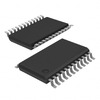
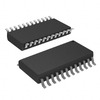
X9258TS24-2.7 Image
Image may be representation.
See specifications for product details.
EXPRESS OPTION
Payment method

X9258TS24-2.7 - Renesas Electronics America Inc

Manufacturer Part Number
X9258TS24-2.7
Manufacturer
Renesas Electronics Corporation
Allelco Part Number
32D-X9258TS24-2.7
Warranty
1 Year Allelco Warranty - Find out more
Stock Status:
5,360 pcs available, New & Original
Parts Description
IC DGT POT 100KOHM 256TAP 24SOIC
Package
24-SOIC
Data sheet
-
RoHs Status
 
Our certification
In stock: 5360

Required fields are indicated by an asterisk (*)
Please send RFQ, we will respond immediately.

Quantity

Specifications

X9258TS24-2.7 Tech Specifications
Renesas Electronics America Inc - X9258TS24-2.7 technical specifications, attributes, parameters and parts with similar specifications to Renesas Electronics America Inc - X9258TS24-2.7

Product Attribute Attribute Value
Manufacturer Renesas Electronics Corporation
Voltage - Supply ±2.7V ~ 5.5V
Tolerance ±20%
Temperature Coefficient (Typ) ±300ppm/°C
Taper Linear
Supplier Device Package 24-SOIC
Series XDCP™
Resistance - Wiper (Ohms) (Typ) 150
Resistance (Ohms) 100k
Package / Case 24-SOIC (0.295', 7.50mm Width)
Product Attribute Attribute Value
Package Tube
Operating Temperature 0°C ~ 70°C
Number of Taps 256
Number of Circuits 4
Mounting Type Surface Mount
Memory Type Non-Volatile
Interface I²C
Features Selectable Address
Configuration Potentiometer
Base Product Number X9258

Environmental & Export Classifications

ATTRIBUTE DESCRIPTION
RoHs Status RoHS non-compliant
Moisture Sensitivity Level (MSL) 5 (48 Hours)
REACH Status REACH Unaffected
ECCN EAR99
HTSUS 8542.39.0001

Parts Introduction

X9258TS24-2.7 Image
X9258TS24-2.7 (1)

Manufacturer Part Number

X9258TS24-2.7

Manufacturer

renesas-electronics-america

Introduction

The X9258TS24-2.7 is a 4-channel, 256-tap, 100kΩ digital potentiometer with an I2C interface and non-volatile memory. It offers a linear taper and features selectable addressing, allowing for easy integration into various applications.

Product Features and Performance

4 independent digital potentiometer channels

256 taps per channel

100kΩ resistance per channel

Linear taper

I2C interface

Non-volatile memory

Selectable address

±2.7V to 5.5V supply voltage

±20% resistance tolerance

±300ppm/°C temperature coefficient

0°C to 70°C operating temperature range

150Ω typical wiper resistance

Product Advantages

Compact 24-SOIC surface mount package

Versatile multi-channel design

Non-volatile memory for retaining settings

Selectable addressing simplifies system integration

Wide operating voltage range

Key Reasons to Choose This Product

Precise digital control of resistance values

Reliable non-volatile memory for maintaining settings

Flexibility in system design with multi-channel and selectable addressing features

Cost-effective solution for applications requiring programmable resistance

Quality and Safety Features

RoHS-compliant

Recognized under the UL Component Recognition Program

Compatibility

This digital potentiometer is compatible with various microcontrollers and systems that support the I2C communication protocol.

Application Areas

Audio equipment

Instrumentation and test equipment

Industrial control systems

Consumer electronics

Medical devices

Product Lifecycle

The X9258TS24-2.7 is an obsolete product. Customers are advised to contact our website's sales team for information on equivalent or alternative models that may be available.
Frequently Asked Questions(FAQ)

What are the key differences between the X9258TS24-2.7 and alternative models like the X9258TS24Z-2.7 in terms of pin configuration and electrical characteristics?
The X9258TS24-2.7 and X9258TS24Z-2.7 share the same core functionality as 4-circuit digital potentiometers with 256 taps and 100kΩ nominal resistance, but differ primarily in their package marking and possibly manufacturing traceability. Both utilize a 24-SOIC package (7.50mm width) and operate over a ±2.7V to 5.5V supply range with identical I²C interface protocols. However, the "-2.7" variant typically indicates a specific voltage rating or revision, while "Z-2.7" may denote a different packaging lot or RoHS compliance path. Engineers should verify absolute maximum ratings and thermal derating curves when substituting between these part numbers due to potential variations in internal layout affecting power dissipation under continuous wiper operation.
How does the ±20% tolerance of the X9258TS24-2.7 impact system calibration accuracy in precision analog signal conditioning applications?
In closed-loop systems where the X9258TS24-2.7 is used for gain adjustment or offset trimming, its ±20% resistor element tolerance introduces significant uncertainty in the final output voltage. For example, in a non-inverting amplifier configuration with R1 = 10kΩ and Rf set by the wiper position, a worst-case mismatch could result in actual gains varying up to ±25% depending on tap selection. This limits the device’s suitability for high-accuracy applications such as medical instrumentation or precision data acquisition without additional calibration routines or post-trim compensation techniques.
Can the X9258TS24-2.7 be safely operated near its supply voltage limits, particularly when driving capacitive loads or in low-impedance feedback paths?
Operating the X9258TS24-2.7 near its minimum supply voltage (e.g., 2.7V) reduces headroom for output swing in analog front-end designs, potentially causing distortion if the wiper attempts to source current into capacitive loads. Additionally, during dynamic tap transitions, transient currents can momentarily exceed internal protection thresholds. While the device includes basic ESD protection, designers must ensure that total power dissipation remains below the SOIC-24 junction-to-ambient limit—typically 500mW at 70°C—by limiting wiper current to <1mA and avoiding sustained short-circuit conditions across terminals A and B.
Why might an engineer choose the X9258TS24-2.7 over single-channel alternatives despite its higher channel count?
Although the X9258TS24-2.7 integrates four independent potentiometer circuits, it offers architectural advantages in cost-sensitive, multi-parameter tuning applications such as sensor linearization or bias point adjustment across multiple stages. By sharing an I²C bus and control logic, it reduces board space and component count compared to discrete solutions. However, this benefit only applies when all channels require coordinated tuning; otherwise, simpler single-pot configurations may offer better resolution per channel or lower quiescent power consumption.
What precautions should be taken when cascading multiple instances of the X9258TS24-2.7 on the same I²C bus?
When connecting multiple X9258TS24-2.7 devices via I²C, each must have a unique address configured through its A0–A2 pins to prevent bus contention. Given the standard I²C clock frequency (up to 400kHz), propagation delays from multiple slaves can degrade signal integrity, especially over long traces. Designers should include pull-up resistors matched to bus capacitance (typically 1–10kΩ for ≤400pF) and consider adding series termination near drivers to mitigate reflections. Additionally, simultaneous writes to different addresses must account for arbitration timing to avoid unintended state changes.
How does the temperature coefficient (±300ppm/°C) of the X9258TS24-2.7 affect long-term stability in industrial environments?
Over a 50°C operating span (e.g., 0°C to 50°C), the X9258TS24-2.7’s resistance variation due to temperature can reach ±15Ω from the nominal 100kΩ value, equivalent to a ±0.015% shift. While this may seem negligible, repeated cycling or exposure to thermal gradients can exacerbate drift beyond datasheet specifications. In thermally unstable environments, external reference voltages or software-based drift compensation algorithms become necessary to maintain system-level accuracy within required tolerances.
Is the X9258TS24-2.7 suitable for use in battery-powered systems requiring ultra-low standby current?
No, the X9258TS24-2.7 is not optimized for ultra-low-power applications. With typical quiescent current around 150μA at 5V supply and active mode draw exceeding 1mA during write cycles, it consumes significantly more power than modern low-power digital pots or analog alternatives. For battery-operated devices, alternative architectures using switched-capacitor techniques or external FET-based variable resistors with microcontroller control would yield superior energy efficiency while maintaining programmability.
What are the implications of the RoHS non-compliance status for the X9258TS24-2.7 in regulated markets?
The RoHS non-compliance of the X9258TS24-2.7 restricts its use in regions mandating strict restriction of hazardous substances, such as the European Union. Substitution with compliant variants—like the X9258TS24Z-2.7, which may meet RoHS standards—is often required for end-product certification. Manufacturers must also evaluate lead-free soldering compatibility, as certain lead-containing alloys exhibit different wetting behaviors during reflow, potentially affecting solder joint reliability under thermal stress.
How does the wiper resistance (150Ω typ.) of the X9258TS24-2.7 influence high-impedance circuit performance?
At 150Ω wiper resistance, the X9258TS24-2.7 introduces a fixed loss when used in high-impedance voltage divider configurations, such as sensor interfaces or reference buffer outputs. For instance, in a 1MΩ divider network, this adds a 0.15% static error; however, in lower-impedance contexts (e.g., <10kΩ), the impact becomes negligible. Designers should avoid using the wiper as a direct load driver without buffering, as loading effects could distort small-signal measurements or reduce output drive capability.
What design considerations apply when replacing legacy analog potentiometers with the X9258TS24-2.7 in existing PCBs?
Replacing mechanical pots with the X9258TS24-2.7 requires careful attention to control signal routing, as I²C lines demand proper pull-ups and limited stub lengths to preserve rise times. Additionally, the digital nature of the device introduces quantization steps (100kΩ / 256 ≈ 390Ω per step), which may necessitate oversampling or dithering in audio or precision control loops to mask discrete stepping artifacts. Layout symmetry around the SOIC package is also critical to minimize crosstalk between adjacent resistor strings.
How do the non-volatile memory features of the X9258TS24-2.7 compare to volatile counterparts in terms of system boot behavior?
Unlike volatile digital pots that lose settings upon power-down, the X9258TS24-2.7 retains wiper positions across power cycles, eliminating the need for re-initialization code during startup. This simplifies firmware design but introduces risk if incorrect default states persist after unexpected brownouts. System integrators should implement watchdog-reset-safe initialization sequences to override any erroneous stored values until verified against safe operating conditions.
Can the X9258TS24-2.7 directly replace Bourns or Analog Devices digital potentiometers in mixed-signal PCB layouts?
Direct replacement depends on matching pinout, package footprint, and electrical interface compatibility. While the X9258TS24-2.7 uses a standard 24-pin SOIC layout, differences in command protocols or tap linearity may disrupt existing firmware. Moreover, impedance matching and grounding schemes optimized for competing devices may not translate cleanly. Full validation including transient response and EMI characteristics is recommended before committing to substitution in production designs.
What role does the MSL 5 designation play in handling and storage of the X9258TS24-2.7 prior to assembly?
As an MSL 5 component, the X9258TS24-2.7 has a floor life of 48 hours at 30°C/60% RH before requiring bake-out to remove absorbed moisture. Extended exposure beyond this window risks delamination during reflow, leading to popcorning failures. Assembly facilities must track time-to-oven using sealed containers with desiccant indicators and adhere to JEDEC J-STD-033 guidelines for humidity preconditioning.
How does the selectable address feature of the X9258TS24-2.7 enable flexible system integration in multi-drop I²C topologies?
The X9258TS24-2.7 supports three hardware-selectable addresses via its A0–A2 pins, allowing up to eight devices on a single I²C bus without address conflicts. This facilitates modular subsystem designs where multiple tuning functions (e.g., gain, offset, filter cutoff) are distributed across boards. However, each address combination must be validated against internal register maps to ensure no unintended side effects occur during concurrent access attempts.
Are there any known limitations in the linearity or DNL/INL characteristics of the X9258TS24-2.7 that affect precision DAC emulation?
Yes, the X9258TS24-2.7 exhibits non-linear transfer characteristics typical of segmented resistive ladders rather than ideal binary-weighted networks. Differential Non-Linearity (DNL) can reach ±2 LSB under worst-case process corners, making it unsuitable for direct ADC/DAC replacement in high-resolution conversion chains. Its primary utility lies in coarse analog adjustments rather than fine digital-to-analog translation tasks requiring monotonicity and sub-LSB precision.

Parts with Similar Specifications

The three parts on the right have similar specifications to Renesas Electronics America Inc X9258TS24-2.7

Product Attribute X9258TS24I-2.7T1 X9258TS24I-2.7 X9258TS24-2.7 X9258TS24-2.7T1
Part Number X9258TS24I-2.7T1 X9258TS24I-2.7 X9258TS24-2.7 X9258TS24-2.7T1
Manufacturer Renesas Electronics America Inc Renesas Electronics America Inc Intersil Renesas Electronics America Inc
Resistance (Ohms) - - - -
Resistance - Wiper (Ohms) (Typ) - - - -
Package - Tape & Reel (TR) Tube Tape & Reel (TR)
Memory Type - - - -
Features - - - Simultaneous Sampling
Tolerance - - - -
Configuration - - - S/H-ADC
Base Product Number - DAC34H84 MAX500 ADS62P42
Number of Taps - - - -
Interface - - - -
Package / Case - 196-LFBGA 16-DIP (0.300', 7.62mm) 64-VFQFN Exposed Pad
Taper - - - -
Mounting Type - Surface Mount Through Hole Surface Mount
Series - - - -
Operating Temperature - -40°C ~ 85°C 0°C ~ 70°C -40°C ~ 85°C
Number of Circuits - - - -
Supplier Device Package - 196-NFBGA (12x12) 16-PDIP 64-VQFN (9x9)
Temperature Coefficient (Typ) - - - -
Voltage - Supply - - - -

Customer Reviews

Evaluation: 10 Articles

  • ECUb***h
    Sep 22, 2026

    Used for repair of an older automotive ECU. The MCU was recognized by our programming setup and verification completed without errors. The repaired board now starts and communicates normally.

  • RS48***ieldTech
    Sep 16, 2026

    Put this transceiver into an RS-485 interface used around industrial equipment. Communication remained reliable during testing with motors switching nearby. Good result for the replacement board.

  • Logi***b_Chris
    Sep 8, 2026

    Purchased for a Cyclone III development project. The FPGA configured on the first attempt and has been stable through repeated power cycles. No problems with the I/O we are using.

  • Circ***FixerTom
    Sep 2, 2026

    Used this rectifier in a high-current power supply repair. Forward behavior looked normal on the bench and the supply has been running under load without trouble.

  • Retr***UWorks
    Aug 31, 2026

    Needed the exact ST10F269Z2Q6 for servicing an older control unit. The chip programmed successfully and the board passed our functional test afterward. Much easier than redesigning around a newer MCU.

  • Andr***PCBLab
    Aug 28, 2026

    I needed this ADC for an older data acquisition board. Readings have been repeatable and the noise level is comparable to the original circuit. Happy with the purchase.

  • Leat***O'Keefe
    Aug 20, 2026

    one of my hobbies is skydiving. and when i'm skydiving this works great.

  • Ilen***
    Aug 20, 2026

    This product works considerably well. It secretly improves my basketball by a lot.

  • Indu***ialPower
    Aug 17, 2026

    Installed this IGBT module in a power conversion cabinet. Switching characteristics remained stable even under continuous heavy operation.

  • Nikh***ech
    Aug 13, 2026

    Great low-power MCU for portable equipment. Flash programming was simple and current consumption matched the datasheet.

Write a Review

Your Email address will not be published.

Shipment

Delivery Time

In-stock items can be shipped within 24 hours. Some parts will be arranged for delivery within 1-2 days from the date all items arrive at our warehouse. And Allelco ships order once a day at about 17:00, except Sunday. Once the goods are shipped, the estimated delivery time depends on the shipping methods and Delivery destination. The table below shows are the logistic time for some common countries.

Delivery Cost

  1. Use your express account for shipment if you have one.
  2. Use our account for the shipment. Refer to the table below for the approximate charges.
(Different time frame / countries / package size has different price.)

Delivery Method

  1. Global Common Shipment by DHL / UPS / FedEx / TNT / EMS / SF we support.
  2. Others more shipping ways, please get in touch with your customer manager.

Common Countries Logistic Time Reference
Region Country Logistic Time(Day)
America United States 5
Brazil 7
Europe Germany 5
United Kingdom 4
Italy 5
Oceania Australia 6
New Zealand 5
Asia India 4
Japan 4
Middle East Israel 6
DHL & FedEx Shipment Charges Reference
Shipment charges(KG) Reference DHL(USD$)
0.00kg-1.00kg USD$30.00 - USD$60.00
1.00kg-2.00kg USD$40.00 - USD$80.00
2.00kg-3.00kg USD$50.00 - USD$100.00
Note:
The above table is for reference only. There may have some data bias for the uncontrollable factors.
Contact us if you have any questions.
  • QC (Quality Warranty)
  • Payment Support
  • Packaging
  • Certifications & Memberships

QC (Quality Warranty)

Allelco is committed to exceeding customer expectations through customer service excellence, order accuracy, and on-time delivery.
This is achieved through our commitment to the continual improvement of our processes, services, and products.


Strict quality inspection builds a solid foundation for electronic component quality.
  1. Visual inspection
  2. Performance testing and reliability verification
  3. Standardized full-process testing
  4. Precise control of every parameter
We eliminate defective components and ensure the stable operation of electronic devices through professional quality standards.

Payment Support

The payment method can be chosen from the methods shown below: Wire Transfer (T/T, Bank Transfer), Western Union, Credit card, PayPal.
  • HKBea
  • Paypal
  • MasterCard
  • Western-Union
  • VISA
Stable Delivery, Sincere Partnership — Your Faithful Supply Chain Partner
  • Efficient Supply Management
  • Cost-Saving Procurement
  • Fast Sourcing & Delivery
Contact us if you have any questions.

Packaging

Electrostatic Discharge Protection and Handling

All electrostatic-sensitive components are handled in accordance with electrostatic discharge control procedures. The products are hermetically sealed in anti-static safe packaging to prevent electrostatic damage. Appropriate labeling is also applied for identification and traceability. This ensures product integrity during storage, handling and transportation.


ESD

Certifications & Memberships

Third-party certified, strict quality control. Our certification
  • ISO 9001: 2015
  • ISO 13485: 2016
  • ISO 14001: 2015
  • ISO 28000: 2007
  • ISO 45001: 2018
  • GB/T 27922-2011
  • SMTA
  • IPC
  • ESD
  • PSMA
X9258TS24-2.7 Image

X9258TS24-2.7

Renesas Electronics America Inc
32D-X9258TS24-2.7

Want a better price? Add to Cart and Submit RFQ now, we'll contact you immediately.

0 RFQ
Shopping cart (0 Items)
It is empty.
Compare List (0 Items)
It is empty.
Feedback

Your feedback matters! At Allelco, we value the user experience and strive to improve it constantly.
Please share your comments with us via our feedback form, and we'll respond promptly.
Thank you for choosing Allelco.

Subject
E-mail
Comments
Captcha
Drag or click to upload file
Upload File
types: .xls, .xlsx, .doc, .docx, .jpg, .png and .pdf.
Max file size: 10MB