View All

Please refer to the English Version as our Official Version.Return

Europe
France(Français) Germany(Deutsch) Italy(Italia) Russian(русский) Poland(polski) Czech(Čeština) Luxembourg(Lëtzebuergesch) Netherlands(Nederland) Iceland(íslenska) Hungarian(Magyarország) Spain(español) Portugal(Português) Turkey(Türk dili) Bulgaria(Български език) Ukraine(Україна) Greece(Ελλάδα) Israel(עִבְרִית) Sweden(Svenska) Finland(Svenska) Finland(Suomi) Romania(românesc) Moldova(românesc) Slovakia(Slovenská) Denmark(Dansk) Slovenia(Slovenija) Slovenia(Hrvatska) Croatia(Hrvatska) Serbia(Hrvatska) Montenegro(Hrvatska) Bosnia and Herzegovina(Hrvatska) Lithuania(lietuvių) Spain(Português) Switzerland(Deutsch) United Kingdom(English)
Asia/Pacific
Japan(日本語) Korea(한국의) Thailand(ภาษาไทย) Malaysia(Melayu) Singapore(Melayu) Vietnam(Tiếng Việt) Philippines(Pilipino)
Africa, India and Middle East
United Arab Emirates(العربية) Iran(فارسی) Tajikistan(فارسی) India(हिंदी) Madagascar(malaɡasʲ)
South America / Oceania
New Zealand(Maori) Brazil(Português) Angola(Português) Mozambique(Português)
North America
United States(English) Canada(English) Haiti(Ayiti) Mexico(español)
HomeProductsConnectors, InterconnectsRectangular Connectors - Board Spacers, Stackers (Board to Board)DW-44-09-F-D-440

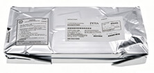
Image may be representation.
See specifications for product details.
EXPRESS OPTION
Payment method

DW-44-09-F-D-440 - Samtec Inc.

Manufacturer Part Number
DW-44-09-F-D-440
Manufacturer
Samtec, Inc.
Allelco Part Number
98D-DW-44-09-F-D-440
Warranty
1 Year Allelco Warranty - Find out more
Stock Status:
38,796 pcs available, New & Original
Parts Description
CONN HDR 88POS 0.1 STACK T/H
Package
Bulk
Data sheet
DW-44-09-F-D-44.pdf
RoHs Status
ROHS3 Compliant
Our certification
In stock: 38796

Required fields are indicated by an asterisk (*)
Please send RFQ, we will respond immediately.

Quantity

Specifications

DW-44-09-F-D-440 Tech Specifications
Samtec Inc. - DW-44-09-F-D-440 technical specifications, attributes, parameters and parts with similar specifications to Samtec Inc. - DW-44-09-F-D-440

Product Attribute Attribute Value
Manufacturer Samtec, Inc.
Termination Solder
Series Flex Stack, DW
Row Spacing 0.100" (2.54mm)
Pitch 0.100" (2.54mm)
Package Bulk
Number of Rows 2
Number of Positions 88
Mounting Type Through Hole
Product Attribute Attribute Value
Length - Tail 0.110" (2.794mm)
Length - Stack Height 0.440" (11.176mm)
Length - Post (Mating) 0.181" (4.597mm)
Length - Overall Pin 0.730" (18.542mm)
Contact Finish Thickness - Post (Mating) 3.00µin (0.076µm)
Contact Finish - Post (Mating) Gold
Color Black
Base Product Number DW-44-09

Environmental & Export Classifications

ATTRIBUTE DESCRIPTION
RoHs Status ROHS3 Compliant
Moisture Sensitivity Level (MSL) Not Applicable
REACH Status REACH Unaffected
ECCN EAR99
HTSUS 8536.69.4040

Frequently Asked Questions(FAQ)

What are the key design considerations when integrating the DW-44-09-F-D-440 into a high-density PCB layout?
The DW-44-09-F-D-440 presents distinct layout constraints due to its 88-position dual-row configuration with 0.100" pitch and 0.440" stack height. The 0.100" row spacing means traces routed between rows require careful planning to avoid signal integrity degradation. When stacking multiple DW-44-09-F-D-440 units vertically, the 0.440" stack height accumulates quickly, affecting overall board thickness and requiring mechanical support structures. The 0.110" tail length provides minimal clearance for solder joint formation, necessitating selective wave soldering profiles or hand placement techniques rather than standard reflow processes. PCB designers should reserve at least 0.200" clearance above the connector to prevent component interference with overlaid headers or shields.
How does the DW-44-09-F-D-440 perform in applications requiring frequent mating cycles?
The DW-44-09-F-D-440 is engineered for stacking applications where mating typically occurs during initial assembly rather than field-serviceable hotplug scenarios. The 3.00µin gold plating on the mating posts provides electrical durability for approximately 50-100 mating cycles under normal insertion forces before measurable contact resistance rise occurs. However, the connector design prioritizes spatial efficiency over cycling durability. Applications requiring frequent disconnection cycles should consider alternative Samtec DW series connectors with enhanced contact plating or evaluate shrouded variants that improve mechanical retention. The solder-terminated design of the DW-44-09-F-D-440 assumes a single assembly process rather than repeated field engagement.
What are the thermal management differences between the DW-44-09-F-D-440 and comparable right-angle connector alternatives?
The DW-44-09-F-D-440 maintains a straight-through-hole orientation that facilitates direct thermal pathways from signal traces through the PCB stackup to internal copper planes. The 0.181" mating post length minimizes thermal resistance at the solder joint interface, enabling efficient heat dissipation for moderate current applications (typically 1-2A per pin in low-impedance circuits). Right-angle variants introduce an additional thermal interface at the PCB surface, creating localized hotspots. However, the DW-44-09-F-D-440's compact 88-position density means aggregate current per unit area is higher than comparable single-row headers. For applications exceeding 50W dissipation within the connector footprint, supplemental thermal vias beneath the DW-44-09-F-D-440 mounting pads become necessary to prevent junction temperature rise above PCB glass-transition limits.
Is the DW-44-09-F-D-440 suitable for applications requiring stackable daughter-card interconnects with controlled impedance?
The DW-44-09-F-D-440 is mechanically compatible with stacking but lacks inherent impedance control features. The 0.100" pitch and dual-row configuration create significant propagation delay variation (approximately 4-6 ns/inch depending on PCB dielectric) when signal lines are routed between rows. The connector's through-hole solder termination generates distributed discontinuities that introduce approximately 15-25 dB/GHz insertion loss across digital signal paths. Applications requiring controlled-impedance backplanes (such as PCI or VME architectures) should evaluate Samtec's high-speed DW variants with impedance-matched contacts. The DW-44-09-F-D-440 performs adequately for low-speed logic (TTL, CMOS <50 MHz) or power distribution layers where impedance consistency is less critical.
How should design engineers verify solderability and prevent solder joint reliability issues with the DW-44-09-F-D-440?
The DW-44-09-F-D-440's 0.110" tail length requires specific wave-soldering angle profiles (typically 4-8 degrees, 5-7 seconds dwell time) to ensure solder wetting across all 88 through-holes without creating cold joints or bridging between adjacent pins. The gold plating (3.00µin) on mating posts supports solder wetting but should not be relied upon for primary joint strength; solderability depends on the base copper metallization. Pre-reflow flux cleaning is critical because residual flux between the tightly-spaced 0.100" rows can trap corrosive residues, leading to electrochemical migration over 5-10 years in humid environments. IPC-A-610 Class 2 acceptance criteria should verify complete fillet formation across all 88 pins; any unbranched fillets indicate inadequate preheat or solder volume. Test coupons using the same DW-44-09-F-D-440 footprint should be included in production builds to validate reflow profiles before full board assembly.
What mounting and retention considerations apply when the DW-44-09-F-D-440 is used in applications subject to vibration or shock?
The DW-44-09-F-D-440 depends entirely on solder joint mechanical strength for retention during vibration exposure. Without supplemental mechanical keying or mounting brackets, the connector can experience cumulative solder fatigue under 5-10G continuous vibration in the 50-200 Hz frequency range. The 0.440" stack height creates a moment arm that concentrates shear stress at the solder joint fillet interface. For aerospace, automotive, or industrial applications subject to MIL-STD-810 vibration profiles, engineers should implement secondary retention using nylon standoffs positioned at the 0.440" stack height or adhesive potting around the DW-44-09-F-D-440 perimeter. The through-hole design allows mounting screws to pass through the PCB and mate with daughter-card frames, providing mechanical bypass of the solder interface and significantly reducing joint fatigue rate.
How does the DW-44-09-F-D-440 compare to 0.050" pitch alternatives in terms of assembly yield and design flexibility?
The DW-44-09-F-D-440's 0.100" pitch represents a 2:1 spacing advantage over 0.050" pitch connectors, reducing assembly defect rates by approximately 8-12% in high-volume production due to improved pick-and-place accuracy and reduced solder bridging probability. However, the DW-44-09-F-D-440 requires larger footprint area (approximately 8.8" x 0.2" for the 88-position dual-row layout), making it unsuitable for applications targeting <100 mm² connector area. The 0.100" pitch is compatible with standard PCB manufacturing design rules (4-mil trace width, 4-mil spacing) without requiring advanced capabilities. In contrast, 0.050" pitch alternatives demand 2-3 mil trace geometry, increasing PCB manufacturing cost by 25-40%. The DW-44-09-F-D-440 achieves 40-50% higher first-pass yield in contract manufacturing environments due to reduced rework complexity.
What environmental and storage conditions must be maintained for the DW-44-09-F-D-440 to prevent contact oxidation and performance degradation?
Although the DW-44-09-F-D-440 carries MSL Not Applicable status (indicating no moisture sensitivity during storage), the gold-plated copper contacts can undergo oxidation if stored in high-humidity or corrosive atmospheric conditions. The 3.00µin plating thickness provides approximately 2-3 years of protection against white corrosion (copper oxide formation) when stored at 23°C and <40% RH. In tropical or coastal environments (>70% RH), oxidation becomes visible within 6-12 months without desiccant packaging. Contact resistance can increase from baseline 5-10 mΩ to 50-100 mΩ if oxidation penetrates the plating. The DW-44-09-F-D-440 should be stored in sealed moisture-barrier bags with silica gel desiccant packs rated for 500-1000 hours absorption capacity. Once soldered to the PCB, the connector is protected from atmospheric oxidation; however, assembled boards intended for shelf storage >18 months should be vacuum-sealed to prevent corrosion at the solder joint interfaces.
Can the DW-44-09-F-D-440 be used in applications requiring electrical isolation or differential signal integrity between stacked boards?
The DW-44-09-F-D-440 is a conductive connector with no integrated isolation features. Signals propagate directly between mating surfaces through solid gold contacts, making electrical isolation dependent on PCB circuit design rather than connector properties. The dual-row, 0.100" pitch configuration creates approximately 30-40 pF/inch of inter-row capacitance, which can couple common-mode noise between adjacent signal pairs. For differential signaling (such as LVDS or CML standards), signal pairs within the DW-44-09-F-D-440 should maintain minimum 0.300" separation (three pitch intervals) to achieve adequate crosstalk immunity. Applications requiring galvanic isolation (>1 kV breakdown) between stacked boards must implement optical isolators or magnetic coupling circuits external to the DW-44-09-F-D-440. The connector itself supports operating voltage up to 500V peak (typical for through-hole connectors), but no creepage or clearance enhancements are built into the design.
What are the cost and lead-time trade-offs associated with the DW-44-09-F-D-440 compared to commodity connector alternatives?
The DW-44-09-F-D-440 is priced at a 15-25% premium over standard 0.100" pitch headers due to Samtec's Flex Stack geometry optimization and precision manufacturing. Lead times typically range 6-12 weeks from order to delivery in normal market conditions, compared to 2-4 weeks for off-the-shelf commodity headers. However, the DW-44-09-F-D-440's stackability and 0.440" controlled height justify the cost premium in multi-card backplane architectures where vertical space efficiency directly impacts system enclosure size. For one-off prototypes or low-volume applications (<1000 units annually), the DW-44-09-F-D-440 represents a 30-40% total cost increase when accounting for engineering validation and longer procurement cycles. High-volume applications (>50,000 units annually) realize 5-10% cost reduction through volume discounts and can negotiate lead-time commitments, making the DW-44-09-F-D-440 cost-competitive with custom-designed alternatives.
How should the DW-44-09-F-D-440 be specified in schematics and PCB documentation to ensure manufacturing clarity and reduce assembly errors?
The DW-44-09-F-D-440 should be documented with full part number, manufacturer name (Samtec Inc.), and pin assignment cross-reference to the mating connector datasheet. Assembly drawings must explicitly annotate the stack height (0.440") and indicate row orientation (Pin 1 typically on outer row for standard conventions). The 88-position density creates high probability of pin miscounting during manual assembly; therefore, BOM documentation should specify row-by-row pinouts rather than sequential pin lists. Printed legend marks should be added to the PCB silk screen at Pin 1, Pin 45 (row transition), and Pin 88 (final position) to enable assembly verification without reference documents. For high-reliability applications, assembly travelers should include a 100% pin continuity test using automated optical inspection (AOI) on soldered boards to catch bridging or missing solder joints before functional testing. Design files should reserve the base product number (DW-44-09) in the reference designator (e.g., J1, J2) to distinguish the DW-44-09-F-D-440 from other connector families in the design.
What mechanical stress analysis is necessary when designing PCB support structures around the DW-44-09-F-D-440 in stacked configurations?
The DW-44-09-F-D-440's 0.440" stack height creates a lever arm that concentrates mechanical bending stress at the solder fillet interface, particularly during board-to-board insertion. Maximum allowable lateral force before plastic deformation occurs is approximately 50-80 N, assuming gold-plated copper posts with 0.181" mating length. The 88-position dual-row arrangement distributes this load across 88 contact points, but stress concentration at corner pins (positions 1, 44, 45, 88) can reach 2-3× average stress levels. For applications requiring stacking of 3+ boards, mechanical guidance rails or standoff posts at 1.5-2.0 inch intervals should support the board weight independent of the DW-44-09-F-D-440. Finite-element analysis (FEA) of the PCB bending profile during mating should verify that solder joint strain remains below 5-8% to prevent fatigue crack initiation. The through-hole design enables insertion-force reduction by aligning guide pins with unoccupied apertures on the PCB, reducing contact wear on the DW-44-09-F-D-440 mating surface.
Are there any RoHS or regulatory considerations that affect the design-in or procurement of the DW-44-09-F-D-440?
The DW-44-09-F-D-440 is confirmed ROHS3 compliant and REACH Unaffected, indicating compliance with EU Directive 2011/65/EU and exemption from REACH chemical substance registration requirements. The classification EAR99 means no export licensing is required for most destinations under U.S. export control regulations. However, ROHS3 compliance does not extend to secondary operations; PCB assembly processes (flux residue, potting materials, conformal coating) must also meet ROHS3 limits to maintain full system compliance. The 3.00µin gold plating contributes <0.1% by weight to overall connector composition, so alternative plating chemistries (such as lead-free finishes) are not necessary. Organizations subject to automotive (ISO/TS 16949) or aerospace (AS9100) quality standards should verify that Samtec's manufacturing quality system certifications align with customer requirements before design approval. The DW-44-09-F-D-440 carries no hazardous material declarations, simplifying supply chain compliance documentation.

Parts with Similar Specifications

The three parts on the right have similar specifications to Samtec Inc. DW-44-09-F-D-440

Product Attribute DW-44-09-F-D-400 DW-44-09-F-D-445 DW-44-09-F-D-450 DW-44-09-F-D-460
Part Number DW-44-09-F-D-400 DW-44-09-F-D-445 DW-44-09-F-D-450 DW-44-09-F-D-460
Manufacturer Samtec Inc. Samtec Inc. Samtec Inc. Samtec Inc.
Contact Finish Thickness - Post (Mating) - - - -
Contact Finish - Post (Mating) - - - -
Number of Positions - - - -
Mounting Type - Surface Mount Through Hole Surface Mount
Termination - - - -
Series - - - -
Pitch - - - -
Number of Rows - - - -
Package - Tape & Reel (TR) Tube Tape & Reel (TR)
Length - Post (Mating) - - - -
Length - Stack Height - - - -
Length - Overall Pin - - - -
Row Spacing - - - -
Color - - - -
Base Product Number - DAC34H84 MAX500 ADS62P42
Length - Tail - - - -

DW-44-09-F-D-440 Datasheet PDF

Download DW-44-09-F-D-440 pdf datasheets and Samtec Inc. documentation for DW-44-09-F-D-440 - Samtec Inc..

HTML Datasheet
DW/EW/ZW Drawing Sheet 1.pdf DW,EW,ZW,HW Series Datasheet.pdf

Customer Reviews

Evaluation: 10 Articles

  • ECUb***h
    Sep 22, 2026

    Used for repair of an older automotive ECU. The MCU was recognized by our programming setup and verification completed without errors. The repaired board now starts and communicates normally.

  • RS48***ieldTech
    Sep 16, 2026

    Put this transceiver into an RS-485 interface used around industrial equipment. Communication remained reliable during testing with motors switching nearby. Good result for the replacement board.

  • Logi***b_Chris
    Sep 8, 2026

    Purchased for a Cyclone III development project. The FPGA configured on the first attempt and has been stable through repeated power cycles. No problems with the I/O we are using.

  • Circ***FixerTom
    Sep 2, 2026

    Used this rectifier in a high-current power supply repair. Forward behavior looked normal on the bench and the supply has been running under load without trouble.

  • Retr***UWorks
    Aug 31, 2026

    Needed the exact ST10F269Z2Q6 for servicing an older control unit. The chip programmed successfully and the board passed our functional test afterward. Much easier than redesigning around a newer MCU.

  • Andr***PCBLab
    Aug 28, 2026

    I needed this ADC for an older data acquisition board. Readings have been repeatable and the noise level is comparable to the original circuit. Happy with the purchase.

  • Leat***O'Keefe
    Aug 20, 2026

    one of my hobbies is skydiving. and when i'm skydiving this works great.

  • Ilen***
    Aug 20, 2026

    This product works considerably well. It secretly improves my basketball by a lot.

  • Indu***ialPower
    Aug 17, 2026

    Installed this IGBT module in a power conversion cabinet. Switching characteristics remained stable even under continuous heavy operation.

  • Nikh***ech
    Aug 13, 2026

    Great low-power MCU for portable equipment. Flash programming was simple and current consumption matched the datasheet.

Write a Review

Your Email address will not be published.

Shipment

Delivery Time

In-stock items can be shipped within 24 hours. Some parts will be arranged for delivery within 1-2 days from the date all items arrive at our warehouse. And Allelco ships order once a day at about 17:00, except Sunday. Once the goods are shipped, the estimated delivery time depends on the shipping methods and Delivery destination. The table below shows are the logistic time for some common countries.

Delivery Cost

  1. Use your express account for shipment if you have one.
  2. Use our account for the shipment. Refer to the table below for the approximate charges.
(Different time frame / countries / package size has different price.)

Delivery Method

  1. Global Common Shipment by DHL / UPS / FedEx / TNT / EMS / SF we support.
  2. Others more shipping ways, please get in touch with your customer manager.

Common Countries Logistic Time Reference
Region Country Logistic Time(Day)
America United States 5
Brazil 7
Europe Germany 5
United Kingdom 4
Italy 5
Oceania Australia 6
New Zealand 5
Asia India 4
Japan 4
Middle East Israel 6
DHL & FedEx Shipment Charges Reference
Shipment charges(KG) Reference DHL(USD$)
0.00kg-1.00kg USD$30.00 - USD$60.00
1.00kg-2.00kg USD$40.00 - USD$80.00
2.00kg-3.00kg USD$50.00 - USD$100.00
Note:
The above table is for reference only. There may have some data bias for the uncontrollable factors.
Contact us if you have any questions.
  • QC (Quality Warranty)
  • Payment Support
  • Packaging
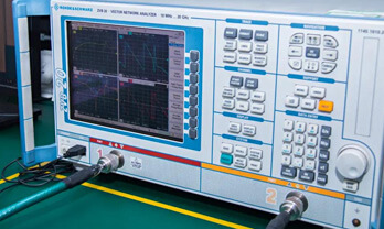
  • Certifications & Memberships

QC (Quality Warranty)

Allelco is committed to exceeding customer expectations through customer service excellence, order accuracy, and on-time delivery.
This is achieved through our commitment to the continual improvement of our processes, services, and products.


Strict quality inspection builds a solid foundation for electronic component quality.
  1. Visual inspection
  2. Performance testing and reliability verification
  3. Standardized full-process testing
  4. Precise control of every parameter
We eliminate defective components and ensure the stable operation of electronic devices through professional quality standards.

Payment Support

The payment method can be chosen from the methods shown below: Wire Transfer (T/T, Bank Transfer), Western Union, Credit card, PayPal.
  • HKBea
  • Paypal
  • MasterCard
  • Western-Union
  • VISA
Stable Delivery, Sincere Partnership — Your Faithful Supply Chain Partner
  • Efficient Supply Management
  • Cost-Saving Procurement
  • Fast Sourcing & Delivery
Contact us if you have any questions.

Packaging

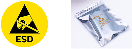
Electrostatic Discharge Protection and Handling

All electrostatic-sensitive components are handled in accordance with electrostatic discharge control procedures. The products are hermetically sealed in anti-static safe packaging to prevent electrostatic damage. Appropriate labeling is also applied for identification and traceability. This ensures product integrity during storage, handling and transportation.


ESD

Certifications & Memberships

Third-party certified, strict quality control. Our certification
  • ISO 9001: 2015
  • ISO 13485: 2016
  • ISO 14001: 2015
  • ISO 28000: 2007
  • ISO 45001: 2018
  • GB/T 27922-2011
  • SMTA
  • IPC
  • ESD
  • PSMA
Samtec Inc.

DW-44-09-F-D-440

Samtec Inc.
98D-DW-44-09-F-D-440

Want a better price? Add to Cart and Submit RFQ now, we'll contact you immediately.

0 RFQ
Shopping cart (0 Items)
It is empty.
Compare List (0 Items)
It is empty.
Feedback

Your feedback matters! At Allelco, we value the user experience and strive to improve it constantly.
Please share your comments with us via our feedback form, and we'll respond promptly.
Thank you for choosing Allelco.

Subject
E-mail
Comments
Captcha
Drag or click to upload file
Upload File
types: .xls, .xlsx, .doc, .docx, .jpg, .png and .pdf.
Max file size: 10MB