View All

Please refer to the English Version as our Official Version.Return

Europe
France(Français) Germany(Deutsch) Italy(Italia) Russian(русский) Poland(polski) Czech(Čeština) Luxembourg(Lëtzebuergesch) Netherlands(Nederland) Iceland(íslenska) Hungarian(Magyarország) Spain(español) Portugal(Português) Turkey(Türk dili) Bulgaria(Български език) Ukraine(Україна) Greece(Ελλάδα) Israel(עִבְרִית) Sweden(Svenska) Finland(Svenska) Finland(Suomi) Romania(românesc) Moldova(românesc) Slovakia(Slovenská) Denmark(Dansk) Slovenia(Slovenija) Slovenia(Hrvatska) Croatia(Hrvatska) Serbia(Hrvatska) Montenegro(Hrvatska) Bosnia and Herzegovina(Hrvatska) Lithuania(lietuvių) Spain(Português) Switzerland(Deutsch) United Kingdom(English)
Asia/Pacific
Japan(日本語) Korea(한국의) Thailand(ภาษาไทย) Malaysia(Melayu) Singapore(Melayu) Vietnam(Tiếng Việt) Philippines(Pilipino)
Africa, India and Middle East
United Arab Emirates(العربية) Iran(فارسی) Tajikistan(فارسی) India(हिंदी) Madagascar(malaɡasʲ)
South America / Oceania
New Zealand(Maori) Brazil(Português) Angola(Português) Mozambique(Português)
North America
United States(English) Canada(English) Haiti(Ayiti) Mexico(español)
HomeProductsConnectors, InterconnectsRectangular Connectors - Headers, Male PinsTSW-209-21-L-S-RA
Image may be representation.
See specifications for product details.

TSW-209-21-L-S-RA - Samtec Inc.

Manufacturer Part Number
TSW-209-21-L-S-RA
Manufacturer
Samtec, Inc.
Allelco Part Number
98D-TSW-209-21-L-S-RA
Warranty
1 Year Allelco Warranty - Find out more
Stock Status:
39,431 pcs available, New & Original
Parts Description
CONN HDR .100" 9POS
Package
Bulk
Data sheet
-
RoHs Status
ROHS3 Compliant
In stock: 39431
  • Unit Price: $3.36
  • Subtotal: $0.00

Want a better price?
Add to Cart and Submit RFQ now, we'll contact you immediately.

Quantity Unit Price Ext. Price
1+ $3.36 $3.36
The above prices does not include taxes and freight rates, which will be calculated on the order pages.


Specifications

TSW-209-21-L-S-RA Tech Specifications
Samtec Inc. - TSW-209-21-L-S-RA technical specifications, attributes, parameters and parts with similar specifications to Samtec Inc. - TSW-209-21-L-S-RA

Product Attribute Attribute Value
Manufacturer Samtec, Inc.
Voltage Rating -
Termination Solder
Style Board to Board or Cable
Shrouding Unshrouded
Series TSW
Row Spacing - Mating -
Pitch - Mating 0.200" (5.08mm)
Package Bulk
Overall Contact Length -
Operating Temperature -55°C ~ 125°C
Number of Rows 1
Number of Positions Loaded All
Number of Positions 9
Mounting Type Through Hole, Right Angle
Material Flammability Rating UL94 V-0
Mated Stacking Heights -
Insulation Material Polybutylene Terephthalate (PBT)
Product Attribute Attribute Value
Insulation Height 0.119" (3.02mm)
Insulation Color Black
Ingress Protection -
Features -
Fastening Type Push-Pull
Current Rating (Amps) -
Contact Type Male Pin
Contact Shape Square
Contact Material Phosphor Bronze
Contact Length - Post 0.990" (25.15mm)
Contact Length - Mating 0.230" (5.84mm)
Contact Finish Thickness - Post -
Contact Finish Thickness - Mating 10.0µin (0.25µm)
Contact Finish - Post Tin
Contact Finish - Mating Gold
Connector Type Header
Base Product Number TSW-209
Applications -

Environmental & Export Classifications

ATTRIBUTE DESCRIPTION
RoHs Status ROHS3 Compliant
Moisture Sensitivity Level (MSL) 1 (Unlimited)
ECCN EAR99
HTSUS 8536.69.4040

Frequently Asked Questions(FAQ)

What is the actual mating depth and engagement travel distance for the TSW-209-21-L-S-RA connector, and how does this affect PCB spacing in densely populated layouts?
The TSW-209-21-L-S-RA features a mating contact length of 0.230" (5.84mm), which establishes the engagement depth when mated with a compatible receptacle. The right-angle through-hole design positions the connector body 0.119" (3.02mm) above the PCB surface (insulation height), leaving approximately 0.111" of clearance between the PCB plane and the connector shroud. This geometry is critical in constrained layouts: designers must account for the 0.200" (5.08mm) pitch spacing across all 9 positions, totaling 1.6" of board real estate in a single row. In multi-connector applications or where adjacent components exist, the low insulation height of the TSW-209-21-L-S-RA minimizes vertical stack interference, though the right-angle mounting does extend 0.990" (25.15mm) back from the PCB, requiring clearance behind the board edge.
How does the gold mating finish on the TSW-209-21-L-S-RA compare to alternatives in terms of contact resistance stability and corrosion resistance over product lifetime?
The TSW-209-21-L-S-RA employs a 10.0µin (0.25µm) gold plating on mating contacts paired with phosphor bronze base material. This thin gold layer provides reliable low contact resistance at the mating interface and resists oxidation under typical operating conditions. The 0.25µm thickness is sufficient for general-purpose signal and low-power applications, though it does not provide the corrosion resistance margin of thicker gold finishes (20–50µm) used in harsh-environment connectors. The tin finish on the solder posts (0.990" length) enables straightforward wave or reflow soldering without requiring special thermal management; however, tin oxidizes more readily than gold in humid environments, so the TSW-209-21-L-S-RA performs best in controlled storage and indoor operating conditions. For applications exposed to salt spray, thermal cycling, or extended moisture, users should evaluate conformal coating or connector sealing as supplementary measures.
What are the practical differences between the TSW-209-21-L-S-RA (right-angle, through-hole) and a vertical-mount alternative in terms of assembly workflow and rework accessibility?
The TSW-209-21-L-S-RA is configured for right-angle mounting, placing the mating face perpendicular to the PCB and extending the connector body back toward the board edge. This orientation simplifies cable or mating-connector routing along the PCB periphery, reducing the vertical stack height and improving accessibility for probe connections during test and debugging. Assembly is straightforward: the 0.990" solder posts pass through PCB vias and are soldered in a single pass (wave or reflow compatible). Rework is relatively forgiving because the solder joint remains accessible from the component side. In contrast, a vertical-mount header would project upward from the PCB surface, consuming overhead space and potentially conflicting with stacked assemblies or enclosure constraints; however, vertical designs offer faster visual inspection and easier manual probe access. The TSW-209-21-L-S-RA is preferable for compact, integrated board assemblies; vertical alternatives suit modular or high-accessibility test environments.
Given the MSL 1 rating and UL94 V-0 material certification, what are the storage and handling expectations for the TSW-209-21-L-S-RA, and are there any soldering process limitations?
The TSW-209-21-L-S-RA carries Moisture Sensitivity Level 1 (unlimited), meaning the connector absorbs negligible moisture under standard warehouse conditions and requires no dry-pack storage or bake-out before soldering. This eliminates process friction common with MSL 3 or higher components and allows direct use from bulk packaging. The polybutylene terephthalate (PBT) insulation material is rated UL94 V-0, conferring self-extinguishing flame resistance and meeting strict flammability standards for consumer electronics and industrial applications. Soldering is unrestricted: both wave-solder and reflow processes are suitable, as PBT withstands the thermal cycling of modern lead-free solders (up to ~260°C peak). The tin finish on the solder posts ensures rapid wetting and strong intermetallic bonds. No special thermal profiling or soak curves are required for the TSW-209-21-L-S-RA, reducing manufacturing risk and enabling straightforward integration into existing SMT or through-hole workflows.
How does the TSW-209-21-L-S-RA perform across the -55°C to 125°C temperature range for both signal integrity and mechanical reliability?
The TSW-209-21-L-S-RA is rated for continuous operation from -55°C to 125°C, spanning aerospace, automotive, and industrial temperature extremes. Phosphor bronze contacts maintain consistent contact force and resistance across this range; the material exhibits low creep and stable spring properties even at elevated temperature. The PBT insulation retains structural integrity throughout the operating window, though dimensional changes (expansion/contraction) are minimal given the robust cross-section and short mating depth (0.230"). For signal applications, the wide temperature range implies negligible frequency-dependent losses or dielectric loss variations—the connector introduces stable insertion loss and return loss across DC through moderate RF frequencies (typically <100 MHz). Thermal cycling can induce solder joint fatigue in vibration-prone or shock-prone environments; however, the robust 0.990" solder post length and through-hole termination of the TSW-209-21-L-S-RA provide excellent mechanical anchoring and crack resistance. Users in extreme thermal environments should consider conformal coating to mitigate moisture ingress at the solder joint boundary.
What is the expected electrical performance (impedance, crosstalk behavior) of the TSW-209-21-L-S-RA when used in high-speed digital applications, and are there any layout considerations?
The TSW-209-21-L-S-RA is a high-density, single-row 9-position header with 0.200" (5.08mm) pitch and unshrouded contacts, making it suitable for moderate-speed digital signaling and parallel data buses (e.g., microcontroller I/O, 8-bit parallel interfaces, low-speed serial protocols). The close pitch (5.08mm) creates relatively low loop inductance compared to larger connectors, but interconnect length and via transitions still dominate impedance behavior in modern designs. The connector itself does not impose strict impedance control; users must manage trace widths, spacing, and layer stackup to achieve target impedances (50Ω or 100Ω differential). Crosstalk between adjacent 9 positions is generally acceptable for static or low-frequency signals but can accumulate in wide parallel buses operating above 10–20 MHz, particularly if ground return paths are not interleaved. Best practice for the TSW-209-21-L-S-RA: reserve every third or fourth position for ground returns, use short traces (≤100 mm) between connector and logic devices, and minimize via transitions to preserve signal integrity. The unshrouded design does not include EMI shielding; external ferrite shielding or cable shielding is recommended for noise-sensitive applications.
Is the TSW-209-21-L-S-RA suitable as a direct replacement in legacy designs originally specified with 0.100" pitch connectors, or are there pin-to-pin compatibility concerns?
The TSW-209-21-L-S-RA uses 0.200" (5.08mm) pitch, which is twice the standard 0.100" (2.54mm) pitch common in older through-hole connector families (e.g., Samtec TSM, Molex KK, TE 2.54mm headers). A direct physical substitution is not possible without custom adapter boards or re-routing. However, the TSW-209-21-L-S-RA is often chosen in new designs as an upgrade path when PCB real estate and signal density permit: the wider 5.08mm spacing reduces cross-talk, improves mechanical durability, and allows heavier gauge contacts for higher current applications. If retrofitting a legacy 0.100" design, engineers should evaluate whether the wider pitch is compatible with the mating cable or harness. If mating hardware is constraint-free, the 0.200" pitch of the TSW-209-21-L-S-RA offers performance and reliability improvements. Samtec provides mid-range options (0.100" TSM series, 0.156" TSW-156 series) if exact legacy pitch preservation is required.
How does the unshrouded contact design of the TSW-209-21-L-S-RA affect connector reliability in environments with vibration, thermal shock, or mechanical stress?
The TSW-209-21-L-S-RA is unshrouded, meaning the 9 male square pins are fully exposed without protective overmolding or retention features. This design minimizes profile and cost, making it ideal for bench, lab, and controlled industrial environments. In high-vibration or mechanical shock scenarios (e.g., automotive, aerospace, field-deployed equipment), unshrouded connectors are susceptible to intermittent disconnects if vibration causes micro-motion between mating surfaces. Shrouded variants (e.g., TSW-209-xx-S-RA with molded keying and retention clips) provide positive locking and are specified for such applications. For the TSW-209-21-L-S-RA, mitigation strategies include: (1) securing the mating connector with adhesive-backed patches or mechanical clips; (2) potting or conformal coating the mated pair to lock out vibration; (3) using push-pull fastening systems (the '-RA' designation indicates push-pull support, providing mechanical engagement); and (4) periodic visual inspection during scheduled maintenance. The through-hole solder joint itself is robust; mechanical failure is typically contact separation, not solder crack.
What compliance and certification status does the TSW-209-21-L-S-RA carry, and how does RoHS3 compliance affect part selection for automotive or medical applications?
The TSW-209-21-L-S-RA is RoHS3 compliant (Directive 2011/65/EU as amended), confirming the absence of restricted substances including lead, mercury, cadmium, hexavalent chromium, and regulated brominated/chlorinated flame retardants. The PBT insulation is UL94 V-0 rated, meeting strict flammability criteria for consumer and industrial electronics. The ECCN classification (EAR99) indicates general commercial availability without export licensing restrictions for most countries. For automotive applications, the TSW-209-21-L-S-RA does not carry explicit AEC-Q200 qualification (automotive discrete/passive component standard), though the core design is robust and widely deployed in automotive harnesses and module interconnects. Medical device designers should verify that the specific application aligns with relevant FDA/ISO 13485 requirements; the connector itself does not carry explicit medical certification but is compatible with medical device assembly workflows. The MSL 1 rating and bulk packaging simplify compliance documentation: no moisture-related risk events or traceability concerns. For applications requiring explicit medical, automotive, or aerospace qualification, consult Samtec's detailed certification matrix or request application-specific documentation.
When comparing board-to-board vs. cable-to-board applications for the TSW-209-21-L-S-RA, what are the practical design and reliability trade-offs?
The TSW-209-21-L-S-RA is classified as a header suitable for 'Board to Board or Cable' interconnect, meaning it can mate with either a compatible shrouded receptacle (for board-to-board stacking) or a cable-mounted receptacle assembly. In board-to-board configuration, the mating receptacle is soldered to a second PCB, creating a rigid stack. The right-angle orientation of the TSW-209-21-L-S-RA allows the mated pair to sit flush alongside each other, minimizing vertical stack height and enabling compact multi-layer module designs. Mechanical robustness is high because both sides are soldered; vibration is unlikely to cause disconnects. In cable-to-board mode, a loose receptacle (typically with overmolded backshell and strain relief) is mated to the TSW-209-21-L-S-RA header. This provides field-replaceability and flexibility but introduces vibration sensitivity and wear from repeated mate/unmate cycles. The push-pull fastening system (indicated by '-RA' suffix) provides positive mechanical lock in cable mode, reducing accidental disconnects. For permanent or long-life assemblies, board-to-board is preferred; for serviceable or test applications, cable-to-board is standard. The TSW-209-21-L-S-RA accommodates both workflows without design modification.
How do the dimensional tolerances and contact alignment of the TSW-209-21-L-S-RA affect PCB layout precision and manufacturing yield?
The TSW-209-21-L-S-RA uses a 0.200" (5.08mm) grid pitch with square contact geometry, which allows relaxed PCB via tolerances compared to fine-pitch connectors (0.050" or smaller). Standard PCB fabrication (±0.005" via position tolerance) easily accommodates the TSW-209-21-L-S-RA's solder post diameter and spacing, resulting in high first-pass assembly yield. The through-hole mounting design (0.990" post length) provides substantial solder fillet volume, forgiving minor via centering errors and PCB warping during reflow. The square contact shape provides positive mechanical registration: if the PCB via is slightly oversized or off-center, the corner geometry of the square pin still makes reliable contact with the solder pad. In contrast, round pins may roll during soldering on loose vias, increasing open-circuit risk. The 9-position single-row configuration avoids the guiding challenges of multi-row headers, further simplifying manufacturing. PCB design guidelines are straightforward: standard 0.040"–0.045" pad diameter, 0.055"–0.060" via diameter, and 0.150" pad-to-pad spacing (beyond the 5.08mm grid pitch) are typical. The TSW-209-21-L-S-RA delivers robust manufacturability with minimal yield loss due to tolerance stack-up.
What soldering process parameters (reflow profile, wave settings, dwell time) are recommended for the TSW-209-21-L-S-RA, and are there any material-specific concerns?
The TSW-209-21-L-S-RA with tin-finished solder posts and PBT insulation is compatible with standard lead-free soldering workflows (SAC305, SAC387 alloys, peak ~250–260°C). For reflow assembly: standard IPC J-STD-020 profiles apply (preheat 150–200°C for 60–120 seconds, ramp to peak 245–260°C, dwell 10–30 seconds, cool <6°C/second). The long solder posts (0.990") accommodate thermal mass without requiring extended soak, though slower ramp rates (2–3°C/second) minimize thermal shock and reduce solder joint cracking in high-reliability applications. For wave soldering: immersion time of 3–5 seconds at 250°C is typical; the unshrouded contacts allow full solder wetting without shadowing. PBT insulation does not soften or distort in standard lead-free profiles; however, excessive dwell above 260°C (>60 seconds) can cause minor color change or dimensional creep. The tin finish wets rapidly and forms smooth meniscus profiles; post-solder cleaning with IPA or flux-removal chemistry leaves no residue that would degrade mating performance. After-assembly thermal cycling (e.g., -40°C to +85°C, 10 cycles) is recommended for critical applications to detect marginal solder joints before field deployment.
For high-reliability or safety-critical applications, what design practices should be implemented to mitigate connector wear, intermittent contact faults, and long-term field failures in the TSW-209-21-L-S-RA?
The TSW-209-21-L-S-RA, while robust for general use, requires deliberate reliability engineering in safety-critical domains (aerospace, medical, automotive functional safety). Key practices include: (1) Redundancy: route critical signals through dual TSW-209-21-L-S-RA connectors or use differential pairs to enable error detection; (2) Conformal coating: apply acrylic or urethane conformal coating to the solder joints and the mated connector pair to prevent moisture ingress and galvanic corrosion at the contact interface; (3) Environmental sealing: consider potting or silicone encapsulation for field-deployed units subject to humidity, thermal cycling, or salt spray; (4) Mechanical securing: use adhesive patches, cable ties, or strain-relief boots to prevent vibration-induced micro-motion and contact bounce; (5) Periodic inspection: schedule visual and electrical testing (continuity, insulation resistance) at maintenance intervals to detect early degradation; (6) Design margin: size the TSW-209-21-L-S-RA for 50% of maximum contact current and use over-specified wire gauges to reduce resistive heating and thermal stress. The unshrouded design of the TSW-209-21-L-S-RA means no intrinsic EMI shielding; for noise-sensitive or high-frequency applications, route the connector along shielded cable and terminate shield to PCB ground at both ends. Documented design reviews and failure-mode analysis (FMEA) should identify connector-related single points of failure and define mitigations.

Parts with Similar Specifications

The three parts on the right have similar specifications to Samtec Inc. TSW-209-21-L-S-RA

Product Attribute TSW-209-21-T-S-RA TSW-209-25-G-S-RA TSW-209-21-T-S-RE TSW-209-13-T-S-RE
Part Number TSW-209-21-T-S-RA TSW-209-25-G-S-RA TSW-209-21-T-S-RE TSW-209-13-T-S-RE
Manufacturer Samtec Inc. Samtec Inc. Samtec Inc. Samtec Inc.
Base Product Number - DAC34H84 MAX500 ADS62P42
Pitch - Mating - - - -
Number of Positions - - - -
Contact Finish Thickness - Mating - - - -
Series - - - -
Voltage Rating - - - -
Operating Temperature - -40°C ~ 85°C 0°C ~ 70°C -40°C ~ 85°C
Insulation Height - - - -
Mounting Type - Surface Mount Through Hole Surface Mount
Shrouding - - - -
Contact Finish - Mating - - - -
Package - Tape & Reel (TR) Tube Tape & Reel (TR)
Applications - - - -
Fastening Type - - - -
Contact Material - - - -
Features - - - Simultaneous Sampling
Number of Positions Loaded - - - -
Contact Length - Post - - - -
Mated Stacking Heights - - - -
Contact Finish - Post - - - -
Material Flammability Rating - - - -
Insulation Color - - - -
Overall Contact Length - - - -
Contact Shape - - - -
Connector Type - - - -
Contact Finish Thickness - Post - - - -
Insulation Material - - - -
Current Rating (Amps) - - - -
Ingress Protection - - - -
Termination - - - -
Style - - - -
Contact Length - Mating - - - -
Contact Type - - - -
Row Spacing - Mating - - - -
Number of Rows - - - -

Customer Reviews

Evaluation: 10 Articles

  • Jack***
    Nov 11, 2026

    My order was delivered on time and arrived securely packaged. Communication with the Customer Service team was clear and responsive.

  • Gilb***o Rieck
    Nov 2, 2026

    Communication is always clear, and the team is reliable, helpful, and professional. Everything has gone smoothly, and I really appreciate their commitment to providing great service.

  • Pasc***Elec
    Oct 28, 2026

    The regulator worked properly after assembly, and the output voltage remained steady during basic load testing. The package is quite small, so soldering requires a steady hand and proper equipment. Overall, I'm satisfied with the result.

  • Mark***
    Oct 14, 2026

    We were restoring an automotive control board that uses this Infineon microcontroller. The replacement programmed successfully and communication with the other modules was restored. The repair took some patience, but the component did its job.

  • OldS***olLogic
    Oct 8, 2026

    The CPLD itself works as expected and programmed correctly with our existing setup. It is an older device, so getting the development environment ready took some time, but the hardware has been dependable.

  • Moto***bRavi
    Sep 28, 2026

    This DSP was needed for a legacy motor controller. Programming worked on the first board and speed regulation is operating normally again. Very useful for keeping older equipment running.

  • ECUb***h
    Sep 22, 2026

    Used for repair of an older automotive ECU. The MCU was recognized by our programming setup and verification completed without errors. The repaired board now starts and communicates normally.

  • RS48***ieldTech
    Sep 16, 2026

    Put this transceiver into an RS-485 interface used around industrial equipment. Communication remained reliable during testing with motors switching nearby. Good result for the replacement board.

  • Logi***b_Chris
    Sep 8, 2026

    Purchased for a Cyclone III development project. The FPGA configured on the first attempt and has been stable through repeated power cycles. No problems with the I/O we are using.

  • Circ***FixerTom
    Sep 2, 2026

    Used this rectifier in a high-current power supply repair. Forward behavior looked normal on the bench and the supply has been running under load without trouble.

Write a Review

Your Email address will not be published.

Shipment

Delivery Time

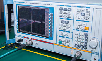
In-stock items can be shipped within 24 hours. Some parts will be arranged for delivery within 1-2 days from the date all items arrive at our warehouse. And Allelco ships order once a day at about 17:00, except Sunday. Once the goods are shipped, the estimated delivery time depends on the shipping methods and Delivery destination. The table below shows are the logistic time for some common countries.

Delivery Cost

  1. Use your express account for shipment if you have one.
  2. Use our account for the shipment. Refer to the table below for the approximate charges.
(Different time frame / countries / package size has different price.)

Delivery Method

  1. Global Common Shipment by DHL / UPS / FedEx / TNT / EMS / SF we support.
  2. Others more shipping ways, please get in touch with your customer manager.

Common Countries Logistic Time Reference
Region Country Logistic Time(Day)
America United States 5
Brazil 7
Europe Germany 5
United Kingdom 4
Italy 5
Oceania Australia 6
New Zealand 5
Asia India 4
Japan 4
Middle East Israel 6
DHL & FedEx Shipment Charges Reference
Shipment charges(KG) Reference DHL(USD$)
0.00kg-1.00kg USD$30.00 - USD$60.00
1.00kg-2.00kg USD$40.00 - USD$80.00
2.00kg-3.00kg USD$50.00 - USD$100.00
Note:
The above table is for reference only. There may have some data bias for the uncontrollable factors.
Contact us if you have any questions.
  • QC (Quality Warranty)
  • Payment Support
  • Packaging

QC (Quality Warranty)

Allelco is committed to exceeding customer expectations through customer service excellence, order accuracy, and on-time delivery.
This is achieved through our commitment to the continual improvement of our processes, services, and products.


Strict quality inspection builds a solid foundation for electronic component quality.
  1. Visual inspection
  2. Performance testing and reliability verification
  3. Standardized full-process testing
  4. Precise control of every parameter
We eliminate defective components and ensure the stable operation of electronic devices through professional quality standards.

Payment Support

The payment method can be chosen from the methods shown below: Wire Transfer (T/T, Bank Transfer), Western Union, Credit card, PayPal.
  • HKBea
  • Paypal
  • MasterCard
  • Western-Union
  • VISA
Stable Delivery, Sincere Partnership — Your Faithful Supply Chain Partner
  • Efficient Supply Management
  • Cost-Saving Procurement
  • Fast Sourcing & Delivery
Contact us if you have any questions.

Packaging

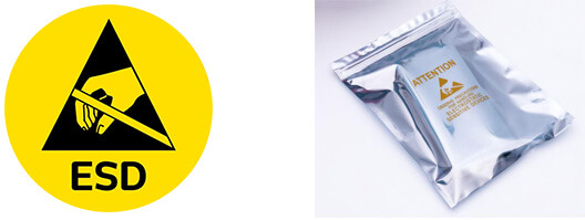
Electrostatic Discharge Protection and Handling

All electrostatic-sensitive components are handled in accordance with electrostatic discharge control procedures. The products are hermetically sealed in anti-static safe packaging to prevent electrostatic damage. Appropriate labeling is also applied for identification and traceability. This ensures product integrity during storage, handling and transportation.


ESD
Samtec Inc.

TSW-209-21-L-S-RA

Samtec Inc.
98D-TSW-209-21-L-S-RA

Want a better price? Add to Cart and Submit RFQ now, we'll contact you immediately.

0 RFQ
Shopping cart (0 Items)
It is empty.
Compare List (0 Items)
It is empty.
Feedback

Your feedback matters! At Allelco, we value the user experience and strive to improve it constantly.
Please share your comments with us via our feedback form, and we'll respond promptly.
Thank you for choosing Allelco.

Subject
E-mail
Comments
Captcha
Drag or click to upload file
Upload File
types: .xls, .xlsx, .doc, .docx, .jpg, .png and .pdf.
Max file size: 10MB