View All

Please refer to the English Version as our Official Version.Return

Europe
France(Français) Germany(Deutsch) Italy(Italia) Russian(русский) Poland(polski) Czech(Čeština) Luxembourg(Lëtzebuergesch) Netherlands(Nederland) Iceland(íslenska) Hungarian(Magyarország) Spain(español) Portugal(Português) Turkey(Türk dili) Bulgaria(Български език) Ukraine(Україна) Greece(Ελλάδα) Israel(עִבְרִית) Sweden(Svenska) Finland(Svenska) Finland(Suomi) Romania(românesc) Moldova(românesc) Slovakia(Slovenská) Denmark(Dansk) Slovenia(Slovenija) Slovenia(Hrvatska) Croatia(Hrvatska) Serbia(Hrvatska) Montenegro(Hrvatska) Bosnia and Herzegovina(Hrvatska) Lithuania(lietuvių) Spain(Português) Switzerland(Deutsch) United Kingdom(English)
Asia/Pacific
Japan(日本語) Korea(한국의) Thailand(ภาษาไทย) Malaysia(Melayu) Singapore(Melayu) Vietnam(Tiếng Việt) Philippines(Pilipino)
Africa, India and Middle East
United Arab Emirates(العربية) Iran(فارسی) Tajikistan(فارسی) India(हिंदी) Madagascar(malaɡasʲ)
South America / Oceania
New Zealand(Maori) Brazil(Português) Angola(Português) Mozambique(Português)
North America
United States(English) Canada(English) Haiti(Ayiti) Mexico(español)
HomeProductsCapacitorsCeramic CapacitorsC1608X6S1C155K080AC
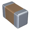
C1608X6S1C155K080AC Image
Image may be representation.
See specifications for product details.
EXPRESS OPTION
Payment method

C1608X6S1C155K080AC - TDK Corporation

Manufacturer Part Number
C1608X6S1C155K080AC
Manufacturer
TDK Corporation
Allelco Part Number
32D-C1608X6S1C155K080AC
Warranty
1 Year Allelco Warranty - Find out more
Stock Status:
731,800 pcs available, New & Original
Parts Description
CAP CER 1.5UF 16V X6S 0603
Package
0603 (1608 Metric)
Data sheet
C1608X6S1C155K0.pdf
RoHs Status
Lead free / RoHS Compliant
Our certification
In stock: 731800

Required fields are indicated by an asterisk (*)
Please send RFQ, we will respond immediately.

Quantity

Specifications

C1608X6S1C155K080AC Tech Specifications
TDK Corporation - C1608X6S1C155K080AC technical specifications, attributes, parameters and parts with similar specifications to TDK Corporation - C1608X6S1C155K080AC

Product Attribute Attribute Value
Manufacturer TDK Corporation
Voltage - Rated 16V
Tolerance ±10%
Thickness (Max) 0.035" (0.90mm)
Temperature Coefficient X6S
Size / Dimension 0.063" L x 0.032" W (1.60mm x 0.80mm)
Series C
Ratings -
Packaging Tape & Reel (TR)
Package / Case 0603 (1608 Metric)
Other Names 445-14211-2
C1608X6S1C155KTJ00E
Operating Temperature -55°C ~ 105°C
Product Attribute Attribute Value
Mounting Type Surface Mount, MLCC
Moisture Sensitivity Level (MSL) 1 (Unlimited)
Lead Style -
Lead Spacing -
Lead Free Status / RoHS Status Lead free / RoHS Compliant
Height - Seated (Max) -
Features Low ESL
Failure Rate -
Detailed Description 1.5µF ±10% 16V Ceramic Capacitor X6S 0603 (1608 Metric)
Capacitance 1.5µF
Applications General Purpose

Environmental & Export Classifications

ATTRIBUTE DESCRIPTION
RoHs Status Lead free / RoHS Compliant

Frequently Asked Questions(FAQ)

What makes the C1608X6S1C155K080AC suitable for decoupling applications compared to X5R or X7S alternatives?
The C1608X6S1C155K080AC uses X6S dielectric, which provides a stable capacitance range of ±15% across -55°C to 105°C with predictable voltage derating. Unlike X5R alternatives such as the C1608X5R0J155M080AB, the X6S formulation in the C1608X6S1C155K080AC maintains tighter tolerance control (±10%) and exhibits lower capacitance drift under thermal cycling. This stability is critical for decoupling where frequency response consistency matters. X7S formulations like the C1608X7S1C155K080AC provide wider temperature range but with ±22% tolerance, introducing uncontrolled variation in ripple rejection. For power supply rails operating between 0°C and 85°C, the C1608X6S1C155K080AC delivers predictable ESR and ESL characteristics without the aggressive derating seen in high-K X7S materials.
How does the low ESL design of the C1608X6S1C155K080AC affect high-frequency noise filtering performance?
The C1608X6S1C155K080AC is specified with low ESL (equivalent series inductance) architecture, which extends the effective impedance floor to higher frequencies. At 100 MHz, low-ESL 0603 MLCCs typically maintain impedance below 100 mΩ, compared to 200+ mΩ for standard construction. This characteristic shifts the self-resonant frequency (SRF) of the C1608X6S1C155K080AC upward, meaning the capacitor remains useful for filtering noise above 1 GHz rather than becoming inductive at lower frequencies. For mixed-signal boards with clock harmonics extending to 2–3 GHz, pairing the C1608X6S1C155K080AC with larger bulk capacitors (10–47 µF) creates a more effective impedance curve across the frequency spectrum. The low ESL design also reduces ringing and voltage overshoot on fast transients, particularly beneficial in 3.3V digital rails with sub-nanosecond edge rates.
Can the C1608X6S1C155K080AC be used in 5V applications despite its 16V rating?
Yes, the C1608X6S1C155K080AC is fully suitable for 5V applications; the 16V rating provides derating margin and reliability headroom. Operating at 5V nominal represents 31% of the rated voltage, well within safe operating limits. For 5V rails with transient overshoot up to 5.5V (10% spike), the C1608X6S1C155K080AC maintains stable performance with negligible capacitance change. However, if the application experiences sustained voltages above 16V or repeated transients exceeding 18V, the 16V rating of the C1608X6S1C155K080AC becomes limiting. In such cases, higher-voltage options like 25V variants would be necessary. The ±10% tolerance specification of the C1608X6S1C155K080AC assumes operation within its rated voltage envelope; exceeding 16V voids this tolerance guarantee and increases leakage current risk.
How should the C1608X6S1C155K080AC be handled during assembly to avoid moisture damage despite MSL 1 rating?
The C1608X6S1C155K080AC carries MSL 1 (Moisture Sensitivity Level 1), indicating unlimited shelf life without drying requirements when stored below 30°C and 60% relative humidity. This is one of the lowest moisture-risk classifications for ceramic capacitors. However, 'unlimited' does not mean immune to damage during reflow. Incoming C1608X6S1C155K080AC parts that have been exposed to high humidity (>80% RH) for extended periods should still be dried at 125°C for 24 hours before assembly to prevent delamination during the 260°C peak reflow cycle. The 0603 package size means thermal shock is more severe than larger formats. After moisture exposure events (such as inventory stored in non-conditioned warehouses), drying the C1608X6S1C155K080AC batch is a low-cost insurance step. Tape reel storage in desiccant bags is recommended practice even for MSL 1 components.
What is the actual capacitance range expected from production samples of the C1608X6S1C155K080AC, and how does this affect circuit tuning?
The C1608X6S1C155K080AC is specified at 1.5 µF ±10%, meaning acceptable production samples will range from 1.35 µF to 1.65 µF at 25°C and rated voltage (16V). This ±10% tolerance results from dielectric material variation and electrode thickness control during manufacturing. For analog filter designs requiring Q > 5 or precise cutoff frequencies, the tolerance stack of multiple C1608X6S1C155K080AC units can push actual circuit performance ±10–15% away from theoretical values. In RC filter designs with target corner frequencies between 10 kHz and 100 kHz, using trimmers or higher-tolerance resistors (1% metal film) with the C1608X6S1C155K080AC helps compensate. For switched-mode applications (buck converters, boost converters) where capacitance variation affects switching frequency by 5–8%, the C1608X6S1C155K080AC tolerance is typically acceptable because feedback loops regulate final output. Worst-case analysis should account for both the ±10% tolerance of the C1608X6S1C155K080AC and additional derating from thermal and voltage stress.
How does the C1608X6S1C155K080AC compare to the C1608X5R1C155M080AB in terms of voltage derating and temperature stability?
Both the C1608X6S1C155K080AC (X6S, ±10%) and the C1608X5R1C155M080AB (X5R, ±15%) are 1.5 µF options, but they diverge significantly in thermal behavior. X5R materials used in the C1608X5R1C155M080AB are optimized for flat capacitance across -55°C to 85°C (tighter range than X6S), with ±15% tolerance across this band. The C1608X6S1C155K080AC extends the operating range to 105°C, accepting slightly broader tolerance (±10% but to 105°C rather than 85°C). Voltage derating curves differ: X5R ceramics in the C1608X5R1C155M080AB show mild derating at 16V, while X6S in the C1608X6S1C155K080AC exhibits stronger voltage derating starting around 10V. For applications limited to 0–85°C, the C1608X5R1C155M080AB often delivers more predictable performance. For industrial equipment spanning -40°C to 85°C or higher, the C1608X6S1C155K080AC's extended upper temperature limit (105°C) becomes the correct choice despite slightly less flat characteristics. The tolerance difference (±10% vs ±15%) is secondary to the temperature range decision.
What is the expected ESR and ESL of the C1608X6S1C155K080AC at 1 MHz, and how does this compare to larger package alternatives?
Production data for 0603 MLCCs like the C1608X6S1C155K080AC typically shows ESR in the range of 50–150 mΩ at 1 MHz, depending on internal construction and lead attachment method. ESL for the C1608X6S1C155K080AC in tape reel form averages 0.3–0.5 nH, translating to inductive reactance of roughly 2–3 mΩ at 1 MHz. Combined impedance at 1 MHz is dominated by ESR; ESL contribution becomes significant above 10 MHz. The low-ESL design mentioned in the C1608X6S1C155K080AC specification helps maintain impedance below 150 mΩ through the megahertz range. Compared to 1206 or 1210 packages (which have larger footprints and lower ESL due to shorter leads), the C1608X6S1C155K080AC trades some ESL advantage for PCB routing simplicity and bill-of-materials cost. For power supply decoupling where impedance at 10–100 MHz is critical, combining multiple C1608X6S1C155K080AC units (3–5 in parallel) often outperforms a single larger capacitor due to ESL reduction through parallel connection.
Is the C1608X6S1C155K080AC suitable for use as a charge storage capacitor in low-speed analog circuits, or should higher-tolerance parts be selected?
For general-purpose charge storage in sample-and-hold circuits, integrators, or transimpedance amplifiers operating below 100 kHz, the ±10% tolerance of the C1608X6S1C155K080AC is often marginal. Analog designs requiring charge precision (such as precision DAC buffering) typically specify ±5% or tighter tolerances. The C1608X6S1C155K080AC at ±10% can introduce 1.5–2 LSB errors in 8-bit resolution circuits. If the circuit topology includes trimmer resistors or software calibration, the C1608X6S1C155K080AC becomes acceptable because final accuracy is corrected post-production. For time-constant applications (RC filters with 1–10 second decay), the ±10% tolerance translates to predictable but uncompensated timing variation. Alternatives like C0G/NP0 dielectrics (available in smaller capacitance values) provide ±5% tolerance at higher cost and voltage derating. If tolerance is non-negotiable, specifying C1608X6S1C155K080AC in production but screening to the tighter 0–5% bin adds cost but ensures consistency.
What are the RoHS and REACH implications of the C1608X6S1C155K080AC for military or automotive qualification?
The C1608X6S1C155K080AC is marked RoHS3 Compliant, confirming absence of lead, cadmium, mercury, and hexavalent chromium in materials and solder. REACH Unaffected status means the component is not subject to EU REACH Regulation restrictions or substances of concern (candidate list inclusion unlikely). For commercial and industrial applications, the C1608X6S1C155K080AC meets standard RoHS/REACH expectations. However, military applications (MIL-PRF-32019 or equivalent) typically require additional documentation: Certificate of Conformance, material composition traceability, and counterfeit-prevention documentation not typically provided for the C1608X6S1C155K080AC unless specifically sourced through military-grade channels. Automotive qualifications (AEC-Q200) may require extended temperature testing and derating curves beyond standard datasheets. The C1608X6S1C155K080AC in commodity supply chains is not pre-qualified for these end uses. If automotive or military use is intended, engage with TDK or authorized distributors for qualified variants and full traceability documentation.
How does the C1608X6S1C155K080AC perform under extended bias stress, and what leakage current degradation should be expected after 1000 hours?
MLCC aging under constant DC bias is primarily driven by insulation resistance (IR) degradation rather than capacitance loss. For the C1608X6S1C155K080AC operating at 16V continuous bias, IR typically decreases from initial >1 GΩ to 100–500 MΩ after 1000 hours of operation at 85°C, representing predictable electromechanical relaxation in the ceramic dielectric. Leakage current specification for 1.5 µF MLCCs is often given as CV/1000 or CV/2000, where CV is the capacitance-voltage product (1.5 × 16 = 24 µC). At 24 µC / 2000 = 12 µA initial maximum, the C1608X6S1C155K080AC may drift to 20–30 µA after thermal aging. For low-power analog circuits, this aging effect is measurable but tolerable. In high-impedance transimpedance amplifier inputs or precision analog switches, the C1608X6S1C155K080AC's leakage current (whether initial or aged) may introduce offset errors of millivolts across high-impedance nodes. Screening or derating the C1608X6S1C155K080AC to lower voltage (12V instead of 16V) reduces the initial leakage budget and slows aging progression.
What is the thermal shock risk when the C1608X6S1C155K080AC transitions from -55°C to 105°C storage and operational extremes?
The C1608X6S1C155K080AC is rated for continuous operation from -55°C to 105°C, but the specification does not typically address thermal shock rate (degrees per second). However, aerospace and industrial equipment specifications often impose thermal cycling limits (e.g., -55°C to 85°C in 15-minute cycles). For the C1608X6S1C155K080AC, the primary failure mechanism under thermal shock is solder joint cracking or internal electrode fracture due to coefficient-of-thermal-expansion (CTE) mismatch between the ceramic body and PCB. 0603 packages are relatively robust due to small footprint, but rapid cycling (>5°C per second) accelerates degradation. In automotive applications subject to engine bay temperature swings (60°C change in 10 seconds), the C1608X6S1C155K080AC is less prone to failure than larger capacitors because thermal penetration time is shorter. However, repeated thermal transients over 50 cycles may introduce 5–10% IR degradation. Design practices should avoid direct thermal coupling between the C1608X6S1C155K080AC and hot surfaces; maintaining PCB substrate thermal gradients <20°C/cm around the component reduces stress.

Parts with Similar Specifications

The three parts on the right have similar specifications to TDK Corporation C1608X6S1C155K080AC

Product Attribute C1608X6S1C105K080AC C1608X6S1C155M080AC C1608X6S1C225K080AC C1608X6S1C335K080AC
Part Number C1608X6S1C105K080AC C1608X6S1C155M080AC C1608X6S1C225K080AC C1608X6S1C335K080AC
Manufacturer TDK Corporation TDK Corporation TDK Corporation TDK Corporation
Operating Temperature - -40°C ~ 85°C 0°C ~ 70°C -40°C ~ 85°C
Thickness (Max) - - - -
Lead Free Status / RoHS Status - - - -
Capacitance - - - -
Series - - - -
Moisture Sensitivity Level (MSL) - - - -
Lead Style - - - -
Features - - - Simultaneous Sampling
Other Names - - - -
Ratings - - - -
Voltage - Rated - - - -
Package / Case - 196-LFBGA 16-DIP (0.300', 7.62mm) 64-VFQFN Exposed Pad
Temperature Coefficient - - - -
Lead Spacing - - - -
Applications - - - -
Detailed Description - - - -
Packaging - - - -
Failure Rate - - - -
Size / Dimension - - - -
Mounting Type - Surface Mount Through Hole Surface Mount
Tolerance - - - -
Height - Seated (Max) - - - -

C1608X6S1C155K080AC Datasheet PDF

Download C1608X6S1C155K080AC pdf datasheets and TDK Corporation documentation for C1608X6S1C155K080AC - TDK Corporation.

Datasheets
C Series, General Datasheet.pdf C Series, Gen Appl & Mid-Voltage Spec.pdf MLCC Part Number Guide .pdf

Customer Reviews

Evaluation: 10 Articles

  • ECUb***h
    Sep 22, 2026

    Used for repair of an older automotive ECU. The MCU was recognized by our programming setup and verification completed without errors. The repaired board now starts and communicates normally.

  • RS48***ieldTech
    Sep 16, 2026

    Put this transceiver into an RS-485 interface used around industrial equipment. Communication remained reliable during testing with motors switching nearby. Good result for the replacement board.

  • Logi***b_Chris
    Sep 8, 2026

    Purchased for a Cyclone III development project. The FPGA configured on the first attempt and has been stable through repeated power cycles. No problems with the I/O we are using.

  • Circ***FixerTom
    Sep 2, 2026

    Used this rectifier in a high-current power supply repair. Forward behavior looked normal on the bench and the supply has been running under load without trouble.

  • Retr***UWorks
    Aug 31, 2026

    Needed the exact ST10F269Z2Q6 for servicing an older control unit. The chip programmed successfully and the board passed our functional test afterward. Much easier than redesigning around a newer MCU.

  • Andr***PCBLab
    Aug 28, 2026

    I needed this ADC for an older data acquisition board. Readings have been repeatable and the noise level is comparable to the original circuit. Happy with the purchase.

  • Leat***O'Keefe
    Aug 20, 2026

    one of my hobbies is skydiving. and when i'm skydiving this works great.

  • Ilen***
    Aug 20, 2026

    This product works considerably well. It secretly improves my basketball by a lot.

  • Indu***ialPower
    Aug 17, 2026

    Installed this IGBT module in a power conversion cabinet. Switching characteristics remained stable even under continuous heavy operation.

  • Nikh***ech
    Aug 13, 2026

    Great low-power MCU for portable equipment. Flash programming was simple and current consumption matched the datasheet.

Write a Review

Your Email address will not be published.

Shipment

Delivery Time

In-stock items can be shipped within 24 hours. Some parts will be arranged for delivery within 1-2 days from the date all items arrive at our warehouse. And Allelco ships order once a day at about 17:00, except Sunday. Once the goods are shipped, the estimated delivery time depends on the shipping methods and Delivery destination. The table below shows are the logistic time for some common countries.

Delivery Cost

  1. Use your express account for shipment if you have one.
  2. Use our account for the shipment. Refer to the table below for the approximate charges.
(Different time frame / countries / package size has different price.)

Delivery Method

  1. Global Common Shipment by DHL / UPS / FedEx / TNT / EMS / SF we support.
  2. Others more shipping ways, please get in touch with your customer manager.

Common Countries Logistic Time Reference
Region Country Logistic Time(Day)
America United States 5
Brazil 7
Europe Germany 5
United Kingdom 4
Italy 5
Oceania Australia 6
New Zealand 5
Asia India 4
Japan 4
Middle East Israel 6
DHL & FedEx Shipment Charges Reference
Shipment charges(KG) Reference DHL(USD$)
0.00kg-1.00kg USD$30.00 - USD$60.00
1.00kg-2.00kg USD$40.00 - USD$80.00
2.00kg-3.00kg USD$50.00 - USD$100.00
Note:
The above table is for reference only. There may have some data bias for the uncontrollable factors.
Contact us if you have any questions.
  • QC (Quality Warranty)
  • Payment Support
  • Packaging
  • Certifications & Memberships

QC (Quality Warranty)

Allelco is committed to exceeding customer expectations through customer service excellence, order accuracy, and on-time delivery.
This is achieved through our commitment to the continual improvement of our processes, services, and products.


Strict quality inspection builds a solid foundation for electronic component quality.
  1. Visual inspection
  2. Performance testing and reliability verification
  3. Standardized full-process testing
  4. Precise control of every parameter
We eliminate defective components and ensure the stable operation of electronic devices through professional quality standards.

Payment Support

The payment method can be chosen from the methods shown below: Wire Transfer (T/T, Bank Transfer), Western Union, Credit card, PayPal.
  • HKBea
  • Paypal
  • MasterCard
  • Western-Union
  • VISA
Stable Delivery, Sincere Partnership — Your Faithful Supply Chain Partner
  • Efficient Supply Management
  • Cost-Saving Procurement
  • Fast Sourcing & Delivery
Contact us if you have any questions.

Packaging

Electrostatic Discharge Protection and Handling

All electrostatic-sensitive components are handled in accordance with electrostatic discharge control procedures. The products are hermetically sealed in anti-static safe packaging to prevent electrostatic damage. Appropriate labeling is also applied for identification and traceability. This ensures product integrity during storage, handling and transportation.


ESD

Certifications & Memberships

Third-party certified, strict quality control. Our certification
  • ISO 9001: 2015
  • ISO 13485: 2016
  • ISO 14001: 2015
  • ISO 28000: 2007
  • ISO 45001: 2018
  • GB/T 27922-2011
  • SMTA
  • IPC
  • ESD
  • PSMA
C1608X6S1C155K080AC Image

C1608X6S1C155K080AC

TDK Corporation
32D-C1608X6S1C155K080AC

Want a better price? Add to Cart and Submit RFQ now, we'll contact you immediately.

0 RFQ
Shopping cart (0 Items)
It is empty.
Compare List (0 Items)
It is empty.
Feedback

Your feedback matters! At Allelco, we value the user experience and strive to improve it constantly.
Please share your comments with us via our feedback form, and we'll respond promptly.
Thank you for choosing Allelco.

Subject
E-mail
Comments
Captcha
Drag or click to upload file
Upload File
types: .xls, .xlsx, .doc, .docx, .jpg, .png and .pdf.
Max file size: 10MB