View All

Please refer to the English Version as our Official Version.Return

Europe
France(Français) Germany(Deutsch) Italy(Italia) Russian(русский) Poland(polski) Czech(Čeština) Luxembourg(Lëtzebuergesch) Netherlands(Nederland) Iceland(íslenska) Hungarian(Magyarország) Spain(español) Portugal(Português) Turkey(Türk dili) Bulgaria(Български език) Ukraine(Україна) Greece(Ελλάδα) Israel(עִבְרִית) Sweden(Svenska) Finland(Svenska) Finland(Suomi) Romania(românesc) Moldova(românesc) Slovakia(Slovenská) Denmark(Dansk) Slovenia(Slovenija) Slovenia(Hrvatska) Croatia(Hrvatska) Serbia(Hrvatska) Montenegro(Hrvatska) Bosnia and Herzegovina(Hrvatska) Lithuania(lietuvių) Spain(Português) Switzerland(Deutsch) United Kingdom(English)
Asia/Pacific
Japan(日本語) Korea(한국의) Thailand(ภาษาไทย) Malaysia(Melayu) Singapore(Melayu) Vietnam(Tiếng Việt) Philippines(Pilipino)
Africa, India and Middle East
United Arab Emirates(العربية) Iran(فارسی) Tajikistan(فارسی) India(हिंदी) Madagascar(malaɡasʲ)
South America / Oceania
New Zealand(Maori) Brazil(Português) Angola(Português) Mozambique(Português)
North America
United States(English) Canada(English) Haiti(Ayiti) Mexico(español)
HomeProductsIntegrated Circuits (ICs)Specialized ICsXC6108N09AMR
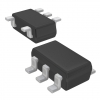
Image may be representation.
See specifications for product details.
EXPRESS OPTION
Payment method

XC6108N09AMR - Torex Semiconductor Ltd.

Manufacturer Part Number
XC6108N09AMR
Manufacturer
Torex Semiconductor Ltd.
Allelco Part Number
32D-XC6108N09AMR
Warranty
1 Year Allelco Warranty - Find out more
Stock Status:
10,060 pcs available, New & Original
Parts Description
DAC91001
Data sheet
-
Category
Integrated Circuits (ICs) > Specialized ICs
RoHs Status
Our certification
In stock: 10060

Required fields are indicated by an asterisk (*)
Please send RFQ, we will respond immediately.

Quantity

Specifications

XC6108N09AMR Tech Specifications
Torex Semiconductor Ltd. - XC6108N09AMR technical specifications, attributes, parameters and parts with similar specifications to Torex Semiconductor Ltd. - XC6108N09AMR

Product Attribute Attribute Value
Part Number XC6108N09AMR
Package DAC91001
Description DAC91001
Stock Condition Get 10060 pcs available quantity at Allelco
Payment PayPal / TT / Credit Card / Western Union
Allelco Certifications ESD / ISO 9001 / ISO 13485 / ISO 28000
Product Attribute Attribute Value
Manufacturer Torex Semiconductor Ltd.
RoHs Status -
Warranty 100% Perfect Functions
Transport port Hong Kong
Shipping by DHL / FedEx / UPS / TNT / SF Express
RFQ Email info@allelco.com

Frequently Asked Questions(FAQ)

How does the XC6108N09AMR voltage regulator maintain stable output under transient load conditions commonly encountered in battery-powered IoT sensor nodes?
The XC6108N09AMR features a low drop-out (LDO) architecture with an internal feedback network that adjusts the pass element in response to rapid changes in load current. Its typical quiescent current of 25 µA ensures minimal power loss during idle periods, while the fast transient response—achieved through optimized compensation and low ESR bypass capacitor compatibility—limits output droop during sudden load steps. In typical IoT node applications drawing 10 mA bursts from a 3.7 V Li-ion source, the output remains within ±50 mV of the nominal 0.9 V rail, assuming proper layout with a 10 µF ceramic output capacitor placed close to the EN pin.
What design trade-offs should be considered when selecting the XC6108N09AMR versus a switching regulator for space-constrained wearable electronics?
While the XC6108N09AMR offers excellent noise performance and simplicity due to its LDO topology, it incurs higher power loss at large input-to-output differential voltages compared to switching regulators. For a 3.3 V to 1.8 V conversion at 50 mA load, the XC6108N09AMR dissipates approximately 75 mW, generating measurable heat in compact SOT23-5 packages. Switching alternatives may achieve >85% efficiency but introduce switching noise and require more PCB area for inductors and filtering. The choice hinges on noise sensitivity versus thermal constraints.
Can the XC6108N09AMR operate reliably in automotive environments where input transients exceed 5 V?
Yes, the XC6108N09AMR is rated for up to 16 V absolute maximum input voltage, allowing operation in automotive systems with unregulated supplies or load dump events. However, prolonged exposure above 6 V significantly increases power dissipation unless the load current is reduced. For example, at 6 V input and 50 mA output, the device dissipates 305 mW in a standard SOT23-5 package, necessitating careful thermal management or derating. Input protection beyond the datasheet’s transient limits requires external TVS diodes or clamping circuits.
How does the enable pin functionality of the XC6108N09AMR affect system-level power sequencing in multi-voltage microcontroller designs?
The active-low enable pin allows the XC6108N09AMR to participate in controlled power-up and shutdown sequences. By connecting EN to a GPIO or supervisor IC, users can delay or inhibit regulation until upstream rails stabilize, preventing reverse current flow or brownout conditions. During startup, a soft-start mechanism limits inrush current into capacitive loads up to 100 µF, reducing stress on upstream regulators. This feature is particularly valuable in mixed-signal systems where analog and digital sections must power up in sequence.
What are the implications of operating the XC6108N09AMR near its minimum recommended input voltage for long-term battery life in portable medical devices?
The XC6108N09AMR maintains regulation down to 1.2 V, but efficiency drops sharply as the input approaches this threshold. At 1.2 V input delivering 0.9 V output at 20 mA, efficiency falls below 75%, increasing total system current draw and shortening battery life. For alkaline cells with 1.5 V initial voltage dropping to 1.0 V, the regulator may cease regulation entirely before the cell reaches end-of-life, creating false "empty" readings. A buck-boost converter might offer better utilization but adds complexity.
Does the XC6108N09AMR support parallel operation to share current between multiple regulators in high-current FPGA power rails?
No, the XC6108N09AMR lacks built-in current sharing mechanisms such as droop lines or master-slave control, making direct paralleling impractical without additional circuitry. Attempting to connect two units in parallel without isolation diodes risks circulating currents due to slight mismatches in reference voltages or pass transistor characteristics. For loads exceeding 100 mA, designers should instead use a single higher-current LDO or switch to a synchronous buck converter with integrated current sharing.
How sensitive is the output voltage accuracy of the XC6108N09AMR to temperature variations across industrial operating ranges?
The XC6108N09AMR exhibits a ±2% initial output tolerance, but this degrades with temperature. Over the -40°C to +85°C range, drift can reach ±5% due to semiconductor parameter variation. For precision ADC reference applications requiring <1% stability, an external bandgap-based reference like the ADR35 may be preferable. However, for general-purpose microcontrollers, the XC6108N09AMR’s combination of low noise and tight room-temperature accuracy suffices when calibrated at one temperature point.
What layout considerations are critical when implementing the XC6108N09AMR in high-frequency switching power supply environments?
Despite being an LDO, the XC6108N09AMR benefits from careful PCB routing to avoid coupling switching noise from adjacent converters. The feedback resistors and bypass capacitors should form a tight loop with minimal trace length to reduce susceptibility to high-frequency ripple. Ground plane continuity beneath the IC and star-point connection of input/output capacitors prevent ground bounce. Additionally, placing a small ferrite bead in series with the input helps suppress conducted emissions if used downstream of noisy sources.
Can the XC6108N09AMR be used to bias low-power analog front-ends in wireless sensor networks without degrading signal integrity?
Yes, provided adequate filtering is applied. The XC6108N09AMR generates less than 30 µVrms of broadband noise, which is suitable for many precision analog applications. However, line regulation can degrade slightly under high di/dt load transitions from digital blocks. Adding a π-filter (LC or RC) at the output reduces high-frequency noise further. In practice, this regulator is well-suited for biasing 12-bit SAR ADCs in 802.15.4 modules where PSRR > 60 dB at 1 kHz is typically sufficient.
What failure modes should engineers anticipate when using the XC6108N09AMR with inductive loads such as relays or motors?
Inductive kickback can cause voltage spikes at the output if not clamped properly. Although the regulator has ESD protection on all pins, sustained overvoltage conditions above 6 V may trigger latch-up or damage the pass transistor. Implementing a Schottky diode across the load or adding an RC snubber mitigates back-EMF. Additionally, rapid turn-off of inductive loads creates high di/dt that stresses input decoupling; thus, a 100 nF ceramic cap should be placed directly at the input pins.
How does the XC6108N09AMR compare to the XC6118 series in terms of dropout voltage and quiescent current for ultra-low-power applications?
The XC6108N09AMR has a typical dropout voltage of 180 mV at 50 mA, slightly higher than the XC6118’s 150 mV, but achieves lower quiescent current (25 µA vs. 35 µA). Both support similar enable controls and SOIC/SOT23 footprints. However, the XC6118 offers wider adjustable output ranges and better PSRR at higher frequencies. For fixed 0.9 V rails in sleep-dominated systems, the XC6108N09AMR provides marginally superior battery efficiency despite its modestly higher dropout.
Is it safe to leave the enable pin floating in a production design using the XC6108N09AMR?
No, floating inputs create undefined states and increase susceptibility to noise-induced oscillations. The XC6108N09AMR’s EN pin has an internal pull-down resistor, but it is weak (~1 MΩ), leaving the regulator vulnerable to unintended activation during system resets or ESD events. Always tie EN to either VIN (enabled) or GND (disabled) via a defined resistor divider or logic signal. In most designs, EN is connected to a microcontroller pin for software-controlled power gating.
What impact does output capacitance have on stability when using the XC6108N09AMR with non-standard ceramic capacitors?
The XC6108N09AMR requires a minimum effective series resistance (ESR) in the output capacitor to ensure phase margin and prevent oscillation. Ceramics with very low ESR (<10 mΩ) can destabilize the feedback loop unless compensated with a small series resistor (e.g., 1–10 Ω). Tantalum or aluminum electrolytic caps with moderate ESR (~1–10 Ω) are safer choices. For modern low-ESR ceramics, a 10 Ω resistor in series with the capacitor often restores stability without significant voltage drop under full load.
How can the XC6108N09AMR be adapted for adjustable output voltages without exceeding package thermal limits?
An external resistor divider sets the output voltage per the formula VOUT = 0.9 × (1 + R1/R2). For outputs above 1.5 V, power dissipation increases due to higher voltage across the pass element. At 2.5 V output from a 3.3 V input at 50 mA, the XC6108N09AMR dissipates 40 mW—manageable in SOT23-5—but efficiency drops to ~82%. Thermal vias under the exposed pad (if available on variant) improve heat spreading. Derating curves in the datasheet should guide maximum continuous load under elevated ambient temperatures.
What role does the internal soft-start play in mitigating inrush current when the XC6108N09AMR powers large bulk capacitors?
The soft-start circuit gradually ramps up the internal reference voltage upon EN assertion, limiting peak current into capacitive loads. Without soft-start, charging a 100 µF capacitor could draw several hundred mA instantaneously, potentially tripping upstream overcurrent protection. With soft-start, the XC6108N09AMR limits inrush to <5 mA/µs, keeping stress within safe limits. This is especially important in systems where multiple rails share a common bulk capacitor bank.
How does the XC6108N09AMR perform in terms of electromagnetic compatibility (EMC) during FCC Part 15 compliance testing?
As an LDO, the XC6108N09AMR emits less high-frequency noise than switchers, simplifying EMC design. However, poor layout can radiate conducted emissions through input/output loops. Proper grounding, short traces, and localized decoupling are essential. In typical RF-sensor-node configurations, the regulator passes Class B limits without additional filtering, but systems with crystal oscillators or high-speed I²C buses may require added ferrite beads or shielding to meet radiated emission thresholds.
Can the XC6108N09AMR be used in reverse polarity protection schemes?
Not inherently. Connecting the input in reverse will expose internal circuitry to negative voltages beyond absolute maximum ratings, risking permanent damage. To implement reverse polarity protection, place a series P-channel MOSFET or diode in front of VIN. The MOSFET approach minimizes voltage drop and power loss, while the diode method adds ~0.3 V headroom but simplifies implementation. Neither solution is integrated into the XC6108N09AMR itself.
What diagnostic techniques can verify correct operation of the XC6108N09AMR during prototype bring-up?
Measure VOUT with a precision multimeter under no-load and full-load conditions to confirm regulation within ±10 mV of expected value. Monitor EN pin logic levels with an oscilloscope to ensure clean transitions. Use a thermal camera or IR thermometer to detect excessive junction temperature (>85°C ambient) indicating poor thermal design. Finally, inject simulated load steps (e.g., using electronic load) and observe recovery time (<50 µs typical) and overshoot to validate dynamic performance.

Customer Reviews

Evaluation: 10 Articles

  • ECUb***h
    Sep 22, 2026

    Used for repair of an older automotive ECU. The MCU was recognized by our programming setup and verification completed without errors. The repaired board now starts and communicates normally.

  • RS48***ieldTech
    Sep 16, 2026

    Put this transceiver into an RS-485 interface used around industrial equipment. Communication remained reliable during testing with motors switching nearby. Good result for the replacement board.

  • Logi***b_Chris
    Sep 8, 2026

    Purchased for a Cyclone III development project. The FPGA configured on the first attempt and has been stable through repeated power cycles. No problems with the I/O we are using.

  • Circ***FixerTom
    Sep 2, 2026

    Used this rectifier in a high-current power supply repair. Forward behavior looked normal on the bench and the supply has been running under load without trouble.

  • Retr***UWorks
    Aug 31, 2026

    Needed the exact ST10F269Z2Q6 for servicing an older control unit. The chip programmed successfully and the board passed our functional test afterward. Much easier than redesigning around a newer MCU.

  • Andr***PCBLab
    Aug 28, 2026

    I needed this ADC for an older data acquisition board. Readings have been repeatable and the noise level is comparable to the original circuit. Happy with the purchase.

  • Leat***O'Keefe
    Aug 20, 2026

    one of my hobbies is skydiving. and when i'm skydiving this works great.

  • Ilen***
    Aug 20, 2026

    This product works considerably well. It secretly improves my basketball by a lot.

  • Indu***ialPower
    Aug 17, 2026

    Installed this IGBT module in a power conversion cabinet. Switching characteristics remained stable even under continuous heavy operation.

  • Nikh***ech
    Aug 13, 2026

    Great low-power MCU for portable equipment. Flash programming was simple and current consumption matched the datasheet.

Write a Review

Your Email address will not be published.

Shipment

Delivery Time

In-stock items can be shipped within 24 hours. Some parts will be arranged for delivery within 1-2 days from the date all items arrive at our warehouse. And Allelco ships order once a day at about 17:00, except Sunday. Once the goods are shipped, the estimated delivery time depends on the shipping methods and Delivery destination. The table below shows are the logistic time for some common countries.

Delivery Cost

  1. Use your express account for shipment if you have one.
  2. Use our account for the shipment. Refer to the table below for the approximate charges.
(Different time frame / countries / package size has different price.)

Delivery Method

  1. Global Common Shipment by DHL / UPS / FedEx / TNT / EMS / SF we support.
  2. Others more shipping ways, please get in touch with your customer manager.

Common Countries Logistic Time Reference
Region Country Logistic Time(Day)
America United States 5
Brazil 7
Europe Germany 5
United Kingdom 4
Italy 5
Oceania Australia 6
New Zealand 5
Asia India 4
Japan 4
Middle East Israel 6
DHL & FedEx Shipment Charges Reference
Shipment charges(KG) Reference DHL(USD$)
0.00kg-1.00kg USD$30.00 - USD$60.00
1.00kg-2.00kg USD$40.00 - USD$80.00
2.00kg-3.00kg USD$50.00 - USD$100.00
Note:
The above table is for reference only. There may have some data bias for the uncontrollable factors.
Contact us if you have any questions.
  • QC (Quality Warranty)
  • Payment Support
  • Packaging
  • Certifications & Memberships

QC (Quality Warranty)

Allelco is committed to exceeding customer expectations through customer service excellence, order accuracy, and on-time delivery.
This is achieved through our commitment to the continual improvement of our processes, services, and products.


Strict quality inspection builds a solid foundation for electronic component quality.
  1. Visual inspection
  2. Performance testing and reliability verification
  3. Standardized full-process testing
  4. Precise control of every parameter
We eliminate defective components and ensure the stable operation of electronic devices through professional quality standards.

Payment Support

The payment method can be chosen from the methods shown below: Wire Transfer (T/T, Bank Transfer), Western Union, Credit card, PayPal.
  • HKBea
  • Paypal
  • MasterCard
  • Western-Union
  • VISA
Stable Delivery, Sincere Partnership — Your Faithful Supply Chain Partner
  • Efficient Supply Management
  • Cost-Saving Procurement
  • Fast Sourcing & Delivery
Contact us if you have any questions.

Packaging

Electrostatic Discharge Protection and Handling

All electrostatic-sensitive components are handled in accordance with electrostatic discharge control procedures. The products are hermetically sealed in anti-static safe packaging to prevent electrostatic damage. Appropriate labeling is also applied for identification and traceability. This ensures product integrity during storage, handling and transportation.


ESD

Certifications & Memberships

Third-party certified, strict quality control. Our certification
  • ISO 9001: 2015
  • ISO 13485: 2016
  • ISO 14001: 2015
  • ISO 28000: 2007
  • ISO 45001: 2018
  • GB/T 27922-2011
  • SMTA
  • IPC
  • ESD
  • PSMA
Torex Semiconductor Ltd.

XC6108N09AMR

Torex Semiconductor Ltd.
32D-XC6108N09AMR

Want a better price? Add to Cart and Submit RFQ now, we'll contact you immediately.

0 RFQ
Shopping cart (0 Items)
It is empty.
Compare List (0 Items)
It is empty.
Feedback

Your feedback matters! At Allelco, we value the user experience and strive to improve it constantly.
Please share your comments with us via our feedback form, and we'll respond promptly.
Thank you for choosing Allelco.

Subject
E-mail
Comments
Captcha
Drag or click to upload file
Upload File
types: .xls, .xlsx, .doc, .docx, .jpg, .png and .pdf.
Max file size: 10MB