View All

Please refer to the English Version as our Official Version.Return

Europe
France(Français) Germany(Deutsch) Italy(Italia) Russian(русский) Poland(polski) Czech(Čeština) Luxembourg(Lëtzebuergesch) Netherlands(Nederland) Iceland(íslenska) Hungarian(Magyarország) Spain(español) Portugal(Português) Turkey(Türk dili) Bulgaria(Български език) Ukraine(Україна) Greece(Ελλάδα) Israel(עִבְרִית) Sweden(Svenska) Finland(Svenska) Finland(Suomi) Romania(românesc) Moldova(românesc) Slovakia(Slovenská) Denmark(Dansk) Slovenia(Slovenija) Slovenia(Hrvatska) Croatia(Hrvatska) Serbia(Hrvatska) Montenegro(Hrvatska) Bosnia and Herzegovina(Hrvatska) Lithuania(lietuvių) Spain(Português) Switzerland(Deutsch) United Kingdom(English)
Asia/Pacific
Japan(日本語) Korea(한국의) Thailand(ภาษาไทย) Malaysia(Melayu) Singapore(Melayu) Vietnam(Tiếng Việt) Philippines(Pilipino)
Africa, India and Middle East
United Arab Emirates(العربية) Iran(فارسی) Tajikistan(فارسی) India(हिंदी) Madagascar(malaɡasʲ)
South America / Oceania
New Zealand(Maori) Brazil(Português) Angola(Português) Mozambique(Português)
North America
United States(English) Canada(English) Haiti(Ayiti) Mexico(español)
HomeProductsPower Supplies - (Board Mount)DC DC ConvertersVI-2NK-CW-F1
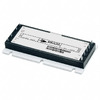
VI-2NK-CW-F1 Image
Image may be representation.
See specifications for product details.
EXPRESS OPTION
Payment method

VI-2NK-CW-F1 - Vicor Corporation

Manufacturer Part Number
VI-2NK-CW-F1
Manufacturer
Vicor
Allelco Part Number
98D-VI-2NK-CW-F1
Warranty
1 Year Allelco Warranty - Find out more
Stock Status:
42,908 pcs available, New & Original
Parts Description
DC DC CONVERTER 40V 100W
Package
Full Brick
Data sheet
VI-2NK-CW-F1.pdf

Environmental Information

Vicor REACH.pdf
RoHs Status
 
Our certification
In stock: 42908

Required fields are indicated by an asterisk (*)
Please send RFQ, we will respond immediately.

Quantity

Specifications

VI-2NK-CW-F1 Tech Specifications
Vicor Corporation - VI-2NK-CW-F1 technical specifications, attributes, parameters and parts with similar specifications to Vicor Corporation - VI-2NK-CW-F1

Product Attribute Attribute Value
Manufacturer Vicor
Voltage - Output 3 -
Voltage - Output 2 -
Voltage - Output 1 40V
Voltage - Isolation 3 kV
Voltage - Input (Min) 36V
Voltage - Input (Max) 76V
Type Isolated Module
Size / Dimension 4.60' L x 1.86' W x 0.79' H (116.8mm x 47.2mm x 20.1mm)
Series VI-200™ (100W)
Power (Watts) 100 W
Product Attribute Attribute Value
Package / Case Full Brick
Package Bulk
Operating Temperature -25°C ~ 85°C
Number of Outputs 1
Mounting Type Through Hole
Features OCP, OTP, OVP, SCP
Efficiency 90%
Current - Output (Max) 2.5A
Base Product Number VI-2NK
Applications ITE (Commercial)

Environmental & Export Classifications

ATTRIBUTE DESCRIPTION
RoHs Status RoHS non-compliant
Moisture Sensitivity Level (MSL) Not Applicable
REACH Status REACH Unaffected
ECCN EAR99
HTSUS 8504.40.9580

Frequently Asked Questions(FAQ)

How does the VI-2NK-CW-F1 compare to other 100W isolated DC-DC converters in terms of input voltage range and efficiency under typical industrial load conditions?
The VI-2NK-CW-F1 offers a relatively narrow input voltage range of 36V to 76V, which is narrower than some competitors supporting up to 100V or higher. While its 90% efficiency is competitive within the 100W class, it may fall short of newer high-efficiency models that achieve over 94% under light-to-medium loads. This makes it suitable for applications where input regulation is tightly controlled, but less ideal for systems with wide input fluctuations unless compensated by upstream regulation.
What are the thermal implications of operating the VI-2NK-CW-F1 at full 100W output in an uncontrolled ambient environment?
At continuous full load, the VI-2NK-CW-F1 dissipates approximately 11.1W as heat due to its 90% efficiency. In a natural convection environment without forced airflow, this can cause significant temperature rise—potentially exceeding 40°C above ambient—depending on board layout and thermal interface quality. Engineers must ensure adequate spacing and heat sinking to maintain junction temperatures below 85°C, especially near the upper end of the operating temperature range.
Can the VI-2NK-CW-CW-F1 be used reliably in telecom infrastructure applications requiring redundancy or hot-swap capability?
Yes, the VI-2NK-CW-F1 supports hot-swap functionality due to its soft-start and inrush current limiting features, making it compatible with telecom systems where power modules are replaced during operation. However, the lack of built-in remote sensing or margining means system-level monitoring must be implemented externally. Its isolation rating of 3 kV meets standard telecom safety requirements, though compliance with specific regional certifications like GR-1089 should be verified independently.
How does the VI-2NK-CW-F1 perform when subjected to rapid input voltage transients common in automotive or industrial environments?
The converter includes overvoltage protection (OVP) that activates above 76V, but transient response depends heavily on the input filter design. Without additional bulk capacitance or transient suppressors, large step changes (e.g., 76V to 100V spikes) may trigger OVP shutdown before the module recovers. For harsh environments, engineers should pair the VI-2NK-CW-F1 with input TVS diodes and sufficient hold-up capacitance to avoid nuisance tripping.
Is it feasible to parallel two VI-2NK-CW-F1 units to increase output current beyond 2.5A for higher-power loads?
No, the VI-2NK-CW-F1 does not support active current sharing natively. Parallel operation would require external circuitry such as droop control or master-slave configuration with dedicated communication lines, increasing complexity and risk of imbalance. Given the module’s fixed output impedance and lack of inter-module synchronization, paralleling is generally not recommended unless validated through extensive testing and derating strategies are applied.
What isolation considerations should be evaluated when integrating the VI-2NK-CW-F1 into a multi-board system with mixed-signal domains?
With a reinforced isolation voltage of 3 kV between input and output, the VI-2NK-CW-F1 satisfies most commercial ITE safety standards. However, creepage and clearance distances on the PCB must still comply with relevant codes (e.g., UL 62368). Careful layout is essential to prevent unintended coupling paths, especially if the output side interfaces with sensitive analog circuits. Ground planes should be split appropriately, and signal traces crossing isolation barriers must use opto-isolators or digital isolators instead of relying solely on power isolation.
How does the efficiency curve of the VI-2NK-CW-F1 behave across varying load percentages, and what impact does this have on system-level energy consumption?
The VI-2NK-CW-F1 maintains approximately 90% efficiency from 50% to 100% load, but drops noticeably below 30% load—common in standby modes. In a typical telecom base station that spends 60% of time at light load, total system efficiency can be reduced by 3–5 percentage points compared to a more efficient converter optimized for partial loads. This underscores the importance of selecting a converter aligned with actual duty cycle profiles.
Are there any known reliability concerns or failure modes associated with long-term use of the VI-2NK-CW-F1 in high-humidity environments?
The module is rated for -25°C to +85°C operation and includes overtemperature protection, but its RoHS non-compliant status suggests potential use of lead-based solder or other restricted materials. In high-humidity settings without conformal coating, moisture ingress could accelerate corrosion of internal components over decades of operation. While not inherently prone to failure, environmental sealing or protective coatings are advisable for extended reliability in damp climates.
What modifications or enhancements might improve the transient response of the VI-2NK-CW-F1 when driving capacitive or inductive loads?
Adding a small series inductance (e.g., 1–5 µH) at the output can dampen ringing caused by fast load steps, while a low-ESR ceramic capacitor bank (≥100 µF total) improves stability under dynamic loads. However, excessive capacitance (>1 mF) may degrade startup performance due to inrush current limitations. These adjustments should be validated against Vicor’s application notes, as they may affect fault detection thresholds like overcurrent protection.
How does the physical footprint and mounting style of the VI-2NK-CW-F1 influence placement decisions in space-constrained designs?
At 116.8 x 47.2 mm, the full brick form factor occupies significant board area. Its through-hole mounting requires plated-through holes and robust mechanical anchoring, which may limit flexibility in high-vibration environments without additional retention hardware. Alternatives like half-brick or quarter-brick modules offer similar power density in smaller packages, but only if the system architecture allows for modular power distribution.
What are the implications of using the VI-2NK-CW-F1 in a system requiring galvanic isolation between multiple DC buses?
Since the VI-2NK-CW-F1 provides only single-ended input to single-ended output isolation, it cannot directly isolate bidirectional or dual-polarity bus architectures. To implement multi-bus isolation, each bus would need dedicated modules or a central isolation stage preceding the VI-2NK-CW-F1. This increases cost and complexity, making it less efficient than integrated multi-output isolated solutions for distributed power systems.
Does the VI-2NK-CW-F1 support remote enable/disable functionality, and how does this affect fault recovery behavior?
Yes, the VI-2NK-CW-F1 accepts a logic-level signal on the ENABLE pin to gate operation. When disabled, it draws minimal quiescent current (<1 mA), enabling low-power standby states. Upon re-enabling, the module performs a controlled soft-start sequence, preventing surge currents during restart after faults. This feature aids in system-level power sequencing and fault containment but requires coordination with downstream loads to avoid brownout conditions.
How does the VI-2NK-CW-F1 compare to modern digital power converters like those using PMBus in terms of configurability and diagnostics?
Unlike programmable digital converters with serial interfaces, the VI-2NK-CW-F1 operates in closed-loop mode with fixed parameters. It lacks telemetry reporting, margining, or firmware updates, limiting real-time optimization. For applications demanding adaptive control or predictive maintenance, newer PMBus-compatible modules may offer better long-term value despite potentially lower peak efficiency. The choice hinges on whether configurability outweighs raw performance in the target system lifecycle.
What precautions should be taken when soldering the VI-2NK-CW-F1 onto a production PCB to avoid damage during assembly?
Due to its metal base and high thermal mass, the VI-2NK-CW-F1 requires careful thermal management during reflow. Excessive dwell time above 260°C or peak temperatures exceeding 280°C can compromise solder joints or internal bonds. Hand soldering is not recommended; automated wave soldering with pre-heat staging minimizes stress. Always follow IPC Class 3 guidelines for high-reliability assemblies, including proper flux selection and cleaning post-assembly.
Can the VI-2NK-CW-F1 be safely used in medical equipment applications requiring enhanced insulation and patient leakage current limits?
The VI-2NK-CW-F1 meets basic isolation requirements but is not designed for medical-grade safety standards (e.g., IEC 60601). Its 3 kV isolation and component selection do not guarantee compliance with stringent patient leakage limits or reinforced insulation needed in Class II medical devices. Additional external isolation stages and certified enclosure designs would be required, making direct substitution risky without full regulatory review.
What role does the MSL classification play in handling and storage of the VI-2NK-CW-F1, and why is it listed as "Not Applicable"?
The MSL rating of "Not Applicable" indicates the VI-2NK-CW-F1 is a fully assembled, non-component module rather than discrete semiconductor. As such, it is not subject to moisture-induced delamination risks during reflow, eliminating the need for humidity preconditioning. This simplifies supply chain logistics but means users must handle it as a finished unit with standard ESD precautions during installation.

Parts with Similar Specifications

The three parts on the right have similar specifications to Vicor Corporation VI-2NK-CW-F1

Product Attribute VI-2NK-CW-F4 VI-2NK-CV-F1 VI-2NK-CW-F2 VI-2NK-CW-F3
Part Number VI-2NK-CW-F4 VI-2NK-CV-F1 VI-2NK-CW-F2 VI-2NK-CW-F3
Manufacturer Vicor Corporation Vicor Corporation Vicor Corporation Vicor Corporation
Series - - - -
Current - Output (Max) - - - -
Features - - - Simultaneous Sampling
Voltage - Input (Min) - - - -
Base Product Number - DAC34H84 MAX500 ADS62P42
Number of Outputs - - - -
Type - - - -
Voltage - Input (Max) - - - -
Applications - - - -
Size / Dimension - - - -
Package / Case - 196-LFBGA 16-DIP (0.300', 7.62mm) 64-VFQFN Exposed Pad
Voltage - Output 2 - - - -
Voltage - Output 3 - - - -
Package - Tape & Reel (TR) Tube Tape & Reel (TR)
Efficiency - - - -
Operating Temperature - -40°C ~ 85°C 0°C ~ 70°C -40°C ~ 85°C
Voltage - Output 1 - - - -
Power (Watts) - - - -
Voltage - Isolation - - - -
Mounting Type - Surface Mount Through Hole Surface Mount

VI-2NK-CW-F1 Datasheet PDF

Download VI-2NK-CW-F1 pdf datasheets and Vicor Corporation documentation for VI-2NK-CW-F1 - Vicor Corporation.

Datasheets
VI/VE-200 Family.pdf
Design Resources
VI-200, VI-J00 Design Guide, Appl Manual.pdf
Environmental Information
Vicor REACH.pdf

Customer Reviews

Evaluation: 10 Articles

  • ECUb***h
    Sep 22, 2026

    Used for repair of an older automotive ECU. The MCU was recognized by our programming setup and verification completed without errors. The repaired board now starts and communicates normally.

  • RS48***ieldTech
    Sep 16, 2026

    Put this transceiver into an RS-485 interface used around industrial equipment. Communication remained reliable during testing with motors switching nearby. Good result for the replacement board.

  • Logi***b_Chris
    Sep 8, 2026

    Purchased for a Cyclone III development project. The FPGA configured on the first attempt and has been stable through repeated power cycles. No problems with the I/O we are using.

  • Circ***FixerTom
    Sep 2, 2026

    Used this rectifier in a high-current power supply repair. Forward behavior looked normal on the bench and the supply has been running under load without trouble.

  • Retr***UWorks
    Aug 31, 2026

    Needed the exact ST10F269Z2Q6 for servicing an older control unit. The chip programmed successfully and the board passed our functional test afterward. Much easier than redesigning around a newer MCU.

  • Andr***PCBLab
    Aug 28, 2026

    I needed this ADC for an older data acquisition board. Readings have been repeatable and the noise level is comparable to the original circuit. Happy with the purchase.

  • Leat***O'Keefe
    Aug 20, 2026

    one of my hobbies is skydiving. and when i'm skydiving this works great.

  • Ilen***
    Aug 20, 2026

    This product works considerably well. It secretly improves my basketball by a lot.

  • Indu***ialPower
    Aug 17, 2026

    Installed this IGBT module in a power conversion cabinet. Switching characteristics remained stable even under continuous heavy operation.

  • Nikh***ech
    Aug 13, 2026

    Great low-power MCU for portable equipment. Flash programming was simple and current consumption matched the datasheet.

Write a Review

Your Email address will not be published.

Shipment

Delivery Time

In-stock items can be shipped within 24 hours. Some parts will be arranged for delivery within 1-2 days from the date all items arrive at our warehouse. And Allelco ships order once a day at about 17:00, except Sunday. Once the goods are shipped, the estimated delivery time depends on the shipping methods and Delivery destination. The table below shows are the logistic time for some common countries.

Delivery Cost

  1. Use your express account for shipment if you have one.
  2. Use our account for the shipment. Refer to the table below for the approximate charges.
(Different time frame / countries / package size has different price.)

Delivery Method

  1. Global Common Shipment by DHL / UPS / FedEx / TNT / EMS / SF we support.
  2. Others more shipping ways, please get in touch with your customer manager.

Common Countries Logistic Time Reference
Region Country Logistic Time(Day)
America United States 5
Brazil 7
Europe Germany 5
United Kingdom 4
Italy 5
Oceania Australia 6
New Zealand 5
Asia India 4
Japan 4
Middle East Israel 6
DHL & FedEx Shipment Charges Reference
Shipment charges(KG) Reference DHL(USD$)
0.00kg-1.00kg USD$30.00 - USD$60.00
1.00kg-2.00kg USD$40.00 - USD$80.00
2.00kg-3.00kg USD$50.00 - USD$100.00
Note:
The above table is for reference only. There may have some data bias for the uncontrollable factors.
Contact us if you have any questions.
  • QC (Quality Warranty)
  • Payment Support
  • Packaging
  • Certifications & Memberships

QC (Quality Warranty)

Allelco is committed to exceeding customer expectations through customer service excellence, order accuracy, and on-time delivery.
This is achieved through our commitment to the continual improvement of our processes, services, and products.


Strict quality inspection builds a solid foundation for electronic component quality.
  1. Visual inspection
  2. Performance testing and reliability verification
  3. Standardized full-process testing
  4. Precise control of every parameter
We eliminate defective components and ensure the stable operation of electronic devices through professional quality standards.

Payment Support

The payment method can be chosen from the methods shown below: Wire Transfer (T/T, Bank Transfer), Western Union, Credit card, PayPal.
  • HKBea
  • Paypal
  • MasterCard
  • Western-Union
  • VISA
Stable Delivery, Sincere Partnership — Your Faithful Supply Chain Partner
  • Efficient Supply Management
  • Cost-Saving Procurement
  • Fast Sourcing & Delivery
Contact us if you have any questions.

Packaging

Electrostatic Discharge Protection and Handling

All electrostatic-sensitive components are handled in accordance with electrostatic discharge control procedures. The products are hermetically sealed in anti-static safe packaging to prevent electrostatic damage. Appropriate labeling is also applied for identification and traceability. This ensures product integrity during storage, handling and transportation.


ESD

Certifications & Memberships

Third-party certified, strict quality control. Our certification
  • ISO 9001: 2015
  • ISO 13485: 2016
  • ISO 14001: 2015
  • ISO 28000: 2007
  • ISO 45001: 2018
  • GB/T 27922-2011
  • SMTA
  • IPC
  • ESD
  • PSMA
VI-2NK-CW-F1 Image

VI-2NK-CW-F1

Vicor Corporation
98D-VI-2NK-CW-F1

Want a better price? Add to Cart and Submit RFQ now, we'll contact you immediately.

0 RFQ
Shopping cart (0 Items)
It is empty.
Compare List (0 Items)
It is empty.
Feedback

Your feedback matters! At Allelco, we value the user experience and strive to improve it constantly.
Please share your comments with us via our feedback form, and we'll respond promptly.
Thank you for choosing Allelco.

Subject
E-mail
Comments
Captcha
Drag or click to upload file
Upload File
types: .xls, .xlsx, .doc, .docx, .jpg, .png and .pdf.
Max file size: 10MB