View All

Please refer to the English Version as our Official Version.Return

Europe
France(Français) Germany(Deutsch) Italy(Italia) Russian(русский) Poland(polski) Czech(Čeština) Luxembourg(Lëtzebuergesch) Netherlands(Nederland) Iceland(íslenska) Hungarian(Magyarország) Spain(español) Portugal(Português) Turkey(Türk dili) Bulgaria(Български език) Ukraine(Україна) Greece(Ελλάδα) Israel(עִבְרִית) Sweden(Svenska) Finland(Svenska) Finland(Suomi) Romania(românesc) Moldova(românesc) Slovakia(Slovenská) Denmark(Dansk) Slovenia(Slovenija) Slovenia(Hrvatska) Croatia(Hrvatska) Serbia(Hrvatska) Montenegro(Hrvatska) Bosnia and Herzegovina(Hrvatska) Lithuania(lietuvių) Spain(Português) Switzerland(Deutsch) United Kingdom(English)
Asia/Pacific
Japan(日本語) Korea(한국의) Thailand(ภาษาไทย) Malaysia(Melayu) Singapore(Melayu) Vietnam(Tiếng Việt) Philippines(Pilipino)
Africa, India and Middle East
United Arab Emirates(العربية) Iran(فارسی) Tajikistan(فارسی) India(हिंदी) Madagascar(malaɡasʲ)
South America / Oceania
New Zealand(Maori) Brazil(Português) Angola(Português) Mozambique(Português)
North America
United States(English) Canada(English) Haiti(Ayiti) Mexico(español)
HomeProductsPower Supplies - (Board Mount)DC DC ConvertersVI-2NK-CW-F3
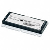
VI-2NK-CW-F3 Image
Image may be representation.
See specifications for product details.
EXPRESS OPTION
Payment method

VI-2NK-CW-F3 - Vicor Corporation

Manufacturer Part Number
VI-2NK-CW-F3
Manufacturer
Vicor
Allelco Part Number
98D-VI-2NK-CW-F3
Warranty
1 Year Allelco Warranty - Find out more
Stock Status:
47,320 pcs available, New & Original
Parts Description
DC DC CONVERTER 40V 100W
Package
Full Brick
Data sheet
VI-2NK-CW-F3.pdf

Environmental Information

Vicor REACH.pdf
RoHs Status
 
Our certification
In stock: 47320

Required fields are indicated by an asterisk (*)
Please send RFQ, we will respond immediately.

Quantity

Specifications

VI-2NK-CW-F3 Tech Specifications
Vicor Corporation - VI-2NK-CW-F3 technical specifications, attributes, parameters and parts with similar specifications to Vicor Corporation - VI-2NK-CW-F3

Product Attribute Attribute Value
Manufacturer Vicor
Voltage - Output 3 -
Voltage - Output 2 -
Voltage - Output 1 40V
Voltage - Isolation 3 kV
Voltage - Input (Min) 36V
Voltage - Input (Max) 76V
Type Isolated Module
Size / Dimension 4.60' L x 1.86' W x 0.79' H (116.8mm x 47.2mm x 20.1mm)
Series VI-200™ (100W)
Power (Watts) 100 W
Product Attribute Attribute Value
Package / Case Full Brick
Package Bulk
Operating Temperature -25°C ~ 85°C
Number of Outputs 1
Mounting Type Through Hole
Features OCP, OTP, OVP, SCP
Efficiency 90%
Current - Output (Max) 2.5A
Base Product Number VI-2NK
Applications ITE (Commercial)

Environmental & Export Classifications

ATTRIBUTE DESCRIPTION
RoHs Status RoHS non-compliant
Moisture Sensitivity Level (MSL) Not Applicable
REACH Status REACH Unaffected
ECCN EAR99
HTSUS 8504.40.9580

Frequently Asked Questions(FAQ)

How does the VI-2NK-CW-F3 compare to other 100W isolated DC-DC converters in terms of input voltage range and efficiency, and what are the implications for system-level power architecture design?
The VI-2NK-CW-F3 operates across a 36V to 76V input window, which aligns with typical 48V telecom and industrial bus standards, allowing it to interface directly with high-voltage rails without additional front-end regulation. With an efficiency of 90%, it outperforms many legacy brick converters in this power class, particularly those based on older synchronous rectification techniques or lower switching frequencies. This efficiency advantage translates into reduced thermal management requirements and lower conduction losses at full load. When evaluating alternatives, converters with narrower input ranges may necessitate additional bulk capacitance or pre-regulators to handle transients, whereas the VI-2NK-CW-F3 supports stable operation over a broader dynamic range. Designers must consider whether the wider input tolerance provides sufficient margin for their specific application’s line variation or fault conditions.
What is the significance of the VI-2NK-CW-F3 having a 3 kV isolation rating, and how does this affect safety compliance and fault isolation in commercial ITE equipment?
The 3 kV isolation voltage between input and output meets stringent safety standards such as UL 62368-1 for Information Technology Equipment, ensuring personnel protection during maintenance and operation. In systems where multiple power domains share a common chassis, this galvanic isolation prevents ground loops and limits fault currents that could propagate from one section to another. For the VI-2NK-CW-F3, the isolation barrier supports safe use in non-isolated primary power systems by decoupling downstream circuits while maintaining regulatory approval. However, because RoHS status is listed as non-compliant, designers must verify end-of-life disposal protocols and assess substitution risks if environmental regulations tighten further.
Given the VI-2NK-CW-F3's maximum output current of 2.5A at 40V, what derating considerations should be applied when operating at elevated ambient temperatures?
The device is rated for -25°C to 85°C, but continuous full-power operation above 60°C typically requires derating due to semiconductor junction temperature limits and long-term reliability concerns. Assuming natural convection cooling, thermal resistance from case to ambient may exceed 3°C/W; thus, 100W output would raise the case temperature by approximately 30°C above ambient. At 85°C ambient, internal components may approach their thermal thresholds, potentially triggering overtemperature protection (OTP) or reducing lifetime via accelerated electromigration. Engineers should consult Vicor’s thermal modeling tools or perform empirical testing under worst-case airflow to validate sustained performance.
Why might someone choose the VI-2NK-CW-F3 over a non-isolated converter despite the added complexity and cost, especially in a commercial lighting or motor control application?
Isolation is critical in applications where human contact with exposed conductors poses a risk, such as LED drivers or industrial sensors powered through long cables. The VI-2NK-CW-F3 provides inherent protection against electric shock by separating primary and secondary circuits, enabling compliance with IEC 61140 and similar safety norms. Non-isolated solutions may save space and cost but require extensive creepage and clearance planning and cannot tolerate single-fault conditions like insulation breakdown. Furthermore, in noisy environments, the VI-2NK-CW-F3 suppresses common-mode noise propagation, improving signal integrity in analog subsystems fed from its 40V rail.
How does the Full Brick footprint of the VI-2NK-CW-F3 influence PCB layout constraints compared to smaller form factors like quarter-brick or half-brick modules?
The VI-2NK-CW-F3 measures 116.8mm x 47.2mm x 20.1mm, representing a traditional Full Brick format. While this enables high power density within standardized mounting patterns, it consumes more board real estate than smaller formats—potentially limiting scalability in compact designs. Layout engineers must allocate space for thermal vias beneath the module, maintain minimum spacing from high-current traces to avoid coupling losses, and ensure adequate airflow or heatsinking. However, its through-hole mounting offers mechanical robustness and ease of retrofitting into existing enclosures. Smaller bricks may offer better integration in space-constrained systems but often sacrifice peak power or input range flexibility.
Can the VI-2NK-CW-F3 support remote ON/OFF functionality, and how does this feature integrate into system monitoring and fault reporting?
Yes, the VI-2NK-CW-F3 includes standard enable (EN) pin functionality, allowing remote shutdown via a logic-level control signal. This enables centralized power sequencing across multiple modules in redundant architectures or facilitates brown-out detection by disabling conversion before undervoltage damage occurs. When combined with built-in protections—overcurrent (OCP), overvoltage (OVP), overtemperature (OTP), and short-circuit (SCP)—the module supports intelligent fault response without microcontroller intervention. Designers can monitor status pins or use supervisory ICs to log faults and trigger alarms in industrial automation setups.
What are the key trade-offs when selecting the VI-2NK-CW-F3 versus a custom-designed isolated forward converter for a 100W 40V output stage?
The VI-2NK-CW-F3 reduces development time and verification effort by delivering a tested, certified solution with integrated magnetics and control circuitry. Custom designs may achieve marginally higher efficiency or tighter regulation under variable loads but require extensive EMI testing, safety agency approvals, and qualification cycles. For low-to-medium volume production, using the VI-2NK-CW-F3 avoids NRE costs and accelerates time-to-market. However, at very high volumes or extreme environmental demands (e.g., automotive), a custom topology might optimize BOM cost or size. The VI-2NK-CW-F3 remains advantageous when leveraging Vicor’s proven reliability data and global supply chain resilience.
How does the VI-2NK-CW-F3’s efficiency profile behave under light-load conditions, and what impact does this have on standby power consumption in battery-backed or energy-harvesting systems?
Datasheets typically specify 90% efficiency at full load, but efficiency drops at light loads due to fixed switching losses and quiescent current draw. Without detailed light-load curves, conservative estimates suggest efficiency falls below 70% below 10% load, increasing wasted energy in idle states. In battery-powered applications where the VI-2NK-CW-F3 powers always-on sensors, this inefficiency raises self-discharge rates and reduces runtime. Adding external shutdown control or using a low-power mode (if supported) mitigates this, but designers should evaluate whether the module’s fixed-frequency architecture aligns with strict energy harvesting requirements.
Why is the VI-2NK-CW-F3 classified under ECCN EAR99 and HTSUS 8504.40.9580, and what does this imply for international sourcing and export compliance?
ECCN EAR99 indicates the VI-2NK-CW-F3 is not subject to strict U.S. export controls, making it readily available from most distributors worldwide. HTSUS 8504.40.9580 categorizes it as a “static converters” under customs tariff schedules, typically resulting in moderate import duties in countries following WCO classifications. This classification simplifies logistics for commercial ITE applications but requires accurate documentation to avoid delays. Because it lacks cryptographic or military-grade enhancements, it does not fall under ITAR or dual-use restrictions, facilitating global deployment in non-sensitive infrastructure.
What precautions are necessary when integrating the VI-2NK-CW-F3 into a system requiring tight output voltage tolerance (±2%) for precision instrumentation?
The VI-2NK-CW-F3 has specified load and line regulation figures, but absolute accuracy depends on feedback loop stability and component tolerances. To meet ±2% requirements, designers may need to add post-regulation with LDOs or digital compensation networks. Additionally, PCB parasitics, trace impedance, and grounding strategy significantly affect output ripple and transient response. A four-wire Kelvin connection from the module’s sense pins can improve regulation over long wires. Without onboard filtering, high-frequency noise from switching edges may violate sensitivity thresholds in measurement circuits, necessitating careful layout and shielding.
How does moisture sensitivity level (MSL) being “Not Applicable” for the VI-2NK-CW-F3 influence handling procedures during reflow soldering or hand assembly?
Since the VI-2NK-CW-F3 uses through-hole leads and a robust ceramic substrate, it is not susceptible to moisture-induced popcorning during thermal cycling. This eliminates the need for baking prior to soldering and allows standard wave-soldering processes without special precautions. Hand soldering is also less risky compared to surface-mount devices requiring IR reflow. Assembly teams can proceed with conventional flux application and solder profiling, reducing process complexity and potential defects related to humidity exposure.
What role do the OCP, OTP, OVP, and SCP features play in protecting downstream loads connected to the VI-2NK-CW-F3, and how do they interact during fault recovery?
Overcurrent protection (OCP) detects excessive draw and limits current to prevent damage to the converter itself and connected electronics. Overtemperature (OTP) shuts down the unit if internal junctions exceed safe thresholds, while overvoltage (OVP) clamps output spikes caused by transients or control faults. Short-circuit protection (SCP) acts as a last-resort defense during catastrophic failure modes. These protections are typically latching or auto-retry based on implementation; understanding reset behavior is essential for system-level diagnostics. For example, repeated OTP events during startup may indicate inadequate heatsinking, prompting redesign rather than just load adjustment.
How does the VI-2NK-CW-F3’s base product number VI-2NK relate to other variants in the VI-200™ series, and what selection criteria differentiate them?
The VI-2NK-CW-F3 belongs to the VI-200™ family, sharing core architecture and pinout with variants like VI-2NK-AW-F3 or VI-2NK-DW-F3. Differences typically include input/output voltage ratings, efficiency curves, or packaging options. Choosing among them involves matching input range compatibility, output precision needs, and thermal profiles. The “CW” suffix likely denotes conformal coating or extended temperature capability, though exact specifications require cross-referencing datasheets. Designers should prioritize variants with matching isolation voltage and certification alignment for their target market to avoid re-qualification efforts.
In what scenarios would the VI-2NK-CW-F3 be unsuitable despite its high efficiency and wide input range, and what alternative topologies might better serve those cases?
The VI-2NK-CW-F3 may be impractical in ultra-compact, low-cost consumer products where size and price dominate, as Full Brick modules carry a premium. Similarly, if bidirectional power flow or regenerative braking is required, standard unidirectional converters like this one won’t suffice. Applications demanding fractional horsepower motors or linear regulators may prefer lower-power, fully integrated solutions. Additionally, if the system operates primarily at inputs below 36V or above 76V, a buck-boost or SEPIC-based design could extend operational range more efficiently. Always validate against total cost of ownership, including cooling, enclosure size, and lifecycle support.
How does the VI-2NK-CW-F3’s efficiency of 90% translate into actual heat dissipation under continuous full-load operation, and what cooling strategy is minimally acceptable?
At 100W output and 90% efficiency, input power is approximately 111W, resulting in 11W of power dissipated as heat. If the module’s thermal resistance from case to ambient is 3°C/W, then under still air, the case temperature rises by ~33°C above ambient. At 85°C ambient, the junction temperature could approach 120–130°C, nearing silicon limits. Therefore, passive cooling may only be acceptable near upper ambient limits or with enhanced airflow. Mounting to a metal chassis via standoffs or applying thermal interface material improves heat spreading and extends reliability margins.
Can the VI-2NK-CW-F3 operate in parallel with another identical unit for redundancy or increased current sharing, and what challenges arise?
Parallel operation is generally not recommended without active current-sharing circuitry unless the manufacturer explicitly supports it. The VI-2NK-CW-F3 lacks built-in droop or master-slave signaling, leading to unequal current distribution due to slight parameter mismatches. One module may dominate load while the other remains underutilized or thermally stressed. For redundancy, hot-swappable designs with OR-ing diodes or electronic switches are safer. True paralleling requires external balancing resistors or digital control interfaces not present in this model.
How does the REACH status of “Unaffected” for the VI-2NK-CW-F3 simplify material compliance tracking in EU-based manufacturing?
“REACH Unaffected” means the VI-2NK-CW-F3 contains no substances of very high concern (SVHCs) exceeding 0.1% weight, eliminating the need for SCIP database notifications or supplier declarations under EU Regulation 1907/2006. This reduces administrative overhead and audit complexity for OEMs shipping equipment into Europe. However, RoHS non-compliance implies lead content or certain restricted materials may still be present, necessitating careful review of exemption clauses (e.g., Pb in solders or ceramics) and alignment with national implementations.
What diagnostic information is accessible during operation of the VI-2NK-CW-F3, and how can engineers leverage it for predictive maintenance?
The VI-2NK-CW-F3 provides limited status signals such as enable/disable and fault indication pins, but lacks telemetry outputs like temperature sensing or cycle counting. Engineers can infer health from output stability, audible noise, or thermal behavior. Monitoring startup timing and fault latch states helps detect aging capacitors or degraded insulation. For advanced diagnostics, pairing the module with external shunts or infrared thermography adds value. Without embedded intelligence, predictive maintenance relies on historical failure rates from field data rather than real-time analytics.

Parts with Similar Specifications

The three parts on the right have similar specifications to Vicor Corporation VI-2NK-CW-F3

Product Attribute VI-2NK-CW-F2 VI-2NK-CW-F1 VI-2NK-CW-F4 VI-2NK-CV-F3
Part Number VI-2NK-CW-F2 VI-2NK-CW-F1 VI-2NK-CW-F4 VI-2NK-CV-F3
Manufacturer Vicor Corporation Vicor Corporation Vicor Corporation Vicor Corporation
Voltage - Output 2 - - - -
Package / Case - 196-LFBGA 16-DIP (0.300', 7.62mm) 64-VFQFN Exposed Pad
Type - - - -
Mounting Type - Surface Mount Through Hole Surface Mount
Package - Tape & Reel (TR) Tube Tape & Reel (TR)
Series - - - -
Number of Outputs - - - -
Operating Temperature - -40°C ~ 85°C 0°C ~ 70°C -40°C ~ 85°C
Applications - - - -
Voltage - Input (Max) - - - -
Voltage - Input (Min) - - - -
Features - - - Simultaneous Sampling
Voltage - Output 3 - - - -
Size / Dimension - - - -
Voltage - Isolation - - - -
Base Product Number - DAC34H84 MAX500 ADS62P42
Current - Output (Max) - - - -
Efficiency - - - -
Power (Watts) - - - -
Voltage - Output 1 - - - -

VI-2NK-CW-F3 Datasheet PDF

Download VI-2NK-CW-F3 pdf datasheets and Vicor Corporation documentation for VI-2NK-CW-F3 - Vicor Corporation.

Datasheets
VI/VE-200 Family.pdf
Design Resources
VI-200, VI-J00 Design Guide, Appl Manual.pdf
Environmental Information
Vicor REACH.pdf

Customer Reviews

Evaluation: 10 Articles

  • ECUb***h
    Sep 22, 2026

    Used for repair of an older automotive ECU. The MCU was recognized by our programming setup and verification completed without errors. The repaired board now starts and communicates normally.

  • RS48***ieldTech
    Sep 16, 2026

    Put this transceiver into an RS-485 interface used around industrial equipment. Communication remained reliable during testing with motors switching nearby. Good result for the replacement board.

  • Logi***b_Chris
    Sep 8, 2026

    Purchased for a Cyclone III development project. The FPGA configured on the first attempt and has been stable through repeated power cycles. No problems with the I/O we are using.

  • Circ***FixerTom
    Sep 2, 2026

    Used this rectifier in a high-current power supply repair. Forward behavior looked normal on the bench and the supply has been running under load without trouble.

  • Retr***UWorks
    Aug 31, 2026

    Needed the exact ST10F269Z2Q6 for servicing an older control unit. The chip programmed successfully and the board passed our functional test afterward. Much easier than redesigning around a newer MCU.

  • Andr***PCBLab
    Aug 28, 2026

    I needed this ADC for an older data acquisition board. Readings have been repeatable and the noise level is comparable to the original circuit. Happy with the purchase.

  • Leat***O'Keefe
    Aug 20, 2026

    one of my hobbies is skydiving. and when i'm skydiving this works great.

  • Ilen***
    Aug 20, 2026

    This product works considerably well. It secretly improves my basketball by a lot.

  • Indu***ialPower
    Aug 17, 2026

    Installed this IGBT module in a power conversion cabinet. Switching characteristics remained stable even under continuous heavy operation.

  • Nikh***ech
    Aug 13, 2026

    Great low-power MCU for portable equipment. Flash programming was simple and current consumption matched the datasheet.

Write a Review

Your Email address will not be published.

Shipment

Delivery Time

In-stock items can be shipped within 24 hours. Some parts will be arranged for delivery within 1-2 days from the date all items arrive at our warehouse. And Allelco ships order once a day at about 17:00, except Sunday. Once the goods are shipped, the estimated delivery time depends on the shipping methods and Delivery destination. The table below shows are the logistic time for some common countries.

Delivery Cost

  1. Use your express account for shipment if you have one.
  2. Use our account for the shipment. Refer to the table below for the approximate charges.
(Different time frame / countries / package size has different price.)

Delivery Method

  1. Global Common Shipment by DHL / UPS / FedEx / TNT / EMS / SF we support.
  2. Others more shipping ways, please get in touch with your customer manager.

Common Countries Logistic Time Reference
Region Country Logistic Time(Day)
America United States 5
Brazil 7
Europe Germany 5
United Kingdom 4
Italy 5
Oceania Australia 6
New Zealand 5
Asia India 4
Japan 4
Middle East Israel 6
DHL & FedEx Shipment Charges Reference
Shipment charges(KG) Reference DHL(USD$)
0.00kg-1.00kg USD$30.00 - USD$60.00
1.00kg-2.00kg USD$40.00 - USD$80.00
2.00kg-3.00kg USD$50.00 - USD$100.00
Note:
The above table is for reference only. There may have some data bias for the uncontrollable factors.
Contact us if you have any questions.
  • QC (Quality Warranty)
  • Payment Support
  • Packaging
  • Certifications & Memberships

QC (Quality Warranty)

Allelco is committed to exceeding customer expectations through customer service excellence, order accuracy, and on-time delivery.
This is achieved through our commitment to the continual improvement of our processes, services, and products.


Strict quality inspection builds a solid foundation for electronic component quality.
  1. Visual inspection
  2. Performance testing and reliability verification
  3. Standardized full-process testing
  4. Precise control of every parameter
We eliminate defective components and ensure the stable operation of electronic devices through professional quality standards.

Payment Support

The payment method can be chosen from the methods shown below: Wire Transfer (T/T, Bank Transfer), Western Union, Credit card, PayPal.
  • HKBea
  • Paypal
  • MasterCard
  • Western-Union
  • VISA
Stable Delivery, Sincere Partnership — Your Faithful Supply Chain Partner
  • Efficient Supply Management
  • Cost-Saving Procurement
  • Fast Sourcing & Delivery
Contact us if you have any questions.

Packaging

Electrostatic Discharge Protection and Handling

All electrostatic-sensitive components are handled in accordance with electrostatic discharge control procedures. The products are hermetically sealed in anti-static safe packaging to prevent electrostatic damage. Appropriate labeling is also applied for identification and traceability. This ensures product integrity during storage, handling and transportation.


ESD

Certifications & Memberships

Third-party certified, strict quality control. Our certification
  • ISO 9001: 2015
  • ISO 13485: 2016
  • ISO 14001: 2015
  • ISO 28000: 2007
  • ISO 45001: 2018
  • GB/T 27922-2011
  • SMTA
  • IPC
  • ESD
  • PSMA
VI-2NK-CW-F3 Image

VI-2NK-CW-F3

Vicor Corporation
98D-VI-2NK-CW-F3

Want a better price? Add to Cart and Submit RFQ now, we'll contact you immediately.

0 RFQ
Shopping cart (0 Items)
It is empty.
Compare List (0 Items)
It is empty.
Feedback

Your feedback matters! At Allelco, we value the user experience and strive to improve it constantly.
Please share your comments with us via our feedback form, and we'll respond promptly.
Thank you for choosing Allelco.

Subject
E-mail
Comments
Captcha
Drag or click to upload file
Upload File
types: .xls, .xlsx, .doc, .docx, .jpg, .png and .pdf.
Max file size: 10MB