7-Segment Display: Pin Configuration, Types and Operating Principle
This guide explains everything about seven-segment displays. It talks about how they work, the two main types (common anode and common cathode), and how the parts inside are arranged. You'll learn how to connect and control them using microcontrollers like Arduino, and how to make simple circuits with driver chips like the 4511. The guide also covers where these displays are used in life, their good points, and some things they can’t do.Catalog

Figure 1. Seven-Segment Display
What is a Seven-Segment Display?
A seven-segment display is an electronic component designed to show numbers and a few letters using seven light-emitting segments arranged in a figure-eight layout. Each segment, labeled A through G, lights up individually to form digits from 0 to 9. A small eighth segment, usually a dot in the bottom-right corner, can also be included to represent decimal points.
Each segment is an LED that emits light when powered. The display works by applying voltage across the LED’s terminals, which causes light to be produced through electroluminescence.
Seven-segment displays became popular in the 1960s and 70s as LEDs replaced earlier display technologies like Nixie tubes and mechanical indicators. These new displays were easier to drive, used less power, and were more durable. By the late '70s, they were standard in calculators, clocks, and measuring devices.
Even today, these displays are widely used in devices that need simple, reliable numeric output. They offer low power consumption, strong visibility, and straightforward control logic. Improved LED materials have also made them brighter and more durable, which helps maintain their role in both compact gadgets and large industrial systems.
Types of Seven-Segment Displays
Seven-segment displays come in two main types, based on how the internal LEDs are wired: common anode (CA) and common cathode (CC). The difference lies in how the LED segments share electrical connections.
Common Anode (CA)
In a common anode display, all the positive sides (called anodes) of the LEDs are connected together. This group of positive connections is linked to the positive power supply.
To turn on a segment (one part of the number display), you send a LOW signal (which means a connection to ground or 0 volts) to the negative side (called the cathode) of that segment. This allows electricity to flow and the segment lights up.
This type of display works well with certain types of digital circuits, especially ones that are designed to pull current down to ground. An example is TTL (Transistor-Transistor Logic) circuits.

Figure 2. Common Anode Configuration

Figure 3. Truth Table
Common Cathode (CC)
In a common cathode display, all the negative sides (cathodes) of the LEDs are connected together and tied to ground.
To light up a segment, you send a HIGH signal (a voltage, like 5V) to the positive side (anode) of that segment. This makes electricity flow from the positive pin through the LED to ground, and the segment lights up.
Common cathode displays are usually easier to use with microcontrollers, like Arduino or Raspberry Pi, because these devices can send out the needed HIGH signal directly from their output pins.

Figure 4. Common Cathode Configuration

Figure 5. Truth Table
Structure of a Seven-Segment Display

Figure 6. Top View of Seven Segment Display
Each seven-segment display digit consists of seven individual LEDs arranged in a rectangular pattern that resembles an "8". The segments are labeled A through G, with three horizontal segments (A, G, D) and four vertical ones (B, C, E, F). Some displays also include a decimal point, located near the bottom-right corner.

Figure 7. Decimal or Dot Point
Modern displays usually use surface-mounted LEDs embedded in plastic or resin. The display housing often includes light barriers to prevent glow from bleeding into neighboring segments. The casing is typically tinted or frosted to help diffuse the light and improve contrast.
Standard single-digit displays have ten pins: one for each of the seven segments, one for the decimal point, and one or two for the shared common terminal. Inside the case, thin wires or traces connect each segment to its respective pin.
Some displays include built-in resistors to control current, while others require external resistors. Good thermal design helps the display run reliably over long periods, even in challenging environments.
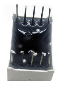
Figure 8. Bottom View of Seven Segment Display
Pin Configuration of a Seven-Segment Display

Figure 9. Pin Diagram
|
Pin Number |
Connected
Segment |
Function |
|
Pin 1 |
E |
Controls segment E |
|
Pin 2 |
D |
Controls segment D |
|
Pin 3 |
COM (Common Pin) |
Common Anode or Cathode |
|
Pin 4 |
C |
Controls segment C |
|
Pin 5 |
DP |
Controls Decimal Point (DP) |
|
Pin 6 |
B |
Controls segment B |
|
Pin 7 |
A |
Controls segment A |
|
Pin 8 |
COM (Common Pin) |
Common Anode or Cathode |
|
Pin 9 |
F |
Controls segment F |
|
Pin 10 |
G |
Controls segment G |
How Does a Seven-Segment Display Work?
A seven-segment display works by lighting specific segments to form numbers or simple letters. Each segment is an individual LED that glows when current flows through it in the correct direction.

Figure 10. Display Numbers
To show a number, the system turns on the correct combination of segments. For example, to display "0," all segments except G are lit. A "1" only lights up B and C. These combinations are stored in microcontroller memory or handled by a decoding chip.

Figure 11. Seven Segment Alphabet Characters
Some letters like A, C, E, and F can be shown, but many others are hard to represent because of the limited segment count. Letters like Q or R are difficult to display clearly.
In systems with more than one digit, displays use multiplexing. This means only one digit is lit at a time, but the system switches between digits so fast (usually 60 times per second or more) that they all appear lit at once. This saves power and reduces the number of required connections.
The decimal point can be used for fractions, time separation, or as a special indicator. Some clocks even use decimal points as blinking colons.

Figure 12. Seven Segment LED Clock Time Display
Seven-Segment Display Codes
To show numbers on a seven-segment display, each digit lights up a unique set of segments. These patterns are stored as binary codes. The codes are different for common cathode and common anode types, depending on how the segments turn on. The table below shows the codes for digits 0 to 9.
|
Digit |
Segments Lit
(A–G) |
Binary Code
(Common Cathode) |
Hex Code (CC) |
Binary Code
(Common Anode) |
Hex Code (CA) |
|
0 |
A, B, C, D, E, F |
0b00111111 |
0x3F |
0b11000000 |
0xC0 |
|
1 |
B, C |
0b00000110 |
0x06 |
0b11111001 |
0xF9 |
|
2 |
A, B, D, E, G |
0b01011011 |
0x5B |
0b10100100 |
0xA4 |
|
3 |
A, B, C, D, G |
0b01001111 |
0x4F |
0b10110000 |
0xB0 |
|
4 |
B, C, F, G |
0b01100110 |
0x66 |
0b10011001 |
0x99 |
|
5 |
A, C, D, F, G |
0b01101101 |
0x6D |
0b10010010 |
0x92 |
|
6 |
A, C, D, E, F, G |
0b01111101 |
0x7D |
0b10000010 |
0x82 |
|
7 |
A, B, C |
0b00000111 |
0x07 |
0b11111000 |
0xF8 |
|
8 |
A, B, C, D, E, F, G |
0b01111111 |
0x7F |
0b10000000 |
0x80 |
|
9 |
A, B, C, D, F, G |
0b01101111 |
0x6F |
0b10010000 |
0x90 |
How to Control a Seven-Segment Display?
There are a few common ways to control a display. Let's go through them from the simplest to the more advanced.
Direct Connection to Microcontroller

Figure 13. Circuit Diagram of Direct Connection of a Seven-Segment Display to a Microcontroller
The easiest way to control one digit is by connecting each segment to its own pin on the microcontroller. This works well for small projects that only show one number.
For a common anode display, all the positive sides (anodes) of the LEDs are connected to power (like 3.3V or 5V). The negative side (cathode) of each segment goes through a resistor and then to a pin on the microcontroller. When the microcontroller sends a LOW signal, the segment turns on.
This setup gives you full control of each segment, so you can make any number. But it uses a lot of pins, seven for the segments and one more if you use the decimal point. For example, you might connect pins PA0 through PA7 on an Arduino or STM32 to each segment. The resistors (around 220–330 ohms) protect the LEDs from too much current.
This method is simple, but if you want to show more than one digit, it doesn’t work well, you’ll run out of pins. That’s when it’s better to use multiplexing or a display driver chip.
Multiplexing for More Digits

Figure 14. Transistor Driver Circuit for Two Seven Segment Displays
If you want to use more than one digit, connecting every segment to the microcontroller would need too many pins. Multiplexing is a trick that helps you control many digits using fewer pins.
In multiplexing, all digits share the same segment wires. But only one digit lights up at a time. The microcontroller switches between digits very fast, so it looks like all the digits are on at once.
Each digit is turned on using a transistor. The microcontroller sends data for the digit and turns on its transistor. Then it moves to the next digit, and so on. This repeats quickly so your eyes see the whole number at once.
You only need seven segment wires and one wire for each digit’s transistor. You can also use a chip like the SN74HC595 shift register. It lets you send data with fewer pins and controls the segments using only a few microcontroller pins. This makes the wiring easier and helps you build bigger displays.
Manual Wiring with Arduino

Figure 15. Seven Segment Display Interfacing with Arduino
When you're learning or building a prototype, it’s common to control the display by hand with an Arduino. A seven-segment display has eight LEDs shaped like an "8." The segments are named a to g, with one extra for the decimal point (dp).
You connect each segment through a resistor to a pin on the Arduino. If you're using a common cathode display, the common pin goes to ground. To light up a segment, the Arduino sends a HIGH signal to the segment’s pin.
In common cathode displays, HIGH turns the segment on. In common anode displays, you need a LOW signal instead. It's important to know which kind of display you're using so you write the correct code.
For example, to show the numbers 0 to 9, the Arduino code turns on the right combination of segments for each number. This method is great for practice, but it doesn’t work well for more than one digit unless you add multiplexing or a driver chip.
Using a 4511 BCD to Seven-Segment Driver Chip

Figure 16. Using a 4511 Driver
To make things easier and save microcontroller pins, you can use a chip like the CD4511. This chip takes a 4-bit binary number and lights up the correct segments to show digits 0 to 9.
You can give the chip its input from switches or from a microcontroller. When the input changes, the chip lights the correct number on the display. Resistors still protect the LEDs, and pull-down resistors keep the input steady when the switches aren’t pressed.
The 4511 chip makes the wiring and code simpler. Instead of controlling each segment, the microcontroller just sends one number, and the chip takes care of the rest.
In more advanced projects, microcontrollers can talk to display drivers using communication methods like I2C or SPI. This makes it easier to control many digits without using lots of pins.
How to Build a 7-Segment Display Circuit?
Building a seven-segment display setup from basic parts is a great way to learn electronics. You’ll need a display module, a decoder chip (like the 4511), resistors, DIP switches (or buttons), and a breadboard.
Step 1:Place the 4511 on your breadboard and connect pin 16 to power and pin 8 to ground.
Step 2:Wire pins 1, 2, 6, and 7 (BCD inputs) to switches through 10k pull-down resistors. This lets you enter binary values manually.
Step 3:Connect LT (Lamp Test) and LE (Latch Enable) to Vcc, and ground the BI (Blanking Input).
Step 4:Connect pins 9–15 (outputs a–g) to the display through 220–470Ω resistors.
Step 5:Tie the display's common cathode pins to ground.
Now, flipping the switches changes the BCD input and updates the display. You can add features like decimal points or a second digit for practice. Using a microcontroller instead of DIP switches lets you explore multiplexing and dynamic display control.
Advantages and Disadvantages of Seven-Segment Displays
Advantages
• Easy to Use: A seven-segment display is very simple. It has seven little lights (called LEDs) arranged in a way that can show any number from 0 to 9. You just turn on the right lights to make each number. This makes it great for beginners and small projects like digital clocks or counters.
• Low Cost: These displays are cheap to make and buy. Because they are simple and use basic technology, they don’t cost much. This makes them perfect for low-budget projects or products that need to stay affordable.
• Uses Very Little Power: Seven-segment displays don’t need much electricity to work especially the LCD ones. Even the LED versions don’t use too much power if you use them the right way. That’s why they’re good for devices that run on batteries.
• Easy to Read: The numbers on a seven-segment display are bright and clear. LED types glow strongly and can be seen even in the dark or from far away. That’s why you see them in alarm clocks and basic measuring devices.
• Strong and Long-Lasting: These displays don’t have moving parts, so they don’t break easily. The lights inside (LEDs) can last a very long time. They also work well even when it’s hot, cold, or if the device gets bumped.
• Small and Space-Saving: Seven-segment displays are small and fit well in tight spaces. You can put several side-by-side to show longer numbers without needing much space. They are perfect for compact devices.
Disadvantages
• Can’t Show Full Words or Symbols: These displays are made to show numbers, not full letters or symbols. They can show a few simple letters (like A, b, C), but not all. So they’re not good for showing full words or sentences.
• Not Flexible in Design: The shape of the segments is fixed, so you can’t change how the numbers look. You also can’t show pictures or special icons. This limits the design options for more stylish or modern products.
• Hard to See from Some Angles: With LED types, it can be hard to read the numbers if you’re not looking at them straight on. If you look from the side or if it’s very bright outside, the numbers might be hard to see.
• LED Types Can Use More Power: LED displays use more electricity than LCD ones, especially if many segments are on all the time. This can be a problem for battery-powered gadgets where saving power is important.
• If One Part Breaks, It’s Hard to Read: If one of the lights (segments) stops working, it can make a number look wrong. For example, the number 8 might look like a 0 if a middle segment fails. This can confuse others.
• Wiring Gets Complicated for Many Digits: Showing more than one digit means more wires and parts. You might need special chips and extra work to connect everything. This can make the design and programming harder, especially for beginners.
Conclusion
Seven-segment displays are simple and useful tools for showing numbers. They light up certain parts (called segments) to form digits from 0 to 9. There are two types, based on how the segments are wired. These displays are easy to connect, don’t use much power, and are great for basic devices like clocks, meters, and kitchen appliances. You can control them in different ways, from direct wiring to using chips that save space and make things easier. Even though they can’t show full words or fancy images, they are still a good choice when you need clear and simple number displays.
About us
ALLELCO LIMITED
Read more
Quick inquiry
Please send an inquiry, we will respond immediately.
Frequently Asked Questions [FAQ]
1. What is the difference between a 7-segment and a 14-segment display?
A 7-segment display shows only numbers and a few letters, while a 14-segment display uses more LEDs to form both numbers and full alphabetic characters.
2. Do seven-segment displays need current-limiting resistors?
Yes. Without resistors, the LEDs can draw too much current and burn out. Typically, 220Ω to 470Ω resistors are used for each segment.
3. How do I know if my display is common cathode or anode?
Use a multimeter’s diode test mode: connect the common pin and probe each segment. If segments light up when the positive probe is on the common pin, it’s common cathode; if the negative probe is on the common pin, it’s common anode.
4. What voltage do seven-segment displays typically require?
Standard LED-based displays work at 1.8V to 3.3V per segment, but are usually driven with 5V logic and current-limiting resistors to control brightness safely.
5. Are there programmable seven-segment displays?
Not directly. However, you can use microcontrollers or driver ICs to program how they display numbers, animations, or countdowns dynamically.
Trimmer Potentiometers Guide: Pin Arrangements, Principles of Operation, Uses and Configurations
on January 16th
Simple Formula to Convert Celsius to Fahrenheit (Step-by-Step Guide)
on March 17th
Popular Posts
-

Complex Instruction Set Computers: How They Changed Computing?
on April 18th 147753
-

USB-C Pinout and Features
on April 18th 111926
-

Using Xilinx Unified Simulation Primitives: A Comprehensive Guide to FPGA Design and Simulation
on April 18th 111349
-

Power Supply Voltages in Electronics: Meaning of VCC, VDD, VEE, VSS, and GND
on April 18th 83714
-

RJ45 Connector Guide: Pinout, Wiring, Cable Types, and Uses
on January 1th 79504
-

The Ultimate Guide to Wire Color Codes in Modern Electrical Systems
The way our electrical systems use colors isn’t just for looks. Each wire color now indicates a specific function, making it easier to identify and handle electrical components correctly during ins...on January 1th 66872
-

Quality (Q) Factor: Equations and Applications
The quality factor, or 'Q', is important when checking how well inductors and resonators work in electronic systems that use radio frequencies (RF). 'Q' measures how well a circuit minimizes energy...on January 1th 63005
-

Purge Valve Guide: Function, Symptoms, Testing, and Replacement for Optimal Engine Performance
The purge valve is a key part of a car’s system that helps keep the air clean by managing fuel vapors before they can escape into the atmosphere. This not only helps the environment by reducing pol...on January 1th 62956
-

Achieving Peak Performance with the Maximum Power Transfer Theorem
The Maximum Power Transfer Theorem explains how energy from a source, such as a battery or generator, flows to a connected load. It shows the exact condition where the load receives the most power....on January 1th 54078
-

A23 Battery Specifications and Compatibility
The A23 battery is a small, cylinder-shaped battery with high voltage. Also called 23A, 23AE, or MN21, it runs at 12 volts and much higher than AA or AAA batteries. Its special design make...on January 1th 52092
HOT Part Number
-

RMPA0959
onsemi
IC RF AMP CELL 824-849MHZ 11LCC
RCLAMP0554S.TCT
Semtech Corporation
TVS DIODE 5VWM 15VC SOT23-6
CM453232-R47KL
Bourns Inc.
FIXED IND 470NH 545MA 320MOHM SM
744028002
Würth Elektronik
FIXED IND 2.2UH 1.3A 155MOHM SMD
MIC3809YMM
Microchip Technology
IC REG CTRLR MULT TOPOLOGY 8MSOP
AONS36302
Alpha & Omega Semiconductor Inc.
MOSFET N-CH 30V 146A 8DFN
SP3238EEA-L/TR
MaxLinear, Inc.
IC TRANSCEIVER FULL 5/3 28SSOP
BF5020WH6327
Infineon Technologies
N-CHANNEL POWER MOSFET
C1608X8R1H102M080AE
TDK Corporation
CAP CER 1000PF 50V X8R 0603
TPS71525QDCKRQ1
Texas Instruments
IC REG LINEAR 2.5V 50MA SC70-5
170M5444
Eaton - Bussmann Electrical Division
FUSE SQUARE 500A 1.3KVAC RECT
IHLP4040DZER220M1A
Vishay Dale
IHLP-4040DZ-1A 22 20% ER E3
C0603X181J1HACAUTO
KEMET
CAP CER 0603 180PF 100V ULTRA ST
PIC16F1575-E/JQ
Microchip Technology
IC MCU 8BIT 14KB FLASH 16UQFN
OPA4354AIPWR
Texas Instruments
IC CMOS 4 CIRCUIT 14TSSOP
P6SMB33A
Bourns Inc.
TVS DIODE 28.2VWM 45.7VC DO214AA
GCM1885C1H4R4CA16D
Murata Electronics
CAP CER 4.4PF 50V C0G/NP0 0603
R5F100LGAFB#10
Renesas Electronics America Inc
IC MCU 16BIT 128KB FLASH 64LFQFP -
TC621CCOA
Microchip Technology
THERMOSTAT PROG ACTIVE LOW 8SOIC
IRG4BC20UDPBF
International Rectifier
IGBT, 13A I(C), 600V V(BR)CES, N
MICROSMD175F-2
Littelfuse Inc.
PTC RESET FUSE 6V 1.75A 1210
AC0603KRX7R8BB222
YAGEO
CAP CER 2200PF 25V X7R 0603
1812AA150JAT1A\SB
KYOCERA AVX
CAP CER 15PF 1KV NP0 1812
SY10ELT22ZC
Microchip Technology
IC TRANSLTR UNIDIRECTIONAL 8SOIC
SCW03B-12
MEAN WELL USA Inc.
DC DC CONVERTER 12V 3W
A4840
Sensata-Crydom
SSR RELAY SPST-NO 40A 80-530V
TC4426AEOA
Microchip Technology
IC GATE DRVR LOW-SIDE 8SOIC
C1608NP01H470J080AA
TDK Corporation
CAP CER 47PF 50V NP0 0603
GRM1555C2A8R1DA01J
Murata Electronics
CAP CER 8.1PF 100V C0G/NP0 0402
INA330AIDGST
Texas Instruments
IC OPAMP GP 1 CIRCUIT 10VSSOP
12061C273KAT2A
KYOCERA AVX
CAP CER 0.027UF 100V X7R 1206
74LX1G70CTR
STMicroelectronics
IC BUF NON-INVERT 5.5V SOT323-5
CSNE151-204
Honeywell Sensing and Productivity Solutions
SENSOR CURRENT HALL 90A AC/DC
LF353DT
STMicroelectronics
IC OPAMP JFET 2 CIRCUIT 8SOIC
SMK316B7223KLHT
Taiyo Yuden
CAP CER 0.022UF 630V X7R 1206
R9G01612XX
Powerex Inc.
DIODE GP 1.6KV 1200A DO200AB -
FPF2300MPX
Fairchild Semiconductor
DUAL OUTPUT CURRENT LIMIT SWITCH
HZB6.8MWATL-E
Renesas Electronics America Inc
TVS DIODE 3.5VWM 3CMPAK
P0111MA 1AA3
STMicroelectronics
SCR 600V 800MA TO92-3
88E1545-A1-LKJ2C000
Marvell Semiconductor, Inc.
IC TXRX FULL/HALF 4/4 128LQFP
MAX809SN293D1T1G
onsemi
IC SUPERVISOR 1 CHANNEL SOT23-3
ICL3232IBZ-T
Renesas Electronics America Inc
IC TRANSCEIVER FULL 2/2 16SOIC
EP1K50FI484-2
Altera
LOADABLE PLD, 0.4NS PBGA484
FDMF6824C
onsemi
IC HALF BRIDGE DRIVER 50A 40PQFN
HVD144AKRF-E
Renesas Electronics America Inc
PLANAR PIN DIODE
MCD56-12IO1B
IXYS
MOD THYRISTOR/DIO 1200V TO-240AA
CD3275A0DRCR
Texas Instruments
PROTOTYPE
SN74ALS240ANSR
Texas Instruments
IC BUFFER INVERT 5.5V 20SO
9FG104EGLF
Renesas Electronics America Inc
IC FREQ TIMING GENERATOR 28TSSOP
MPC8548EVTAUJB
Freescale Semiconductor
MPU, 32-BIT, 1333MHZ, PBGA783
NCP1070STCT3G
onsemi
IC OFFLINE SWITCH FLYBACK SOT223
MIC4422YM
Microchip Technology
IC GATE DRVR LOW-SIDE 8SOIC
BU2510-E3/51
Vishay General Semiconductor - Diodes Division
BRIDGE RECT 1P 1KV 3.5A BU
GS8642Z36GB-167IV
GSI Technology Inc.
IC SRAM 72MBIT PARALLEL 119FPBGA