AD9850 DDS Synthesizer: Comprehensive Guide to Pinout, Schematic, and Datasheet
The AD9850 is a powerful CMOS-based 125 MHz Direct Digital Synthesis (DDS) device designed for versatile frequency synthesis and precise clock generation. Its advanced digital structure allows fine control over frequency and phase, making it basic in applications ranging from amateur radio to commercial communications. This article explores the AD9850’s pin configuration, technical specifications, and practical applications, highlighting its impact on modern systems requiring high precision and flexibility. Through its low power consumption, adaptability, and reliable performance, the AD9850 continues to be a basis in the design of high-performance frequency control systems.Catalog

Overview of AD9850
The AD9850 is a sophisticated digital synthesizer that merges Direct Digital Synthesis (DDS) with a high-speed digital-to-analog converter and comparator. This combination enables the creation of precise analog sine waves, offering a versatile source for generating frequencies and synthesizing clocks. With a tuning resolution of 0.0291 Hz, it can handle up to 23 million frequency updates per second, supporting output frequencies as high as 62.5 MHz. Its ability to deliver such precision may invoke feelings of accomplishment for those working on intricate frequency applications.
Equipped with five-phase modulation capabilities, the device allows for complex signal manipulation. This adaptability in phase control proves beneficial in communication and instrumentation tasks where timing precision shapes outcomes. Field settings often reveal their resilience, maintaining consistent performance across varied conditions, a trait that can resonate with a sense of dependability.
The AD9850 employs a low-power CMOS design, functioning efficiently within industrial temperature parameters. It consumes only 155 mW at a 3.3 V supply, making it ideal for battery-operated and portable applications while sustaining performance. In contexts where energy conservation aligns with broader goals, its design offers a sense of harmony between performance and sustainability. The synthesizer supports both parallel and serial data loading methods, expanding its applicability across different system configurations. This adaptability promotes diverse deployment strategies, enabling customized solutions in sophisticated systems. Actual scenarios emphasize its smooth integration into both legacy and cutting-edge technologies, reinforcing its standing in the field.
Pin Configuration

|
Pin No. |
Mnemonic |
Function |
|
4 to 1, 28 to 25 |
D0 to D7 |
8-Bit Data Input. This is the 8-bit data port for
iteratively loading the 32-bit frequency and the 8-bit phase/control word. D7
= MSB; D0 = LSB. D7 (Pin 25) also serves as the input pin for the 40-bit
serial data-word. |
|
5, 24 |
DGND |
Digital Ground. These are the ground return leads for the
digital circuitry. |
|
6, 23 |
DVDD |
Supply Voltage Leads for Digital Circuitry. |
|
7 |
W_CLK |
Word Load Clock. This clock is used to load the parallel
or serial frequency/phase/control words. |
|
8 |
FQ_UD |
Frequency Update. On the rising edge of this clock, the
DDS updates to the frequency (or phase) loaded in the data input register; it
then resets the pointer to Word 0. |
|
9 |
CLKIN |
Reference Clock Input. This may be a continuous
CMOS-level pulse train or sine input biased at 1/2V supply. The rising edge
of this clock initiates operation. |
|
10, 19 |
AGND |
Analog Ground. These leads are the ground return for the
analog circuitry (DAC and comparator). |
|
11, 18 |
AVDD |
Supply Voltage for the Analog Circuitry (DAC and
Comparator). |
|
12 |
RSET |
DAC's External RSET Connection. This resistor value sets
the DAC full-scale output current. For normal applications (FS, IOUT = 10
mA), the value for RSET is 3.9 kΩ connected to ground. The RSET/IOUT
relationship is IOUT = 32 (1.248 V/RSET). |
|
13 |
QOUTB |
Output Complement. This is the comparator’s complement
output. |
|
14 |
QOUT |
Output True. This is the comparator’s true output. |
|
15 |
VINN |
Inverting Voltage Input. This is the comparator’s
negative input. |
|
16 |
VINP |
Noninverting Voltage Input. This is the comparator’s
positive input. |
|
17 |
DACBL (NC) |
DAC Baseline. This is the DAC baseline voltage reference;
this lead is internally bypassed and should normally be considered a no
connect for optimum performance. |
|
20 |
IOUTB |
Complementary Analog Output of the DAC. |
|
21 |
IOUT |
Analog Current Output of the DAC. |
|
22 |
RESET |
Reset. This is the master reset function; when set high,
it clears all registers (except the input register), and the DAC output goes
to cosine 0 after additional clock cycles. |
CAD Model of AD9850
Symbol

Footprint

Features
|
Feature |
Description |
|
Clock Frequency |
25 MHz |
|
On-Chip DAC and Comparators |
High-performance DAC and high-speed comparators |
|
DAC SFDR |
> 50 dB @ 40 MHz AOUT |
|
Frequency Tuning |
32-bit frequency tuning word |
|
Control Interface |
Simplified control interface: parallel byte or serial |
|
Loading Format |
Supported |
|
Phase Modulation |
Phase modulation capability |
|
Power Supply |
Operates on a 3.3V or 5V single power supply |
|
Power Consumption (5V) |
380 mW @ 125 MHz |
|
Power Consumption (3.3V) |
155 mW @ 110 MHz |
|
Power Down |
Power down function included |
|
Package Type |
Ultra-small 28-pin SSOP package |
Technical Specification
Here is a structured table format based on the technical specifications, attributes, and parameters provided for the Analog Devices Inc. AD9850BRS, along with its part details.
|
Parameter |
Value |
|
Type |
DSP Peripheral, Numeric Controlled Oscillator |
|
Lifecycle Status |
Production (Last Updated: 3 weeks ago) |
|
Factory Lead Time |
8 Weeks |
|
Contact Plating |
Lead, Tin |
|
Mounting Type |
Surface Mount |
|
Package / Case |
28-SSOP (0.209, 5.30mm Width) |
|
Number of Pins |
28 |
|
Operating Temperature |
-40°C to 85°C |
|
Packaging |
Tube |
|
JESD-609 Code |
e0 |
|
Pbfree Code |
No |
|
Part Status |
Active |
|
Moisture Sensitivity Level (MSL) |
1 (Unlimited) |
|
Number of Terminations |
28 |
|
ECCN Code |
EAR99 |
|
Max Power Dissipation |
480mW |
|
Voltage - Supply |
3.3V, 5V |
|
Terminal Position |
Dual |
|
Terminal Form |
Gull Wing |
|
Peak Reflow Temperature |
240°C |
|
Supply Voltage |
5V |
|
Terminal Pitch |
0.65mm |
|
Reach Compliance Code |
Not Compliant |
|
Frequency |
125MHz |
|
Time at Peak Reflow Temperature |
20 seconds |
|
Base Part Number |
AD9850 |
|
Pin Count |
28 |
|
Number of Outputs |
1 |
|
Qualification Status |
Not Qualified |
|
Operating Supply Voltage |
3.3V |
|
Operating Supply Current |
96mA |
|
Nominal Supply Current |
96mA |
|
Power Dissipation |
480mW |
|
Max Supply Current |
96mA |
|
uPs/uCs/Peripheral ICs Type |
DSP Peripheral, Numeric Controlled Oscillator |
|
Number of Bits |
10 |
|
Logic Function |
Clock |
|
Power Consumption |
380mW |
|
Boundary Scan |
No |
|
Low Power Mode |
Yes |
|
Conversion Rate |
125 Msps |
|
Resolution (Bits) |
10 b |
|
Tuning Word Width (Bits) |
32b |
|
Length |
10.2mm |
|
Width |
5.3mm |
|
RoHS Status |
Non-RoHS Compliant |
|
Lead Free |
Contains Lead |
Electronical Schematic

Alternatives
|
Attribute |
AD9850BRS (Rochester
Electronics LLC) |
AD9850BRSZ (Analog Devices
Inc) |
|
RoHS Code |
No |
Yes |
|
IHS Manufacturer |
Rochester Electronics Inc |
Analog Devices Inc |
|
Reach Compliance Code |
Unknown |
Compliant |
|
JESD-609 Code |
e0 |
e3 |
|
Peak Reflow Temperature (°C) |
240 |
260 |
|
Qualification Status |
Commercial |
Not Qualified |
|
Terminal Finish |
Tin Lead |
Matte Tin (Sn) |
|
Base Number Matches |
4 |
2 |
|
Source Content uid |
AD9850BRS |
AD9850BRSZ |
|
Manufacturer Package Code |
RS-28 |
RS-28 |
|
ECCN Code |
EAR99 |
EAR99 |
|
HTS Code |
8542.39.00.01 |
8542.39.00.01 |
|
Samacsys Description |
AD9850BRS |
AD9850BRSZ, Direct Digital Synthesizer 10 bit Bit
1250000ksps, 28-Pin SSOP |
|
Samacsys Manufacturer |
Rochester Electronics LLC |
Analog Devices Inc |
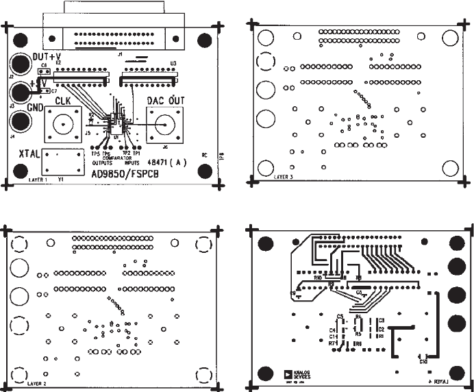
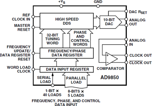
AD9850 Evaluation Board
Functional Block Diagram
Applications of AD9850
Sine Wave Synthesis and Flexibility
The AD9850 showcases its prowess in crafting precise sine waves with adaptable frequency and phase control. Its ability to smoothly adjust frequencies becomes a harmonious factor in varied testing and measurement settings, spanning research and commercial use. The elegance of swift phase modifications assists in enhancing signal coherence and diminishing phase noise, thereby reinforcing signal integrity in intricate systems.
Digital Clock Synchronization
With its precise timing capabilities, digital clock recovery finds a valuable partner in the AD9850. It seamlessly extracts timing details from data streams, ensuring synchronization. This proves mostly beneficial in telecommunications, where preserving data fidelity during transmission evokes trust. Actual applications demand agility to accommodate various data rates, and the AD9850's adaptability curtails errors from timing mismatches.
Enhancements in Communication Systems
Within communication systems, the AD9850 makes remarkable contributions by refining modulation and demodulation processes. Its stable frequency generation supports efficient data exchange. This device is often employed to boost signal clarity, fend off interference, and accommodate diverse communication protocols, ultimately transforming communication networks with enhanced signal quality and range.
Digital Precision in ADC Code Generation
Employing the AD9850 for digitally controlled ADC code generation highlights its precision in translating analog signals to digital codes. It plays a serious role in data acquisition systems demanding accurate digital signal representation. The reliability and accuracy of the AD9850 facilitate high resolution and faithful conversion of rapidly fluctuating signals, solidifying its role in high-precision arenas.
Agile Local Oscillator Uses
As an agile local oscillator, the AD9850 supports endeavors that require rapid frequency changes and stability, such as radars and testing instruments. Utilizing the AD9850 can elevate system performance, enabling swift adaptations to evolving conditions and preserving system precision over time, thus paving the way for technical innovations that stand the course.
Manufacturer
Analog Devices, Inc. (ADI), renowned for its inventive prowess in analog and mixed-signal advancements since 1965, has consistently positioned itself as a leader in electronic signal conversion. Its components play a major role in connecting the physical and digital worlds, reaching over 100,000 customers worldwide. These products transform sound, light, motion, and temperature into electrical signals, enriching the capabilities of myriad electronic devices. ADI's advanced technology permeates diverse sectors in telecommunications, healthcare, automotive, and consumer electronics.
Datasheet PDF
AD9850BRS Datasheets:
AD9850BRSZ Datasheets:
Frequently Asked Questions [FAQ]
1. Can the AD9850/1 be employed for radio transmission?
The AD9850 proves to be a compelling choice for constructing a low-power transmitter. It facilitates short to moderate-range transmissions using Frequency Shift Keying (FSK) modulation. In actual scenarios, you can harness its precision in amateur radio projects, carefully optimizing signal clarity and reliability within chosen frequency bands.
2. Which waveforms is the AD9850 capable of generating?
The AD9850 is adept at producing various waveforms like sine, square, and triangle. Utilizing its direct digital synthesis (DDS) abilities, you can intricately adjust these waveforms to meet different electronic experimental needs, highlighting this technology's adaptability in waveform creation.
3. How does the AD9850BRS differ from the AD9850?
The AD9850BRS model distinguishes itself with unique features concerning temperature range and packaging. These differences cater to applications where environmental factors require specific durability, ensuring sustained performance and longevity in diverse operational contexts.
4. For waveform generation, should one choose the MAX038 or the AD9850?
Choosing between the MAX038 and the AD9850 hinges on the specific needs of the application. Insights from highlight digital synthesis (AD9850) or an analog method (MAX038) are based on factors like precision, scalability, and ease of integration. Many find that digital pathways often provide enhanced adaptability for contemporary applications.
5. What is the AD9850 package in PROTEL?
In PROTEL, the AD9850 is offered in a DIP28 package. This format is appreciated for its accessibility in prototyping and educational settings, enabling streamlined assembly and testing in a variety of hardware and software development environments.
About us
ALLELCO LIMITED
Read more
Quick inquiry
Please send an inquiry, we will respond immediately.
LSM6DS3 IMU Sensor: Comprehensive Pinout, Features, and Datasheet Analysis
on October 28th
LTC6957HMS-3#TRPBF Clock Buffer: Specifications and Datasheet
on October 28th
Popular Posts
-

Complex Instruction Set Computers: How They Changed Computing?
on April 18th 147749
-

USB-C Pinout and Features
on April 18th 111916
-

Using Xilinx Unified Simulation Primitives: A Comprehensive Guide to FPGA Design and Simulation
on April 18th 111349
-

Power Supply Voltages in Electronics: Meaning of VCC, VDD, VEE, VSS, and GND
on April 18th 83714
-

RJ45 Connector Guide: Pinout, Wiring, Cable Types, and Uses
on January 1th 79502
-

The Ultimate Guide to Wire Color Codes in Modern Electrical Systems
The way our electrical systems use colors isn’t just for looks. Each wire color now indicates a specific function, making it easier to identify and handle electrical components correctly during ins...on January 1th 66872
-

Quality (Q) Factor: Equations and Applications
The quality factor, or 'Q', is important when checking how well inductors and resonators work in electronic systems that use radio frequencies (RF). 'Q' measures how well a circuit minimizes energy...on January 1th 63005
-

Purge Valve Guide: Function, Symptoms, Testing, and Replacement for Optimal Engine Performance
The purge valve is a key part of a car’s system that helps keep the air clean by managing fuel vapors before they can escape into the atmosphere. This not only helps the environment by reducing pol...on January 1th 62949
-

Achieving Peak Performance with the Maximum Power Transfer Theorem
The Maximum Power Transfer Theorem explains how energy from a source, such as a battery or generator, flows to a connected load. It shows the exact condition where the load receives the most power....on January 1th 54077
-

A23 Battery Specifications and Compatibility
The A23 battery is a small, cylinder-shaped battery with high voltage. Also called 23A, 23AE, or MN21, it runs at 12 volts and much higher than AA or AAA batteries. Its special design make...on January 1th 52091
HOT Part Number
-

BD9B100MUV-E2
Rohm Semiconductor
IC REG BUCK ADJ 1A 16VQFN
UPD70F3539AF5A9-PN7-Q-A
Renesas Electronics America Inc
IC MICROCONTROLLER
18081A621JAT2A
KYOCERA AVX
CAP CER 620PF 100V NP0 1808
FDN340P
onsemi
MOSFET P-CH 20V 2A SUPERSOT3
70231-101
Amphenol ICC (FCI)
CONN RCPT BLADE PWR 8POS EDGE MT
MPSW42RLRAG
onsemi
TRANS NPN 300V 0.5A TO92
MC7824BT
onsemi
IC REG LINEAR 24V 1A TO220AB
AD8009ARZ-REEL
Analog Devices Inc.
IC OPAMP CFA 1 CIRCUIT 8SOIC
LT1815CS5#TRPBF
Analog Devices Inc.
IC OPAMP VFB 1 CIRCUIT TSOT23-5
DG411DYZ
Renesas Electronics America Inc
IC SWITCH SPST-NCX4 35OHM 16SOIC
VFT2060C-M3/4W
Vishay General Semiconductor - Diodes Division
DIODE SCHOTTKY 20A 60V ITO-220AB
TSX562AIYST
STMicroelectronics
IC CMOS 2 CIRCUIT 8MINISO
MR256D08BMA45
Everspin Technologies Inc.
IC RAM 256KBIT PARALLEL 48FBGA
VSC3312YYP-01
Microchip Technology
IC SWITCH 16X16 6.5GBPS 196FCBGA
XC68HC908GP20CFB
Motorola
TSG 8BIT20K FLASH
CSR8811A08-ICXR-R
Qualcomm
IC RF TXRX+MCU BLUETOOTH
MPSW05
onsemi
TRANS NPN 60V 0.5A TO92
1N4055R
Solid State Inc.
DIODE GEN PURP REV 900V 275A DO9 -

ASX342ATSC00XPED0-DP
onsemi
IMAGE SENSOR VGA 1/4 CIS SOC
0433.125NR
Littelfuse Inc.
FUSE BOARD MNT 125MA 125VAC/VDC
1SMA5941BT3G
onsemi
DIODE ZENER 47V 1.5W SMA
DCP010512BP-U/700
Texas Instruments
DC DC CONVERTER 12V 1W
1-1734344-1
TE Connectivity AMP Connectors
CONN D-SUB HD RCPT 15P R/A SLDR
KSD1621STF
onsemi
TRANS NPN 25V 2A SOT89-3
BQ24161RGET
Texas Instruments
IC BATT CHG LI-ION 1CELL 24VQFN
BTA26-600BW
STMicroelectronics
TRIAC ALTERNISTOR 600V 25A TOP3
NCP1239DD65R2G
onsemi
IC OFFLINE SWITCH FLYBACK 7SOIC
TMS320TCI6482BZTZA
Texas Instruments
TMS320 - DIGITAL SIGNAL PROCESSO
BQ20Z90DBTR-V150
Texas Instruments
IC GAS GAUGE LI-ION 30TSSOP
PCMB104T-1R0MT
Susumu
FIXED IND 1UH 18A 3.3 MOHM SMD
CY29942AXCT
Infineon Technologies
IC CLK BUFFER 1:18 200MHZ 32TQFP
CC0402KRX7R9BB561
YAGEO
CAP CER 560PF 50V X7R 0402
STPS20M60SG-TR
STMicroelectronics
DIODE SCHOTTKY 60V 20A D2PAK
AT25010N-10SC-2.7
Microchip Technology
IC EEPROM 1KBIT SPI 3MHZ 8SOIC
04023A1R0CAT4A
KYOCERA AVX
CAP CER 1PF 25V C0G/NP0 0402
ISL6327IRZ
Intersil
SWITCHING CONTROLLER, VOLTAGE-MO -

LQW18AN75NG0ZD
Murata Electronics
FIXED IND
DFA100BA160
SanRex Corporation
DIODE MODULE 1600V 100A
BAR46AFILM
STMicroelectronics
DIODE ARRAY SCHOTTKY 100V SOT23
MAX825SEUK
Analog Devices Inc./Maxim Integrated
IC SUPERVISOR MPU
MMST2222A-7-F
Diodes Incorporated
TRANS NPN 40V 0.6A SOT323
FODM8801AR2
onsemi
OPTOISO 3.75KV TRANS 4-MINI-FLAT
FJV1845FMTF
Fairchild Semiconductor
SMALL SIGNAL BIPOLAR TRANSISTOR,
EVK105RH5R1JW-F
Taiyo Yuden
CAP CER 5.1PF 16V R2H 0402
6651170-3
TE Connectivity AMP Connectors
CONN EDGE DUAL FMALE 4POS 0.508
KSZ8893FQLI-FX
Microchip Technology
IC SWITCH ETH 3PORT 128QFP
170M6340
Eaton - Bussmann Electrical Division
FUSE SQUARE 400A 1.3KVAC RECT
BCM20741A2KFB1G
Broadcom Limited
SINGLE-CHIP BLUETOOTH
MAX3443EASA+
Analog Devices Inc./Maxim Integrated
IC TRANSCEIVER HALF 1/1 8SOIC
GRM0335C1H9R3DA01D
Murata Electronics
CAP CER 9.3PF 50V C0G/NP0 0201
TNY175PN
Power Integrations
11.5 W (85-265 VAC) 15 W (230 VA
742700726
Würth Elektronik
FERRITE CORE 278 OHM SOLID 4MM
DM74S20N
onsemi
IC GATE NAND 2CH 4-INP 14DIP
P4SMA56CA-E3/61
Vishay General Semiconductor - Diodes Division
TVS DIODE 47.8VWM 77VC DO214AC