Armatures in Electric Machines: Composition, Functionality, and Advanced Applications
Electric machines are important tools in everyday life and in big industries. At the heart of these machines is the armature, a key part that helps turn electrical energy into motion or motion into electrical energy. This guide dives deep into how armatures work in different machines like motors and generators. It explains how the parts of an armature work together to make machines run smoothly and efficiently. By breaking down the details of how armatures function, this article sheds light on how to get the best performance and save energy in electric machines.Catalog
Understanding Armatures
An armature is an excellent component of electric machines, enabling power generation through its interaction with magnetic fields. Depending on the machine's design, the armature can either rotate or stay stationary. It operates within a zone called the air gap, where it interacts with magnetic flux to produce electromotive force (EMF), ultimately creating mechanical motion. This magnetic field is generated by either permanent magnets or electromagnets, coils of wire that become magnetic when electricity flows through them. In certain machines, like doubly-fed systems, the magnetic field element can also act as an auxiliary armature, boosting control and energy conversion efficiency. For optimal performance, armatures are carefully designed to stay perpendicular to both the magnetic field and the direction of motion, force, or torque. This alignment maximizes the electromagnetic forces that drive the machine. Typically made from copper due to its electrical conductivity, the armature windings are arranged to efficiently generate EMF and convert energy. This design directly influences the machine's torque output, speed regulation, and overall efficiency.
An armature plays several roles in electric machines, directly influencing their efficiency and functionality. Its main job is to carry electric current within a magnetic field to produce torque in rotating machines or force in linear ones. This is based on electromagnetic induction, where movement between the armature and the magnetic field induces EMF. This EMF drives current through the armature windings, creating a magnetic force that converts electrical energy into mechanical motion or vice versa. In electric motors, the armature converts electrical energy into mechanical power. During this process, the induced EMF acts against the armature current, known as back EMF, which helps regulate speed and torque. Conversely, in generators, the armature converts mechanical energy into electrical energy, demonstrating its dual role in machines like motors and generators.
Electromotive Force (EMF) and Power Conversion Efficiency
The production of EMF within the armature is good for power conversion. According to Faraday's law of electromagnetic induction, EMF is generated by the relative motion between the armature and the magnetic field. Following Lenz's law, this EMF opposes the motion that creates it. In motors, this opposing EMF, or back EMF, regulates speed and torque by counteracting the input current, ensuring stable and efficient operation. When used in generators, the armature converts mechanical energy into electrical power. This conversion is enhanced by strategically designed windings and a well-planned magnetic circuit, which minimize energy losses and optimize energy transfer. The EMF’s polarity and intensity depend on the magnetic field's strength and the armature's rotation direction, allowing precise control over power output. This adaptability is need for variable-speed and load requirements in industrial and renewable energy systems.
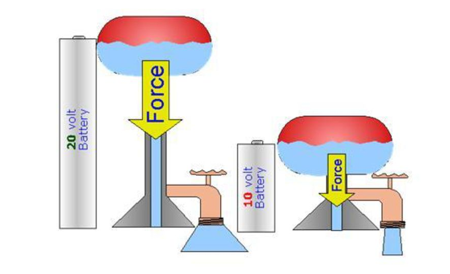
Figure 2. EMF Equation and Internal Resistance in a Circuit
Composition of Armature Components
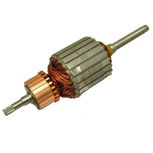
An armature is a main part of electric machines, responsible for converting electrical energy into mechanical energy and vice versa. It consists of several main components: the armature core, windings, commutator, and shaft. Each of these parts is carefully designed to improve the machine's efficiency, reduce power losses, and ensure durability. This section provides a detailed breakdown of each component, explaining how they contribute to the performance of electric motors and generators.
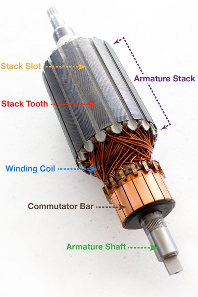
Figure 3. Labeled Armature Structure and Parts
Armature Core
The armature core is the magnetic backbone of the armature. Its main function is to support the windings and enhance the magnetic interactions needed for energy conversion. It is made from thin layers of silicon steel, called laminations, which are stacked together. This layered structure reduces eddy currents, unwanted circulating currents that cause energy loss and overheating. By limiting these currents to each thin layer, the laminated design greatly improves the machine's energy efficiency. Another important feature of the core is its ability to minimize hysteresis losses. These losses occur when the core material is repeatedly magnetized and demagnetized by the alternating magnetic field.
To reduce this, the core is made from high-quality silicon steel, which has low hysteresis loss properties. The laminations are carefully aligned, and the slots that hold the windings are precisely cut to maximize magnetic flow and minimize leakage. In some advanced designs, the slots are skewed to reduce magnetic cogging, a jerky motion that can occur when the rotor aligns with the stator's magnetic poles. This skewed slot design ensures smoother rotation and reduces vibrations, leading to quieter and more reliable machine operation.
Armature Windings
Armature windings are responsible for generating electromotive force (EMF) by conducting current through the machine's magnetic field. These windings are made from copper wire due to its excellent electrical conductivity. The wires are carefully insulated to prevent short circuits and maintain the integrity of the winding. The arrangement of the windings within the core slots is important for maximizing efficiency. There are two main types of winding configurations: lap winding and wave winding. Lap winding is used in applications that require high current at low voltage. It connects in parallel, providing multiple paths for the current, which increases the current capacity.
Wave winding is better suited for high-voltage, low-current applications. It connects in series, increasing the voltage while keeping the current lower. The choice of winding configuration directly impacts the machine’s torque, speed, and voltage characteristics, allowing customization for different operational needs. The placement and connection of the windings are strategically designed to optimize the magnetic field and reduce potential issues like arcing and vibration. Techniques such as skewing the windings or using multiple coils in a single slot enhance performance and minimize electromagnetic interference.
Armature Commutator
The commutator is an important component in DC machines. Its main role is to direct the current flow through the armature windings, ensuring consistent mechanical rotation or electrical output. It is made up of multiple copper segments, which are individually insulated from each other. These segments are connected to the armature windings and rotate with the shaft. As the armature rotates, the commutator switches the direction of current at precise moments. This switching keeps the torque in the motor constant or the output voltage in the generator stable. Proper timing is needed for maintaining smooth operation and avoiding interruptions in power flow.
To achieve this, the commutator is paired with carbon brushes that maintain sliding electrical contact with the rotating segments. The design and maintenance of the commutator are good for minimizing sparking and wear. High-quality insulation and precise machining of the copper segments ensure durability and reduce the risk of electrical faults. Regular maintenance is require to keep the commutator clean and free of dust or debris, which could interfere with the electrical contact. Proper brush tension and alignment also contribute to longer commutator life and more reliable machine performance.
Armature Shaft
The armature shaft is the central support structure for all rotating parts of the armature, including the core and commutator. It transmits the mechanical power generated by the motor or received by the generator. The shaft is designed to withstand rotational forces, torque, and vibrations during operation. Material selection is need for the shaft, as it needs to be strong, rigid, and durable. High-strength steel alloys are commonly used to provide the mechanical support while maintaining a relatively light weight to reduce inertia. The shaft also ensures precise alignment of the rotating components, for smooth operation and efficient power transfer.
Any misalignment could lead to mechanical losses, increased wear, and potential damage to the machine. To minimize friction and wear, the shaft is supported by high-precision bearings that allow smooth rotation. These bearings are carefully selected to handle the radial and axial loads experienced during operation. Proper lubrication and regular maintenance of these bearings are good for preventing overheating and extending the lifespan of the shaft and the entire armature assembly.
How an Armature Works?
An armature helps change electrical energy into movement in motors or change movement into electrical power in generators. This happens because of electromagnetic induction. This means that when you move a wire through a magnetic field, it creates an electric force (called EMF). The armature makes its own magnetic field, and this field interacts with the magnetic field from another part of the machine (called the field winding). This interaction is what makes the armature work.
How the Armature Works in Motors?

Figure 4. DC Motor Structure and Armature Operation
In electric motors, the armature changes electrical energy into movement. It does this by letting electric current flow through coils (called windings) placed in a magnetic field made by the stator. This magnetic field can come from either permanent magnets or electromagnets. When current goes through the armature windings, it reacts with the stator’s magnetic field and creates a force that makes the armature spin. To keep the armature spinning smoothly, a commutator and brushes are used. These parts work together to change the direction of the current at the right times. The brushes pass electricity to the commutator, which flips the direction of the current to keep the motor turning in the same direction. This switching stops the motor from getting stuck or spinning the wrong way. Fleming’s left-hand rule helps explain how this works. It shows that the direction of the magnetic field, the direction of the current, and the resulting force all work together to create rotation.
Several things affect how well the motor works. The armature windings are arranged to maximize magnetic interaction while reducing resistance, making energy conversion more efficient. The commutator is designed to switch the current smoothly with minimal sparking or wear. Using materials like copper helps lower electrical resistance and improves power transfer. Modern motors also have control systems that manage current, speed, and torque. These systems allow precise adjustments, making the motor useful for a wide range of applications, from home appliances to industrial machines.
How the Armature Works in Generators?

Figure 5. DC Generator Operation with EMF Generation and Rectification
In generators, the armature does the opposite of what it does in motors: it changes movement into electrical energy. This also uses electromagnetic induction. When the armature spins inside a magnetic field made by the stator, it cuts through the magnetic lines, creating EMF (electromotive force) in its windings. This spinning is powered by something like a turbine or engine. Because the armature moves through changing north and south magnetic poles, it makes an alternating current (AC). In DC generators, a commutator changes this AC into direct current (DC) by switching the output at the right times. In AC generators (also called alternators), the output stays as AC, and its frequency depends on how fast the armature spins.
Several things affect how well the generator works. Faster rotational speed changes the magnetic field more quickly, producing more EMF. A stronger magnetic field also creates more EMF, increasing power output. The windings are arranged to maximize magnetic interaction while minimizing energy loss. Modern generators use voltage regulators to maintain steady voltage and frequency, which is important for devices that need consistent power. These systems adjust the magnetic field to balance changes in power use or input speed.
Generators are important for producing power and keeping it steady. By improving the armature design and adding control systems, You can make generators more efficient and reliable. This helps keep steady voltage and frequency for power grids, provide reliable power in renewable energy systems where the power source changes, and ensure backup power for places like hospitals and data centers. Improving how the armature works in both motors and generators makes electric machines more efficient, reliable, and flexible, meeting today’s power needs.
Techniques in Armature Control
Controlling the armature in electric motors help optimize performance, particularly in regulating speed and managing torque. In DC motors, the built-in resistance of the armature naturally limits current, protecting the motor from electrical and thermal overloads. However, to achieve more precise control over speed and to adapt to different operational needs, external resistance is often added to the circuit. This adjustable resistance allows operators to fine-tune the armature current, directly influencing the motor’s speed and torque characteristics.
The speed of a DC motor is primarily determined by the balance between the back electromotive force (EMF) and the armature current. Back EMF is generated as the motor rotates within a magnetic field, opposing the direction of the armature current. This relationship can be expressed as:
![]()
Where:
• 𝑁 = Motor speed
• 𝐸𝑏 = Back EMF
• 𝐼𝑎 = Armature current
• 𝑅𝑎 = Internal armature resistance
To gain better control over motor speed, an external resistance (𝑅𝑐) is introduced into the armature circuit, modifying the equation to:
![]()
This shows that motor speed is inversely proportional to the total resistance in the armature circuit. By adjusting 𝑅𝑐, the total resistance can be fine-tuned, allowing precise speed control.
• Increasing 𝑅𝑐: This reduces the armature current, leading to a smaller voltage drop across the resistance. As a result, the back EMF increases, causing the motor speed to rise.
• Decreasing 𝑅𝑐: This increases the armature current, resulting in a greater voltage drop, which lowers the back EMF and decreases the motor speed.
This method is widely used in both shunt and series DC motors because of its simplicity and cost-effectiveness.
Armature Winding and Reaction
Armature winding creates voltage and produces electromotive force (EMF). It works with the magnetic field made by the field winding. This teamwork helps change electrical energy into mechanical energy in motors and mechanical energy into electrical energy in generators. To make electric machines work better and last longer, it’s important to understand how armature winding is designed and how it works. It’s also important to know about armature reaction, which can cause some challenges.
Armature Winding
Armature winding is made up of several coils of conductive wire, usually copper because it conducts electricity well. These coils are placed carefully inside the slots of the armature core. This setup maximizes the magnetic interaction and reduces flux leakage, which helps the electric machine work more efficiently. The way these coils are arranged determines the winding type, which greatly influences the machine's performance.
There are two main types of winding configurations: Lap Winding and Wave Winding. Lap Winding creates multiple parallel paths for the current to flow, making it suitable for high-current, low-voltage uses, such as heavy-duty motors. In contrast, Wave Winding connects the coils in series, which increases the voltage while keeping the current lower. This type is ideal for high-voltage, low-current applications like transmitting power over long distances. To keep the electrical system safe and reliable, the coils are well insulated to avoid short circuits. They are also connected to the commutator, which changes the direction of the current at the right times, ensuring consistent torque in motors or steady voltage output in generators.
There are also advanced winding techniques, such as Distributed Winding and Concentrated Winding. Distributed Winding spreads the coils across multiple slots, which helps balance the magnetic flux and reduces electrical noise. On the other hand, Concentrated Winding groups the coils into fewer slots, increasing power density and making the machine more compact. Choosing the right winding configuration and technique affects the machine's efficiency, torque, and stability during operation.
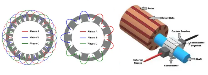
Figure 6. Armature Winding Types and Magnetic Interaction
Armature Reaction
Armature reaction happens when the magnetic field created by the armature current interacts with the main magnetic field produced by the field winding. This interaction can either strengthen or weaken the main field, leading to issues like distortion of the magnetic field or a decrease in magnetic flux. These changes can affect the performance and efficiency of the electric machine.
In DC machines, armature reaction can distort the main magnetic field, leading to several problems. Field Distortion changes the shape of the magnetic field, which reduces efficiency and causes uneven torque. Neutral Plane Shift happens when the area with no induced EMF moves, making it harder to switch current direction smoothly. This misalignment can cause sparking at the brushes, which may damage the commutator. Additionally, Flux Weakening can occur if the armature’s magnetic field opposes the main field, leading to a reduction in total flux and weakening the motor’s torque output.
Armature reaction occurs in several steps. First, the field winding creates a steady magnetic field. As the armature rotates, it moves through this field, generating an EMF that causes current to flow through the armature windings. This current produces its own magnetic field, which interacts with the main field. This interaction distorts the main magnetic flux, causing the neutral plane to shift and affecting the commutation process. If this distortion isn’t controlled, it can lead to more sparking at the brushes, lower efficiency, and uneven torque production.
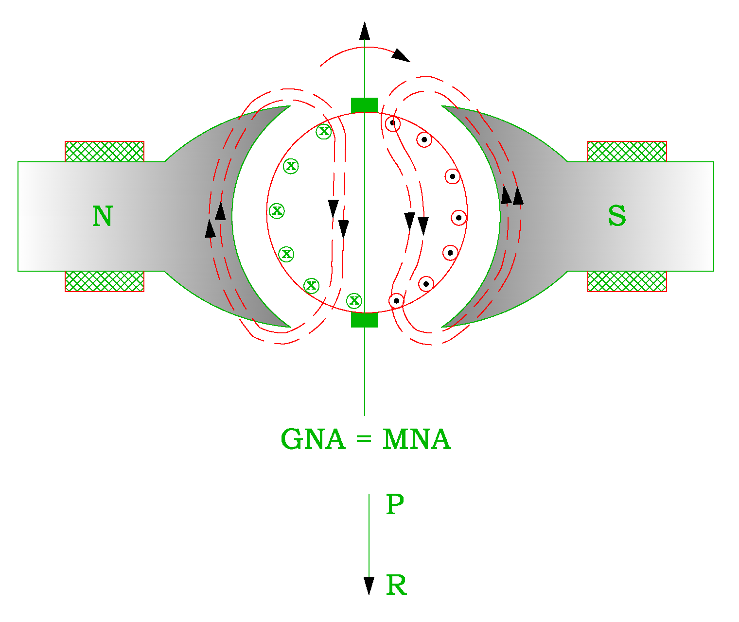
Figure 7. Armature Reaction in DC Machine
Examination of Armature Losses
Armature losses are a great factor influencing the efficiency and performance of electric machines, including both motors and generators. These losses occur during the energy conversion process and can reduce overall system efficiency. The three primary types of armature losses are copper loss, eddy current loss, and hysteresis loss, each resulting from distinct physical mechanisms. Understanding the nature of these losses and implementing strategies to minimize them is require for optimizing the performance and efficiency of electric machines.
Copper Losses
Copper loss, also called I²R loss, happens because of the electrical resistance in the armature winding when current passes through it. This resistance produces heat, which leads to power loss and lowers the machine's efficiency. The amount of copper loss increases rapidly with higher current levels, under heavy load conditions. To reduce copper losses, you can use thicker conductors with larger cross-sectional areas, which have less resistance and allow more current to flow with less power loss. Another approach is to use high-conductivity materials like copper, or even silver for special cases, as they conduct electricity more efficiently.
Designing the winding layout more efficiently can minimize the length of conductors, which reduces resistance. Advanced cooling systems, such as forced air or liquid cooling, also play a role by dispersing the heat produced, keeping the armature at safe temperatures and protecting the winding insulation from damage. By carefully choosing materials, optimizing the winding design, and using effective cooling techniques, copper losses can be reduced. This not only boosts the efficiency of the machine but also enhances its overall performance and lifespan.
Eddy Current Losses
Eddy current losses happen when changing magnetic fields create circulating currents inside the armature core. These circulating currents produce opposing magnetic fields, which waste energy as heat and reduce the efficiency of the machine. The amount of eddy current loss depends on several factors, including the strength of the magnetic field (magnetic flux density), the speed at which the magnetic field changes (frequency of flux reversal), and the thickness of the core’s layers (laminations). If these currents are not controlled, they can cause energy loss and overheating, affecting the overall performance and durability of the machine.
To minimize eddy current losses, many design the armature core using thin, insulated layers (laminations) of magnetic steel. These laminations increase electrical resistance between layers, making it harder for eddy currents to flow and reducing energy loss. Choosing the right thickness for these layers is important because thinner laminations limit eddy currents more effectively, though they can be costlier and hard. Coating each lamination with a high-resistance material also helps block eddy currents. Using magnetic materials with high electrical resistivity and low hysteresis loss, like silicon steel, reduces eddy currents while maintaining good magnetic performance. By optimizing the core design and selecting the best materials, eddy current losses can be lowered, leading to better efficiency and performance.
Hysteresis Losses
Hysteresis losses happen because the armature core is repeatedly magnetized and demagnetized as the magnetic field changes direction. Every time the magnetic field switches, the core material resists the change, using up energy that is released as heat. This constant cycle of magnetization and demagnetization leads to energy loss, which reduces the overall efficiency of the machine. The amount of hysteresis loss depends on the magnetic properties of the core material and how often the magnetic field changes direction. If the material resists changes in magnetization strongly, more energy is wasted as heat. Similarly, faster changes in the magnetic field (higher frequency) increase hysteresis losses.
To minimize hysteresis losses, others use materials with low coercivity, like silicon steel, which require less energy to change their magnetic alignment. These materials easily switch magnetic states with minimal energy loss. High-permeability materials are also effective because they allow magnetic flux to pass through more easily, reducing the energy needed for magnetization cycles. For AC machines, grain-oriented silicon steel is useful because its magnetic domains align more efficiently, lowering energy loss during rapid field changes. Designing the core with a uniform magnetic field distribution helps prevent localized losses. By choosing the right materials and optimizing the core’s design, hysteresis losses can be reduced, leading to better efficiency and performance in electric machines.
Armature Design Considerations
The design of an armature is very important for how well electric machines like motors and generators work. A good armature design helps the machine change energy efficiently, produce high power, and reduce energy losses. This means the machine will work better, use less electricity, and last longer. To make the armature as efficient as possible, several design factors need to be considered. These include the size and shape of the armature, the type of materials used, and the way the windings are arranged. By carefully choosing and optimizing each of these details, the armature can be made to meet specific performance needs, ensuring the machine runs smoothly and efficiently.
Number of Slots
The number of slots in an armature core plays a role in how magnetic flux moves, how efficiently current flows, and how stable the winding is. Slots hold the coils in place and provide support, ensuring the winding stays secure and properly insulated. Choosing the right number of slots is great for the machine to work well. The ideal slot count depends on a few factors. First, the winding type matters because different winding designs need specific slot arrangements to perform their best. Second, the number of poles in the machine must match the slot count to keep the magnetic flux balanced. Finally, power and size requirements are valuable to larger machines usually need more slots to manage higher power and voltage. By considering these factors, you can find the best slot count that improves performance, maintains stability, and meets power demands. This careful balance helps the machine run efficiently and reliably.

Figure 8. Cross-sectional View of Armature Core Slots and Winding Placement
Advantages of More Slots
Improved Magnetic Flux Distribution: When there are more slots in the armature core, the magnetic flux can be distributed more evenly and precisely, which reduces reactance and minimizes harmonic interference that could otherwise cause unwanted vibrations or noise; as a result, this leads to smoother torque output and more stable operation of the machine, enhancing its overall performance and reliability.
Enhanced Current Flow Efficiency: By spreading the current across a greater number of slots, the electrical resistance and eddy current losses are reduced, which means less energy is wasted as heat, ultimately increasing the overall efficiency of the machine and allowing it to operate more effectively under varying load conditions.
Disadvantages of More Slots
Increased Complexity and Cost: Although adding more slots can improve performance, it also makes the manufacturing process much more complicated because it requires more precise machining and assembly, which in turn raises production costs due to the need for advanced equipment, additional materials, and longer production times.
Weight and Space Constraints: Incorporating a higher number of slots inevitably increases the overall weight of the armature core and reduces the available space for insulation and cooling systems, which can create challenges in thermal management and may require more advanced cooling solutions to prevent overheating and ensure safe operation.
Leakage Flux and Armature Reaction: While more slots can enhance magnetic flux distribution, they can also lead to an increase in leakage flux and amplify armature reaction effects, which may disrupt the magnetic field and reduce efficiency, impacting the stability and performance of the machine, especially under heavy load conditions.
Slot Shape
The shape of the armature slots plays a role in how magnetic flux moves, how much leakage flux occurs, and how efficiently the machine operates. The slots are where the coils are placed, and their shape affects the magnetic field and cooling of the machine. There are two main types of slot shapes: open slots and closed slots, each with its own advantages and disadvantages.
Open Slots are easier to manufacture because they have a simpler design that requires less precise machining. They also allow better cooling since the open shape improves airflow around the coils, helping to remove heat more effectively. This makes open slots a good choice for machines that operate at high currents and need efficient cooling to prevent overheating. However, open slots increase magnetic reluctance, which makes it harder for the magnetic flux to pass through the core. This leads to higher leakage flux, which can reduce the overall efficiency of the machine because some of the magnetic energy is wasted.
Closed Slots, on the other hand, are designed to contain the magnetic field more effectively, which reduces magnetic reluctance and minimizes leakage flux. This results in better efficiency and higher power output because more of the magnetic energy is used effectively. However, closed slots are more difficult to manufacture due to their complex shape, which requires precise machining and higher production costs. Closed slots provide less cooling since airflow is more restricted, which can be a drawback in high-current applications like heat dissipation. Despite these challenges, closed slots are often chosen for high-performance applications where efficiency and power output are more important than cooling or manufacturing cost.
Choosing between open and closed slots depends on several factors. Efficiency requirements are a major consideration, closed slots are selected for applications that need high efficiency, such as electric vehicles and precision industrial machinery, because they reduce leakage flux and improve power output. Open slots are easier and cheaper to produce, making them a good choice for cost-sensitive designs. Cooling needs are another factor, open slots are preferred when better cooling is needed, such as in high-current machines that generate a lot of heat. You must carefully select the slot shape by analyzing the operational requirements and performance goals of the machine. They must balance the need for high efficiency, effective cooling, and manageable manufacturing complexity. This often involves using computer simulations to predict how different slot shapes will impact performance and efficiency under various operating conditions.
Winding Type
Choosing the right winding type for an armature is needed because it directly affects the machine’s voltage, current handling, power output, and efficiency. The winding configuration determines how electrical energy is converted into mechanical power and vice versa. There are two main types of windings used in electric machines: Lap Winding and Wave Winding, each designed for specific applications and performance requirements.
Lap Winding is designed to provide multiple parallel paths for current flow, making it suitable for high-current, low-voltage applications. This type of winding is commonly used in heavy-duty motors, such as those in industrial equipment and traction systems, where high torque at low speeds is needed. Because the coils are connected in parallel, lap winding can handle large currents without overheating, which improves the machine’s durability and performance under heavy loads. However, this configuration produces lower voltage, making it less suitable for long-distance power transmission or high-voltage applications.
Wave Winding, on the other hand, connects the coils in series, which increases the voltage while reducing the current flowing through each coil. This makes wave winding ideal for high-voltage, low-current applications, such as generators and power transmission systems that need to send electricity over long distances. Wave winding also provides better commutation, meaning smoother current switching at the brushes because the series connection ensures a more even distribution of current. This reduces the risk of sparking at the brushes and increases the machine’s efficiency and lifespan. However, wave winding is more complex to design and manufacture compared to lap winding, which can increase production costs.
When choosing a winding type, you’ll want to think about a few key things. If you need high torque at low speeds, lap winding is a good choice because it handles high currents well. On the other hand, if you’re looking for high speed and high voltage, wave winding is better since its series setup works well for that. It also gives you smoother commutation, which means less sparking and less wear on the brushes. Wave winding helps reduce harmonic distortion and boosts efficiency, especially in high-voltage situations. To figure out the best option, you can use modeling and simulation tools to see how each winding type affects power output, efficiency, commutation, and harmonic distortion. By weighing all these factors, you can pick the winding setup that fits your needs best, making sure your machine runs smoothly, efficiently, and cost-effectively.
Conductor Size
The size of the conductor used in the armature winding is another factor because it directly impacts current density, copper losses, and heat generation. Larger conductors have lower electrical resistance, which means they reduce copper losses and generate less heat. This makes them ideal for high-current applications where efficiency and durability are important. However, using larger conductors also increases the overall weight of the armature and takes up more space, which can be a problem in compact designs or weight-sensitive applications.
On the other hand, smaller conductors are lighter and take up less space, making them suitable for compact designs, such as electric vehicles where weight is a great factor. However, smaller conductors have higher resistance, which leads to greater copper losses and can cause the winding to overheat if not properly cooled. This is why you need to carefully balance the conductor size based on the application’s requirements. For example, current-carrying capacity is a key consideration, larger conductors are needed for high-current applications, while smaller conductors work well in designs where weight and space are limited. Cooling requirements also play a role, as larger conductors generate less heat, reducing the demand on cooling systems.
Air Gap Dimensions
The air gap between the armature and the stator is another factor that affects magnetic flux density, power output, and operational efficiency. A smaller air gap increases the magnetic flux density, which improves magnetic coupling and overall efficiency because the magnetic field is stronger and more focused. This results in better power output and performance. However, smaller air gaps also increase armature reaction and leakage flux, which can cause instability and overheating, especially under heavy load conditions. You must be cautious when designing small air gaps to avoid these potential issues.
In contrast, a larger air gap reduces the magnetic flux density, which decreases power output but minimizes leakage flux and armature reaction. This makes the machine more stable and reliable, although it sacrifices some efficiency. Larger air gaps are often used in applications where stability and smooth operation are more important than maximum power output. By adjusting the air gap dimensions, you can control the balance between efficiency, power output, and operational stability.
Testing Procedures for Armature
Regular testing of an armature is good for maintaining the performance and extending the life of electric motors. Faults like open circuits, short circuits, or physical damage can lead to inefficiencies, overheating, or even complete motor failure. By performing thorough tests, potential issues can be identified early, allowing for timely repairs and preventing costly breakdowns. This section covers effective methods for assessing the structural and functional integrity of armatures, focusing on common faults that can impact efficiency.
Step 1: Prepare for Testing
Before beginning any tests, disconnect the armature from the motor. This prevents interference from other components that could affect the accuracy of your readings. It’s also important to ensure the armature is clean and dry, as dirt or moisture can lead to false measurements. Gather all necessary tools, including an ohmmeter for resistance checks and other diagnostic equipment as needed.
Check the work area for safety, making sure it’s clean and well-lit. Having a safe and organized workspace reduces the risk of accidents and makes the testing process more efficient. Make sure all testing equipment is in good working condition and calibrated correctly for accurate results. Proper preparation helps ensure reliable testing and accurate diagnosis.
Step 2: Check for Open and Shorted Windings
Use an ohmmeter to measure resistance across the armature windings. To do this, place one probe on a commutator bar and the other on the bar directly opposite, about 180 degrees apart. This checks the resistance of a complete coil winding. If the windings are in good condition, the resistance readings should be consistent across all coils.
If the resistance is too low, it indicates a short circuit, which could be due to damaged insulation or overlapping windings. If the resistance is too high or shows infinity, it suggests an open circuit, possibly from a broken wire or loose connection. In such cases, inspect the insulation for damage and check all connections. Repair or replace faulty sections as needed.
Step 3: Test Adjacent Commutator Bars
For a more detailed check, measure resistance between adjacent commutator bars. Start at one bar and move sequentially around the armature. This method tests each coil individually and helps pinpoint specific faults. Consistent resistance readings indicate the winding segments are functioning correctly. If the resistance is too low between two bars, it suggests shorted turns caused by insulation failure. High resistance could mean a partially open circuit due to damaged or corroded connections. In either case, inspect the affected area closely. Replace damaged insulation or rewind the faulty coil if necessary. If connections are loose or corroded, clean and resolder them.
Step 4: Assess Commutator Insulation
To check the insulation of the commutator bars, use an ohmmeter to measure resistance between each bar and the armature core. High resistance or no continuity indicates good insulation, while low resistance suggests a short circuit. This could be due to damaged insulation or conductive debris on the commutator surface. If a short circuit is detected, clean the commutator thoroughly to remove any debris. If cleaning doesn’t resolve the issue, inspect the insulation for damage. Re-insulate the affected bars or resurface the commutator if it is worn or uneven. Ensuring proper insulation is good for reliable motor operation.
Step 5: Document Findings and Perform Repairs
Record all resistance readings and note any irregularities. Keeping accurate records helps in diagnosing issues and planning targeted repairs. Mark faulty areas for easy identification during the repair process. Proper documentation also aids in tracking recurring problems over time. Once faults are identified, carry out the necessary repairs. This could involve replacing damaged insulation, rewinding coils, or resoldering loose connections. Ensure all repairs meet safety and quality standards. After repairs, retest the armature to confirm that all issues have been resolved.
Step 6: Implement Preventive Maintenance
Regular testing is need for preventive maintenance. Schedule periodic checks to detect early signs of wear, which can help avoid major breakdowns. This proactive approach extends the motor’s lifespan and maintains efficiency. It also reduces unexpected downtime and costly repairs. Using advanced diagnostic tools like digital ohmmeters and insulation resistance testers improves testing accuracy. Establishing a preventive maintenance routine helps keep motors operating efficiently for longer periods.
Armature Applications
Armatures are useful in many areas because they can be used in different ways. You can find them in power plants, cars, factories, and everyday electronics. This section looks at the many ways armatures are used, showing how they help modern technology work better and save energy. By learning about these uses, we can see why armatures are so important for both old and new.
Hydroelectric Power Plants
In hydroelectric power plants, armatures are integrated into turbines that convert the mechanical energy of flowing water into electrical energy. When water flows through the turbine, it spins a rotor connected to the armature. This rotation induces an electromagnetic field, generating electricity. These systems are commonly used in dams and hydroelectric stations worldwide, providing a reliable source of renewable energy. The use of armatures in hydroelectric power contributes to sustainable energy production by reducing dependence on fossil fuels and minimizing carbon emissions. They enable efficient energy conversion, ensuring that the potential energy of water is maximized for power generation.
Wind Turbines
In wind energy systems, armatures play a role by rotating with the turbine blades. As wind turns the blades, the connected rotor (containing the armature) spins within a magnetic field, generating electricity through electromagnetic induction. This process effectively converts kinetic energy from the wind into electrical power. Armatures in wind turbines are designed to operate at variable speeds, allowing them to adapt to changing wind conditions while maintaining efficient power generation. This capability is great for maximizing energy output and ensuring grid stability. By harnessing renewable wind energy, armatures in wind turbines contribute to reducing carbon emissions and promoting sustainable energy solutions.
Portable Generators
Portable generators rely on compact armatures to produce electricity for backup power or off-grid energy needs. These generators are important during power outages, emergencies, or outdoor activities, providing a reliable source of electricity in remote locations. Armatures in portable generators are designed for durability and efficiency, ensuring consistent performance under various conditions. They convert mechanical energy from internal combustion engines or other power sources into electrical energy, powering devices such as lights, appliances, and communication equipment. Their portability and efficiency make them great for disaster relief, camping, and other off-grid applications.
DC Motors
Armatures are important components in DC motors, which are widely used in industrial machinery, robotics, and electric vehicles. In these motors, the armature rotates within a magnetic field when electrical current passes through it, generating torque and causing movement. DC motors are known for their high starting torque and precise speed control, making them ideal for applications requiring variable speed and rapid acceleration. In robotics and automation, armature-driven DC motors enable precise movements and positioning, enhancing the accuracy and efficiency of complex tasks. In electric vehicles, they contribute to smooth acceleration and regenerative braking, improving energy efficiency and driving performance.
Electric Vehicles (EVs)
In electric and hybrid vehicles, armatures are good for the propulsion systems that drive the wheels. These armatures generate high torque at low speeds, which is great for urban driving conditions, such as quick starts and stop-and-go traffic. They enable regenerative braking, a feature that recovers kinetic energy during braking and converts it into electrical energy. This recovered energy is stored in the vehicle’s battery, extending its driving range and improving overall energy efficiency. The advanced design of armatures in EVs ensures high performance, reduced energy consumption, and lower environmental impact, supporting the global transition to sustainable transportation.
Robotics and Automation
In robotics and automation systems, armatures are used in servo motors and stepper motors to provide accurate positioning and speed control. These motors are used for automated manufacturing systems, robotic arms, and precision machinery, where high accuracy and repeatability are required. Armatures in these applications enable smooth and precise movements, allowing robotic systems to perform complex tasks with consistency and efficiency. Their reliability and precision enhance productivity in industries such as electronics manufacturing, automotive assembly, and medical device production. By driving innovation in automation, armatures contribute to increased operational efficiency and reduced human error.
Automotive Alternators
In automotive applications, stationary armatures are used in alternators to generate AC power as the engine drives a rotating magnetic field. Unlike traditional generators, this design eliminates moving electrical contacts, reducing wear and maintenance requirements. The generated AC power is then converted into DC to charge the vehicle’s battery and power electronic systems, including lights, infotainment, and engine control units. Armatures in automotive alternators are engineered for high efficiency and durability, ensuring consistent power supply under various driving conditions. This technology enhances vehicle reliability and supports the growing demand for advanced electronic features in modern vehicles.
Synchronous Generators
Synchronous generators, commonly used in power plants and grid applications, incorporate stationary armatures as part of their design. These generators convert mechanical energy from turbines powered by steam, water, or gas into electrical power through electromagnetic induction. The stationary armature design improves efficiency and reduces mechanical complexity, contributing to reliable and continuous power generation. Synchronous generators are use for large-scale power transmission, as they maintain a constant frequency and voltage, ensuring grid stability and meeting high power demands. Their role in power plants is best for supporting industrial, commercial, and residential energy needs worldwide.
Conclusion
Exploring armatures shows us the inner workings of the machines that power our world. From understanding the basic forces at play to examining the detailed design of armatures, each part contributes to making electric machines more efficient and effective. This guide not only covers the basics but also explains the latest improvements and considerations in design that lead to better and more eco-friendly machines.
About us
ALLELCO LIMITED
Read more
Quick inquiry
Please send an inquiry, we will respond immediately.
Frequently Asked Questions [FAQ]
1. What is the function of the armature current?
The armature current powers the armature, which is a key component in motors and generators. In motors, this current interacts with the magnetic field created by the stator (or permanent magnets in some designs), producing torque that turns the motor's shaft. In generators, the armature current is the output current generated as the armature spins within a magnetic field, converting mechanical energy into electrical energy.
2. What is the difference between armature and commutator?
The armature and the commutator are both parts of electric motors and generators, but they serve different functions. The armature is the rotating coil or coils within a magnetic field that either produce mechanical energy from electrical energy (in motors) or electrical energy from mechanical energy (in generators). The commutator, on the other hand, is a specific type of rotary electrical switch in direct current (DC) machines that periodically reverses the current direction between the rotor and the external circuit, ensuring that the torque or the electromagnetic force acts in one consistent direction.
3. What is the difference between stator and armature?
The stator and the armature are parts of an electric machine, but they differ in their roles and physical properties. The stator is the stationary part of the machine and contains coils that create a magnetic field or interact with the magnetic field of the armature. The armature is usually the rotating part that includes the coils where the input or output current flows, generating motion or electricity depending on whether the device is a motor or a generator.
4. What are the signs of a bad armature?
Signs of a bad armature can include sparking at the brushes, unusual noises, excessive heat generation, and a noticeable decrease in motor performance. On a technical level, a faulty armature may show a short or open circuit in its windings or uneven wear on the commutator. Testing with a multimeter or a growler can confirm these issues, indicating damage or malfunction that requires repair or replacement.
5. What is the purpose of the armature?
The purpose of the armature in electric machines is twofold: in electric motors, it converts electrical energy into mechanical energy to drive a mechanical load. In generators, it converts mechanical energy into electrical energy, providing power for external circuits. The armature's interaction with the magnetic field, facilitated by its windings and rotation (or movement in linear actuators), is central to the functioning of these machines.
ADG412BR: Features, Applications, Specifications, and Pinout
on February 27th
Everything You Need to Know About LFSCM3GA15EP1-7FN900C FPGA
on February 26th
Popular Posts
-

Complex Instruction Set Computers: How They Changed Computing?
on April 18th 147753
-

USB-C Pinout and Features
on April 18th 111925
-

Using Xilinx Unified Simulation Primitives: A Comprehensive Guide to FPGA Design and Simulation
on April 18th 111349
-

Power Supply Voltages in Electronics: Meaning of VCC, VDD, VEE, VSS, and GND
on April 18th 83714
-

RJ45 Connector Guide: Pinout, Wiring, Cable Types, and Uses
on January 1th 79502
-

The Ultimate Guide to Wire Color Codes in Modern Electrical Systems
The way our electrical systems use colors isn’t just for looks. Each wire color now indicates a specific function, making it easier to identify and handle electrical components correctly during ins...on January 1th 66872
-

Quality (Q) Factor: Equations and Applications
The quality factor, or 'Q', is important when checking how well inductors and resonators work in electronic systems that use radio frequencies (RF). 'Q' measures how well a circuit minimizes energy...on January 1th 63005
-

Purge Valve Guide: Function, Symptoms, Testing, and Replacement for Optimal Engine Performance
The purge valve is a key part of a car’s system that helps keep the air clean by managing fuel vapors before they can escape into the atmosphere. This not only helps the environment by reducing pol...on January 1th 62956
-

Achieving Peak Performance with the Maximum Power Transfer Theorem
The Maximum Power Transfer Theorem explains how energy from a source, such as a battery or generator, flows to a connected load. It shows the exact condition where the load receives the most power....on January 1th 54078
-

A23 Battery Specifications and Compatibility
The A23 battery is a small, cylinder-shaped battery with high voltage. Also called 23A, 23AE, or MN21, it runs at 12 volts and much higher than AA or AAA batteries. Its special design make...on January 1th 52092
HOT Part Number
-

RMPA0959
onsemi
IC RF AMP CELL 824-849MHZ 11LCC
RCLAMP0554S.TCT
Semtech Corporation
TVS DIODE 5VWM 15VC SOT23-6
CM453232-R47KL
Bourns Inc.
FIXED IND 470NH 545MA 320MOHM SM
744028002
Würth Elektronik
FIXED IND 2.2UH 1.3A 155MOHM SMD
MIC3809YMM
Microchip Technology
IC REG CTRLR MULT TOPOLOGY 8MSOP
AONS36302
Alpha & Omega Semiconductor Inc.
MOSFET N-CH 30V 146A 8DFN
SP3238EEA-L/TR
MaxLinear, Inc.
IC TRANSCEIVER FULL 5/3 28SSOP
BF5020WH6327
Infineon Technologies
N-CHANNEL POWER MOSFET
C1608X8R1H102M080AE
TDK Corporation
CAP CER 1000PF 50V X8R 0603
TPS71525QDCKRQ1
Texas Instruments
IC REG LINEAR 2.5V 50MA SC70-5
170M5444
Eaton - Bussmann Electrical Division
FUSE SQUARE 500A 1.3KVAC RECT
IHLP4040DZER220M1A
Vishay Dale
IHLP-4040DZ-1A 22 20% ER E3
C0603X181J1HACAUTO
KEMET
CAP CER 0603 180PF 100V ULTRA ST
PIC16F1575-E/JQ
Microchip Technology
IC MCU 8BIT 14KB FLASH 16UQFN
OPA4354AIPWR
Texas Instruments
IC CMOS 4 CIRCUIT 14TSSOP
P6SMB33A
Bourns Inc.
TVS DIODE 28.2VWM 45.7VC DO214AA
GCM1885C1H4R4CA16D
Murata Electronics
CAP CER 4.4PF 50V C0G/NP0 0603
R5F100LGAFB#10
Renesas Electronics America Inc
IC MCU 16BIT 128KB FLASH 64LFQFP -
TC621CCOA
Microchip Technology
THERMOSTAT PROG ACTIVE LOW 8SOIC
IRG4BC20UDPBF
International Rectifier
IGBT, 13A I(C), 600V V(BR)CES, N
MICROSMD175F-2
Littelfuse Inc.
PTC RESET FUSE 6V 1.75A 1210
AC0603KRX7R8BB222
YAGEO
CAP CER 2200PF 25V X7R 0603
1812AA150JAT1A\SB
KYOCERA AVX
CAP CER 15PF 1KV NP0 1812
SY10ELT22ZC
Microchip Technology
IC TRANSLTR UNIDIRECTIONAL 8SOIC
SCW03B-12
MEAN WELL USA Inc.
DC DC CONVERTER 12V 3W
A4840
Sensata-Crydom
SSR RELAY SPST-NO 40A 80-530V
TC4426AEOA
Microchip Technology
IC GATE DRVR LOW-SIDE 8SOIC
C1608NP01H470J080AA
TDK Corporation
CAP CER 47PF 50V NP0 0603
GRM1555C2A8R1DA01J
Murata Electronics
CAP CER 8.1PF 100V C0G/NP0 0402
INA330AIDGST
Texas Instruments
IC OPAMP GP 1 CIRCUIT 10VSSOP
12061C273KAT2A
KYOCERA AVX
CAP CER 0.027UF 100V X7R 1206
74LX1G70CTR
STMicroelectronics
IC BUF NON-INVERT 5.5V SOT323-5
CSNE151-204
Honeywell Sensing and Productivity Solutions
SENSOR CURRENT HALL 90A AC/DC
LF353DT
STMicroelectronics
IC OPAMP JFET 2 CIRCUIT 8SOIC
SMK316B7223KLHT
Taiyo Yuden
CAP CER 0.022UF 630V X7R 1206
R9G01612XX
Powerex Inc.
DIODE GP 1.6KV 1200A DO200AB -
FPF2300MPX
Fairchild Semiconductor
DUAL OUTPUT CURRENT LIMIT SWITCH
HZB6.8MWATL-E
Renesas Electronics America Inc
TVS DIODE 3.5VWM 3CMPAK
P0111MA 1AA3
STMicroelectronics
SCR 600V 800MA TO92-3
88E1545-A1-LKJ2C000
Marvell Semiconductor, Inc.
IC TXRX FULL/HALF 4/4 128LQFP
MAX809SN293D1T1G
onsemi
IC SUPERVISOR 1 CHANNEL SOT23-3
ICL3232IBZ-T
Renesas Electronics America Inc
IC TRANSCEIVER FULL 2/2 16SOIC
EP1K50FI484-2
Altera
LOADABLE PLD, 0.4NS PBGA484
FDMF6824C
onsemi
IC HALF BRIDGE DRIVER 50A 40PQFN
HVD144AKRF-E
Renesas Electronics America Inc
PLANAR PIN DIODE
MCD56-12IO1B
IXYS
MOD THYRISTOR/DIO 1200V TO-240AA
CD3275A0DRCR
Texas Instruments
PROTOTYPE
SN74ALS240ANSR
Texas Instruments
IC BUFFER INVERT 5.5V 20SO
9FG104EGLF
Renesas Electronics America Inc
IC FREQ TIMING GENERATOR 28TSSOP
MPC8548EVTAUJB
Freescale Semiconductor
MPU, 32-BIT, 1333MHZ, PBGA783
NCP1070STCT3G
onsemi
IC OFFLINE SWITCH FLYBACK SOT223
MIC4422YM
Microchip Technology
IC GATE DRVR LOW-SIDE 8SOIC
BU2510-E3/51
Vishay General Semiconductor - Diodes Division
BRIDGE RECT 1P 1KV 3.5A BU
GS8642Z36GB-167IV
GSI Technology Inc.
IC SRAM 72MBIT PARALLEL 119FPBGA