Braking Resistor: Working Principle, Types, Protection Circuits, and Comparison
A braking resistor helps you control excess energy when a motor slows down and prevents dangerous voltage rise in the drive. In this article, you will learn what a braking resistor does, how it works with the DC bus and brake chopper, and why it is needed for safe deceleration. You will also see its key ratings, protection methods, common types, testing steps, failures, and uses.Catalog
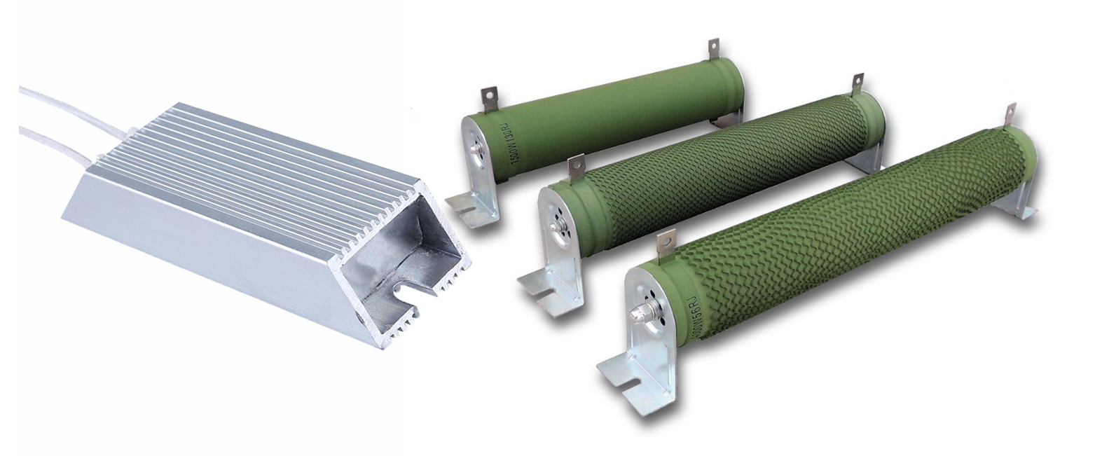
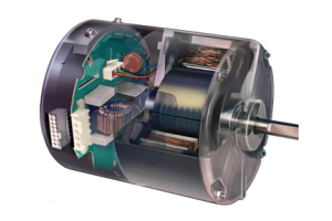
Figure 1. Braking Resistors
What is a Braking Resistor?
A braking resistor is an electrical component used in motor drive systems to control excess energy during motor deceleration. Its main purpose is to safely absorb electrical energy that cannot be sent back to the power supply. The braking resistor helps prevent unstable voltage levels inside the drive system. It is commonly used with variable frequency drives and servo drives. By converting electrical energy into heat, it supports stable and controlled motor operation.
Working Principle of a Braking Resistor
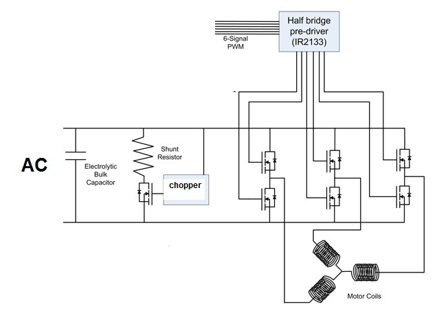
Figure 2. Braking Resistor Working Principle Diagram
When a motor slows down, it produces regenerative energy because the rotating motor acts like a generator. This energy flows back into the DC bus of the drive system and causes the DC voltage to rise. If the energy is not removed, the voltage can exceed safe limits. The braking system is used to manage this excess energy.
A brake chopper monitors the DC bus voltage and activates when the voltage reaches a set level. Once activated, the brake chopper directs the excess energy to the braking resistor. The braking resistor then dissipates this energy as heat. This process allows the motor to decelerate smoothly while keeping the DC bus voltage within a safe range.
Braking Resistor Specifications and Ratings
|
Specification |
Description |
|
Resistance
Value (Ω) |
Fixed
resistance typically between 1 Ω and 200 Ω |
|
Resistance
Tolerance |
Accuracy
range of ±5% or ±10% |
|
Rated Power
(kW) |
Continuous
power rating from 0.1 kW to 500 kW |
|
Short-Time
Power |
Peak power
handling up to 10× rated power for ≤10 s |
|
Duty Cycle
(%) |
Typical
braking duty cycle of 5%–20% |
|
Energy Rating
(J) |
Energy
absorption capacity from 5,000 J to >10 MJ |
|
Maximum
Surface Temperature |
Maximum
allowed surface temperature of 375 °C–550 °C |
|
Ambient
Temperature Range |
Operating
ambient range of –10 °C to +40 °C |
|
Insulation
Resistance |
Minimum
insulation resistance of ≥100 MΩ at 500 VDC |
|
Dielectric
Strength |
Withstands 2.5–4
kV AC for 1 minute |
|
Voltage
Rating |
Maximum DC
voltage typically 600–1000 VDC |
|
Cooling
Method |
Natural
air convection or forced air cooling |
|
Thermal Time
Constant |
Heating time
constant typically 30–300 s |
|
Mounting
Orientation |
Designed for horizontal
or vertical mounting |
|
Protection
Class |
Enclosure
rating commonly IP20–IP54 |
Braking Resistor Protection Circuit
A braking resistor protection circuit is used to prevent damage caused by abnormal operating conditions. It focuses on controlling heat and electrical stress during braking events.
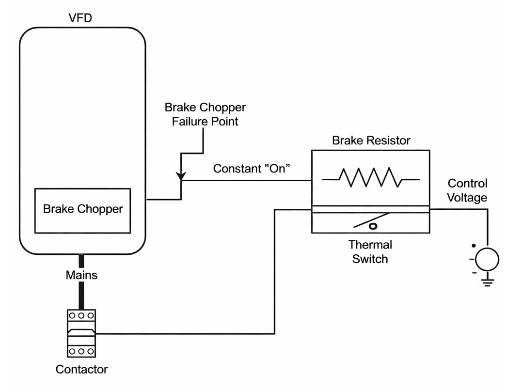
Figure 3. Braking Resistor Protection Circuit
In this configuration, a thermal switch is mounted on the braking resistor body. If the resistor temperature rises beyond a safe limit, the thermal switch opens the control circuit. This action disconnects the braking resistor by opening the main contactor. The protection circuit stops further energy dissipation and prevents overheating.
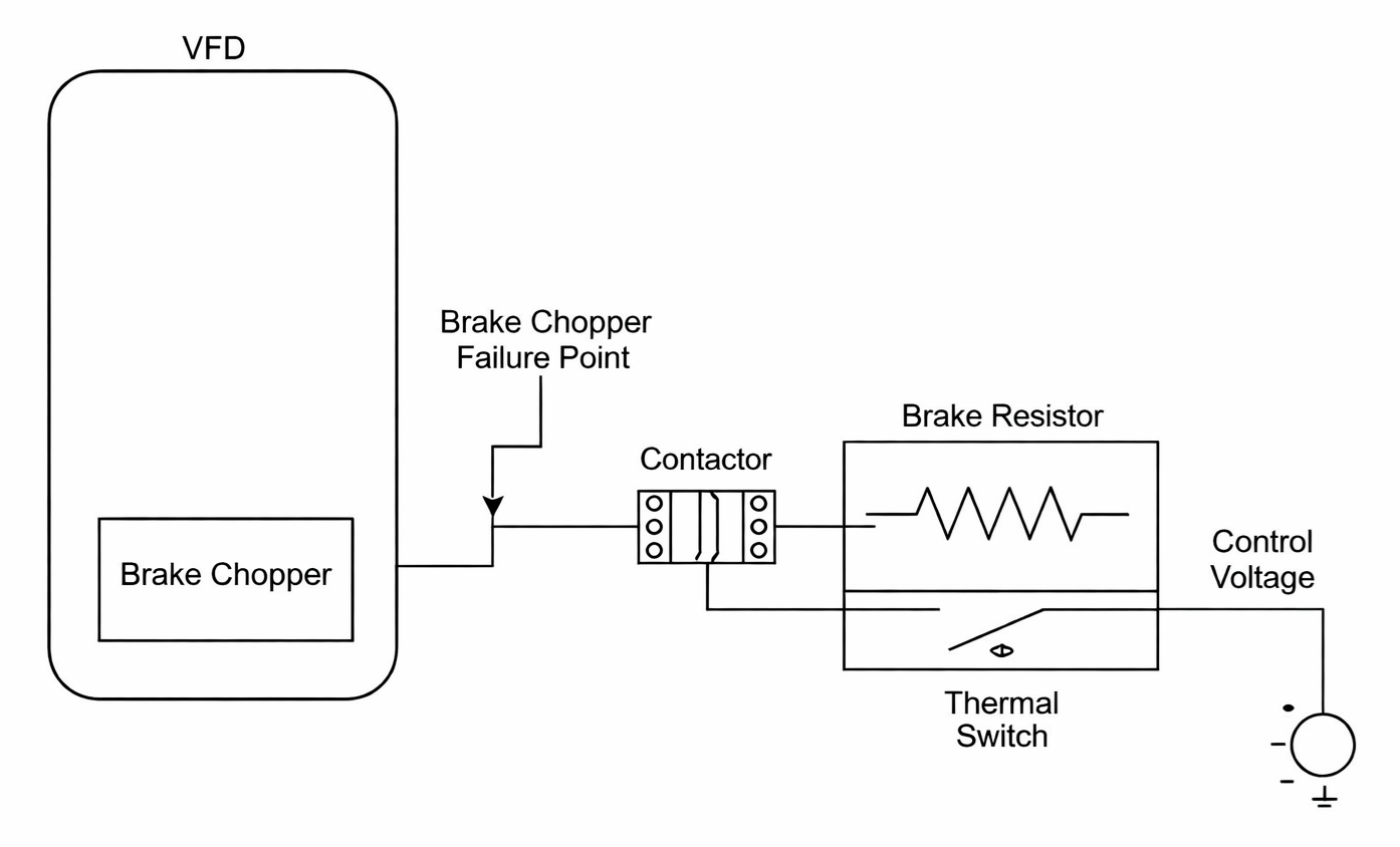
Figure 4. Brake Chopper and Braking Resistor Safety Circuit
This setup adds a contactor between the brake chopper and the braking resistor. If the brake chopper fails and remains continuously active, the contactor isolates the braking resistor. The thermal switch controls the contactor operation using a low-voltage control signal. This design limits thermal stress and protects the resistor from continuous overload.
Types of Braking Resistors
Wire-Wound Braking Resistors

Figure 5. Wire-Wound Braking Resistors
A wire-wound braking resistor uses resistance wire wound around a ceramic or insulated core, as shown in Figure 5. The resistance element is usually exposed or covered with a protective coating to allow heat to escape. Heat is released directly into the air through the resistor surface. This type is often mounted on brackets or frames with open airflow. Compared with enclosed types, wire-wound braking resistors have a visible resistive structure. Their design makes the internal winding easy to identify during inspection.
Aluminum-Housed Braking Resistors
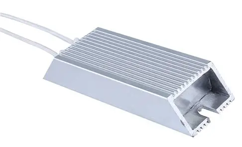
Figure 6. Aluminum-Housed Braking Resistor
An aluminum-housed braking resistor encloses the resistive element inside a solid aluminum body, as shown in Figure 6. The aluminum case acts as both protection and a heat-spreading surface. Heat is transferred from the internal element to the outer housing and released by convection. These resistors have a compact, rectangular form factor. Compared to open wire-wound types, the enclosure provides a cleaner and more sealed appearance.
Grid (Stainless Steel) Braking Resistors
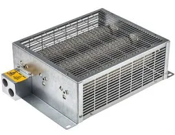
Figure 7. Grid-Type Stainless Steel Braking Resistor
A grid braking resistor is built using stacked stainless steel resistor grids mounted in a metal frame, as shown in Figure 7. The grid structure creates a large surface area for heat release. Air flows freely through the open grid design to carry heat away. This construction allows the resistor to handle large amounts of dissipated energy. Compared with enclosed designs, grid braking resistors are physically larger and more open. Their structure is clearly visible from the outside.
Resistance Test of a Brake Resistor
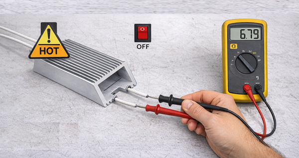
Figure 8. Brake Resistor Resistance Test Using Multimeter
Step 1: Power Isolation
Ensure the drive system is completely powered off. Disconnect the braking resistor from the drive terminals. This prevents incorrect readings and improves safety.
Step 2: Meter Setup
Set a digital multimeter to resistance (Ω) mode. Select a range suitable for the resistor’s expected value. Confirm the meter probes are working correctly.
Step 3: Resistance Measurement
Place the probes on the braking resistor terminals. Hold the probes steady to get a stable reading. Observe the resistance value displayed on the meter.
Step 4: Basic Pass/Fail Check
Compare the measured value to the resistor’s rated resistance. A stable reading close to the rated value indicates a pass. An open circuit or extreme deviation indicates a fail.
Typical Brake Resistor Failures
Brake resistors can fail due to electrical or thermal stress over time. These failures often show visible signs or trigger drive-related warnings.
• Open Circuit Failure
The resistive element may break internally, resulting in no continuity. The drive may report braking faults or overvoltage alarms. The resistor shows infinite resistance when measured.
• Overheating Damage
Excess heat can discolor the resistor body or deform the housing. Surface coatings may crack or peel. The drive may limit braking operation.
• Insulation Breakdown
Internal insulation may degrade, causing leakage paths. This can trigger ground fault warnings. Physical signs may include burn marks or carbon tracking.
• Terminal or Connection Failure
Loose or damaged terminals interrupt current flow. The resistor may appear intact but stop functioning. Drive alarms often appear during deceleration.
Applications of Braking Resistors
1. Variable Frequency Drive (VFD) Systems
Braking resistors are used to manage energy during motor slowdown. They help maintain stable DC bus voltage. This improves stopping control.
2. Cranes and Hoists
These systems generate high braking energy when lowering loads. Braking resistors absorb this energy safely. They support smooth and controlled motion.
3. Elevators and Escalators
Frequent start-stop operation produces regenerative energy. Braking resistors manage this energy during stopping. This supports consistent ride behavior.
4. Conveyor Systems
Sudden stops and load changes require controlled braking. Braking resistors help dissipate excess energy. They stabilize drive operation.
Braking Resistor vs Regenerative Braking vs Brake Chopper
|
Feature |
Braking
Resistor |
Regenerative
Braking |
Brake
Chopper |
|
Energy Handling
Method |
Converts 100%
of braking energy to heat |
Returns 70–95%
of energy to grid |
Diverts
energy to external resistor |
|
Energy
Recovery (%) |
0% |
70–95% |
0% |
|
System
Efficiency (%) |
60–80% |
85–95% |
70–85% |
|
Heat
Generated (Relative) |
High
(≈100%) |
Low (<30%) |
Medium
(≈80%) |
|
Typical DC
Bus Voltage Range |
600–1000
VDC |
600–1000
VDC |
600–1000
VDC |
|
Additional
Hardware Count |
1
component |
2–4
components |
1
semiconductor module |
|
Response Time |
<10 ms |
20–100 ms |
<5 ms |
|
Continuous
Power Capability |
0.1–500 kW |
Drive-rated
only |
Drive-rated
only |
|
Peak Power
Handling |
Up to 10×
rated (≤10 s) |
Limited by
grid |
Limited by
resistor |
|
Control
Signal Voltage |
None |
400–480
VAC grid sync |
5–15 VDC
gate control |
|
Installation
Space |
0.02–1.5
m² |
0.5–2.0 m² |
Internal
to drive |
|
Cooling
Requirement |
Natural /
forced air |
Minimal |
Indirect
via resistor |
|
Grid
Connection Needed |
No |
Yes
(3-phase) |
No |
|
EMC /
Harmonic Impact |
None |
High (IEEE
519 limits) |
Low |
|
Initial
System Cost (Relative) |
1×
baseline |
3–6×
baseline |
2–3×
baseline |
Conclusion
Braking resistors protect drive systems by safely removing excess energy during deceleration. Correct sizing, proper protection circuits, and the right resistor type ensure reliable operation. Regular testing and understanding failure signs help maintain stable and controlled motor braking.
About us
ALLELCO LIMITED
Read more
Quick inquiry
Please send an inquiry, we will respond immediately.
Frequently Asked Questions [FAQ]
1. What happens if a braking resistor is undersized?
An undersized braking resistor overheats quickly, triggers thermal protection, and can cause frequent drive overvoltage trips.
2. What is the difference between internal and external braking resistors?
Internal braking resistors are built into small drives, while external ones handle higher power and offer better heat dissipation.
3. Can one braking resistor be used for multiple drives?
Yes, but only if designed for shared operation with proper isolation, control logic, and sufficient power rating.
4. Do braking resistors waste energy?
Yes. They dissipate braking energy as heat instead of recovering it, unlike regenerative braking systems.
5. Is a braking resistor required for emergency stopping?
In many systems, yes. It allows rapid deceleration while preventing DC bus overvoltage during emergency stops.
Exploring LT1376IS: Pinout, Features, and Typical Uses
on January 24th
Electronically Commutated Motor (ECM): Working, Types, and Applications
on January 22th
Popular Posts
-

Complex Instruction Set Computers: How They Changed Computing?
on April 18th 147749
-

USB-C Pinout and Features
on April 18th 111916
-

Using Xilinx Unified Simulation Primitives: A Comprehensive Guide to FPGA Design and Simulation
on April 18th 111349
-

Power Supply Voltages in Electronics: Meaning of VCC, VDD, VEE, VSS, and GND
on April 18th 83714
-

RJ45 Connector Guide: Pinout, Wiring, Cable Types, and Uses
on January 1th 79502
-

The Ultimate Guide to Wire Color Codes in Modern Electrical Systems
The way our electrical systems use colors isn’t just for looks. Each wire color now indicates a specific function, making it easier to identify and handle electrical components correctly during ins...on January 1th 66872
-

Quality (Q) Factor: Equations and Applications
The quality factor, or 'Q', is important when checking how well inductors and resonators work in electronic systems that use radio frequencies (RF). 'Q' measures how well a circuit minimizes energy...on January 1th 63005
-

Purge Valve Guide: Function, Symptoms, Testing, and Replacement for Optimal Engine Performance
The purge valve is a key part of a car’s system that helps keep the air clean by managing fuel vapors before they can escape into the atmosphere. This not only helps the environment by reducing pol...on January 1th 62949
-

Achieving Peak Performance with the Maximum Power Transfer Theorem
The Maximum Power Transfer Theorem explains how energy from a source, such as a battery or generator, flows to a connected load. It shows the exact condition where the load receives the most power....on January 1th 54077
-

A23 Battery Specifications and Compatibility
The A23 battery is a small, cylinder-shaped battery with high voltage. Also called 23A, 23AE, or MN21, it runs at 12 volts and much higher than AA or AAA batteries. Its special design make...on January 1th 52091
HOT Part Number
-

BD9B100MUV-E2
Rohm Semiconductor
IC REG BUCK ADJ 1A 16VQFN
UPD70F3539AF5A9-PN7-Q-A
Renesas Electronics America Inc
IC MICROCONTROLLER
18081A621JAT2A
KYOCERA AVX
CAP CER 620PF 100V NP0 1808
FDN340P
onsemi
MOSFET P-CH 20V 2A SUPERSOT3
70231-101
Amphenol ICC (FCI)
CONN RCPT BLADE PWR 8POS EDGE MT
MPSW42RLRAG
onsemi
TRANS NPN 300V 0.5A TO92
MC7824BT
onsemi
IC REG LINEAR 24V 1A TO220AB
AD8009ARZ-REEL
Analog Devices Inc.
IC OPAMP CFA 1 CIRCUIT 8SOIC
LT1815CS5#TRPBF
Analog Devices Inc.
IC OPAMP VFB 1 CIRCUIT TSOT23-5
DG411DYZ
Renesas Electronics America Inc
IC SWITCH SPST-NCX4 35OHM 16SOIC
VFT2060C-M3/4W
Vishay General Semiconductor - Diodes Division
DIODE SCHOTTKY 20A 60V ITO-220AB
TSX562AIYST
STMicroelectronics
IC CMOS 2 CIRCUIT 8MINISO
MR256D08BMA45
Everspin Technologies Inc.
IC RAM 256KBIT PARALLEL 48FBGA
VSC3312YYP-01
Microchip Technology
IC SWITCH 16X16 6.5GBPS 196FCBGA
XC68HC908GP20CFB
Motorola
TSG 8BIT20K FLASH
CSR8811A08-ICXR-R
Qualcomm
IC RF TXRX+MCU BLUETOOTH
MPSW05
onsemi
TRANS NPN 60V 0.5A TO92
1N4055R
Solid State Inc.
DIODE GEN PURP REV 900V 275A DO9 -

ASX342ATSC00XPED0-DP
onsemi
IMAGE SENSOR VGA 1/4 CIS SOC
0433.125NR
Littelfuse Inc.
FUSE BOARD MNT 125MA 125VAC/VDC
1SMA5941BT3G
onsemi
DIODE ZENER 47V 1.5W SMA
DCP010512BP-U/700
Texas Instruments
DC DC CONVERTER 12V 1W
1-1734344-1
TE Connectivity AMP Connectors
CONN D-SUB HD RCPT 15P R/A SLDR
KSD1621STF
onsemi
TRANS NPN 25V 2A SOT89-3
BQ24161RGET
Texas Instruments
IC BATT CHG LI-ION 1CELL 24VQFN
BTA26-600BW
STMicroelectronics
TRIAC ALTERNISTOR 600V 25A TOP3
NCP1239DD65R2G
onsemi
IC OFFLINE SWITCH FLYBACK 7SOIC
TMS320TCI6482BZTZA
Texas Instruments
TMS320 - DIGITAL SIGNAL PROCESSO
BQ20Z90DBTR-V150
Texas Instruments
IC GAS GAUGE LI-ION 30TSSOP
PCMB104T-1R0MT
Susumu
FIXED IND 1UH 18A 3.3 MOHM SMD
CY29942AXCT
Infineon Technologies
IC CLK BUFFER 1:18 200MHZ 32TQFP
CC0402KRX7R9BB561
YAGEO
CAP CER 560PF 50V X7R 0402
STPS20M60SG-TR
STMicroelectronics
DIODE SCHOTTKY 60V 20A D2PAK
AT25010N-10SC-2.7
Microchip Technology
IC EEPROM 1KBIT SPI 3MHZ 8SOIC
04023A1R0CAT4A
KYOCERA AVX
CAP CER 1PF 25V C0G/NP0 0402
ISL6327IRZ
Intersil
SWITCHING CONTROLLER, VOLTAGE-MO -

LQW18AN75NG0ZD
Murata Electronics
FIXED IND
DFA100BA160
SanRex Corporation
DIODE MODULE 1600V 100A
BAR46AFILM
STMicroelectronics
DIODE ARRAY SCHOTTKY 100V SOT23
MAX825SEUK
Analog Devices Inc./Maxim Integrated
IC SUPERVISOR MPU
MMST2222A-7-F
Diodes Incorporated
TRANS NPN 40V 0.6A SOT323
FODM8801AR2
onsemi
OPTOISO 3.75KV TRANS 4-MINI-FLAT
FJV1845FMTF
Fairchild Semiconductor
SMALL SIGNAL BIPOLAR TRANSISTOR,
EVK105RH5R1JW-F
Taiyo Yuden
CAP CER 5.1PF 16V R2H 0402
6651170-3
TE Connectivity AMP Connectors
CONN EDGE DUAL FMALE 4POS 0.508
KSZ8893FQLI-FX
Microchip Technology
IC SWITCH ETH 3PORT 128QFP
170M6340
Eaton - Bussmann Electrical Division
FUSE SQUARE 400A 1.3KVAC RECT
BCM20741A2KFB1G
Broadcom Limited
SINGLE-CHIP BLUETOOTH
MAX3443EASA+
Analog Devices Inc./Maxim Integrated
IC TRANSCEIVER HALF 1/1 8SOIC
GRM0335C1H9R3DA01D
Murata Electronics
CAP CER 9.3PF 50V C0G/NP0 0201
TNY175PN
Power Integrations
11.5 W (85-265 VAC) 15 W (230 VA
742700726
Würth Elektronik
FERRITE CORE 278 OHM SOLID 4MM
DM74S20N
onsemi
IC GATE NAND 2CH 4-INP 14DIP
P4SMA56CA-E3/61
Vishay General Semiconductor - Diodes Division
TVS DIODE 47.8VWM 77VC DO214AC