CD4017BE CMOS Counter Explained: Features, Functionality, and Usage
The CD4017BE counter is a versatile CMOS-based integrated circuit widely used in digital systems for counting and sequencing tasks. With 10 outputs and robust control features, including a Schmitt trigger on its clock input, it ensures precise pulse shaping and stable system performance. Commonly found in applications ranging from digital displays to frequency dividers, the CD4017BE’s reliable and efficient design makes it a valuable component in modern electronics. This article digs into its key features, pin configurations, and practical applications, offering visions of its significance in various technological innovations.Catalog

Understanding CD4017BE Counter
The CD4017BE is a CMOS-based integrated circuit designed for a range of counting and sequencing needs. It features 10 outputs and CP, CR, and INH input terminals, making it well-suited for diverse digital systems. With a Schmitt trigger on its clock input, it manages pulse shaping, accommodating different clock signal transitions. This capability is required for systems where pulse precision is dynamic to prevent errors and maintain accuracy.
A low clock disable signal allows it to increment counts and relay these to the decoding output when the clock progresses. Engineers value its reliability for creating stable systems. Its proficient transition management illustrates its role in contemporary electronics. Widely used in digital displays and sequencing tasks, it highlights the significance of each pulse.
When integrated into practical settings, the counter’s pulse shaping reduces system complexity—showcasing a sophisticated design appreciated for functionality and dependability. In addition, to traditional counting roles, the CD4017BE also shines in innovative applications requiring precision and flexibility.
Replacement and Equivalent
CD4017BE Symbol, Footprint, and Pin Configuration
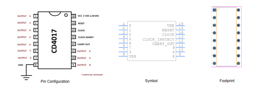
Pins responsible for counting outputs, identified as Q0-Q9 (Pins 1-7, 9-11), deliver key signals but are not sequentially organized. Designers often connect these outputs to LEDs or other indicators, offering real-time feedback in various applications. Circuit diagrams should be consulted to ensure correct connectivity. To prevent complications, outputs should be maintained within their limits.
Power and Ground Connections
• Pin 8 serves as the Vss/Ground, linking to the circuit’s ground, and acting as an active reference for voltage levels. A stable ground connection mitigates potential noise in digital circuits.
• Pin 16, labeled as Vdd/Vcc, acts as the power supply pin, usually connected to a +5V source. Placing a decoupling capacitor near this pin stabilizes the power, reducing voltage fluctuations. This measure aids in maintaining stability, thus preventing erratic chip behavior.
Control and Management Pins
• Pin 12, known as Carry Out, rises high after cycling from 1 to 10, providing a carry-out signal. It facilitates cascading in operations requiring counts beyond 10.
• Clock Enable, assigned to Pin 13, halts the count when high, pausing the operation. This feature proves valuable in synchronizing with external events.
• The clock pin, identified as Pin 14, drives the counting process, advancing the count with each positive pulse. Connections are typically made to external timers or microcontrollers, dominant to the need for precise timing control in digital circuits.
• Pin 15 is the Reset pin, which reinitializes the count sequence to 1. Precision in timing the reset operation ensures the sequence starts as desired, used in automated systems.
CD4017BE Technical Parameters
|
Product Attribute |
Attribute Value |
|
Manufacturer |
Texas
Instruments |
|
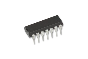
Package
/ Case |
PDIP-16 |
|
Packaging |
Tube |
|
Technology |
CMOS |
|
RoHS
Status |
Non-RoHS
Compliant |
|
Count
Rate |
5.5MHz |
|
Operating
Supply Voltage |
3V ~
18V |
|
Operating
Temperature |
-55°C
~ 125°C |
|
Mounting
Style |
Through
Hole |
|
Counting
Method |
Synchronous |
|
Number
of Bits |
10-bit |
|
Number
of Terminations |
16 |
|
Product
Type |
Counter
ICs |
CD4017BE Features
Balanced Output Performance
The CD4017BE exhibits balanced output performance, delivering steady operation across its ten output states. This uniform behavior suits tasks with intricate sequencing demands, including display systems and LED chasers.
Protection Against Static and Flexible Operation
Designed for resilience, the device withstands static discharge, enhancing its longevity and reliability in diverse environments. It can operate without a clock signal, maintaining logic states in static settings. This flexibility proves useful where energy conservation is emphasized or signal occurrences are rare.
Minimal Power Use
Its low power draw makes the CD4017BE suitable for battery-powered gadgets. It performs well across various voltage ranges (3V-15V), making it adaptable for everything from portable devices to larger systems.
Reset Mechanism
Featuring a reset mechanism, the device can swiftly revert to a known state, easing troubleshooting and supporting stable operation. In sequential logic uses, where timing precision and state retention matter, this feature proves advantageous.
Frequency Division Versatility
The CD4017BE excels in frequency division, managing diverse input pulses to produce ten different output frequencies. Its versatility is valued in digital clocks and counter designs. Leveraging these features requires insightful circuit design to optimize performance, addressing specific needs while considering potential application challenges.
Operational Mechanism
The CD4017BE responds to clock pulses through its CLK pin, with each pulse sequentially activating output pins, creating a cycle of repetitive counting. This process is especially suited for applications like frequency division and sequence counting, where orderly progression is valued.
Clock Pulse Interaction
Clock pulses guide the CD4017BE, igniting a distinct sequence. Each pulse transitions to the subsequent output pin, a cyclical operation central to applications like LED control or timed signal generation. This rhythm echoes the intricacies of timing in practical scenarios.
Application in Frequency Division
The CD4017BE segments clock pulses with finesse, turning a higher frequency into a gentler one. It becomes requisite in crafting specific clock signals for various digital circuits. In sophisticated systems, this synchronization facilitates smooth operation, producing a serene, rhythmic cadence of clock inputs.
Sequence Counting and its Relevance
Sequence counting finds its place within myriad operations. The CD4017BE orchestrates processes demanding precise timing, and harmonizing activities like traffic systems where flow relies on timely intervals. In automation, it elegantly coordinates machinery activation, weaving efficiency into an industrial rhythm.
Diverse Applications of the CD4017BE
Computing Applications
The CD4017BE adeptly manages input pulses in devices like keyboards and mice, enhancing the user interface by ensuring precise data entry and interaction. Counters implemented in these devices boost responsiveness, a serious aspect in domains demanding high precision and speed, such as gaming or graphic design.
Instrumentation Uses
In the world of instrumentation, the CD4017BE assists with measuring aspects like weight and monitoring chemical titration processes. It manages multiple stages for refined sensor readings, leading to precise measurements in laboratories. This accuracy not only strengthens data reliability but also fuels innovative research methods that look to the future.
Electronics Control
When embedded in electronic systems, the CD4017BE oversees operational flow and timing, enhancing functionality in devices like DVD players or AC systems. Ensuring optimal scheduling aids in the development of energy-efficient solutions, reducing power use and prolonging device lifespan, which meets the growing demand for sustainability.
Advancements in Data Processing
Utilizing the CD4017BE in data processing sharpens transmission accuracy and processing rates. Its contribution to system efficiency and stability is evident in networking equipment, where consistent data flow is dominant. By enabling precise signal processing, it supports seamless communication and mitigates risks of data loss or corruption.
Industrial Automation
In industrial environments, the CD4017BE keeps a keen eye on machinery displacement signals, an ultimate factor for controlling precise movements and angles. This application enhances automated assembly lines, where exact positioning boosts productivity and uniformity. It opens doors to sophisticated automation techniques, fostering innovative manufacturing methods and elevating industrial competitiveness.
Pros and Cons
Pros
The counter demonstrates remarkable adaptability, operating efficiently across a wide temperature range from -40℃ to 125℃. Its design includes anti-static protection, enhancing reliability in sensitive contexts. Engineers appreciate its variety of available package options—SOP14, TSSOP14, and DIP14—allowing for seamless integration into multiple circuit designs.
The Johnson counter architecture facilitates high counting speeds, proving to be quite beneficial in digital systems employed in applications like timers and sequencers. This architecture is mostly valued for easing the complexity of intricate timing mechanisms in electronic designs.
Cons
While offering numerous benefits, the counter comes with certain limitations. It lacks a dynamic refresh capability, demanding clock-controlled bit-by-bit refreshing, which could impact performance under specific conditions. The absence of a self-reset mechanism requires manual intervention or external circuitry to reset, adding layers of complication to some designs.
In addition, the counter's range is confined to 10, thus requiring supplementary counters for broader ranges, which may pose challenges in systems with extensive counting needs. Although practitioners often resort to cascading multiple counters to overcome this, it can lead to increased complexity.
Frequently Asked Questions [FAQ]
1. What is CD4017BE used for?
The CD4017BE excels in managing low-range counting tasks, effectively handling counts from 0 to 10. As a Johnson 10-stage decade counter, it simplifies circuit design, making it appealing due to its ability to reduce complexity and conserve space—factors that contribute greatly to design efficiency.
2. What is the input signal type of the CD4017BE counter?
The counter accepts various decimal digital signals. Specifically, clock signals, reset signals, and clock disable signals. This versatility allows for precise control and timing in diverse digital applications, making it suitable for intricate tasks that demand accuracy.
3. What is a Johnson Decade counter?
A Johnson Counter operates using a 5-bit setup composed of D flip-flops, forming a cyclic decade counter. This structure ensures reliable output shifts and predictable sequences, offering substantial advantages in complex sequential logic circuits.
4. What is the operating temperature range of CD4017BE?
Functioning across a wide temperature range from -55°C to 125°C, the CD4017BE demonstrates considerable adaptability. This resilience enhances its performance in various environments, including the harsh conditions commonly found in industrial settings.
5. What is the reset method of CD4017BE counter?
Featuring an asynchronous reset mechanism, any active output is rapidly cleared when the reset signal goes low. This capability allows for quick reinitialization, improving system responsiveness and reliability in ever-changing applications.
About us
ALLELCO LIMITED
Read more
Quick inquiry
Please send an inquiry, we will respond immediately.

Understanding the Differences Between TDA7377 and TDA7388 Amplifiers
on September 29th
LM3900N Quad Operational Amplifier: Working Principle, Equivalents, and Comparison with LM3900DR
on September 29th
Popular Posts
-

Complex Instruction Set Computers: How They Changed Computing?
on April 17th 147711
-

USB-C Pinout and Features
on April 17th 111673
-

Using Xilinx Unified Simulation Primitives: A Comprehensive Guide to FPGA Design and Simulation
on April 17th 111314
-

Power Supply Voltages in Electronics: Meaning of VCC, VDD, VEE, VSS, and GND
on April 17th 83582
-

RJ45 Connector Guide: Pinout, Wiring, Cable Types, and Uses
on January 1th 79227
-

The Ultimate Guide to Wire Color Codes in Modern Electrical Systems
The way our electrical systems use colors isn’t just for looks. Each wire color now indicates a specific function, making it easier to identify and handle electrical components correctly during ins...on January 1th 66752
-

Quality (Q) Factor: Equations and Applications
The quality factor, or 'Q', is important when checking how well inductors and resonators work in electronic systems that use radio frequencies (RF). 'Q' measures how well a circuit minimizes energy...on January 1th 62927
-

Purge Valve Guide: Function, Symptoms, Testing, and Replacement for Optimal Engine Performance
The purge valve is a key part of a car’s system that helps keep the air clean by managing fuel vapors before they can escape into the atmosphere. This not only helps the environment by reducing pol...on January 1th 62798
-

Achieving Peak Performance with the Maximum Power Transfer Theorem
The Maximum Power Transfer Theorem explains how energy from a source, such as a battery or generator, flows to a connected load. It shows the exact condition where the load receives the most power....on January 1th 54020
-

A23 Battery Specifications and Compatibility
The A23 battery is a small, cylinder-shaped battery with high voltage. Also called 23A, 23AE, or MN21, it runs at 12 volts and much higher than AA or AAA batteries. Its special design make...on January 1th 51949
HOT Part Number
-

IR53HD420
Infineon Technologies
IC HALF BRIDGE DRIVER 700MA 9SIP
ISO7730FQDWQ1
Texas Instruments
DGTL ISO 5000VRMS 3CH 16SOIC
MAX7318AUG+T
Analog Devices Inc./Maxim Integrated
IC XPND 400KHZ I2C SMBUS 24TSSOP
TMK063CG101JP-F
Taiyo Yuden
CAP CER 100PF 25V C0G/NP0 0201
VI-272-MX
Vicor Corporation
DC DC CONVERTER 15V 75W
NCP81080MNTBG
onsemi
IC GATE DRVR HALF-BRIDGE 8DFN
P6KE62A
SMC Diode Solutions
TVS DIODE 53VWM 85VC DO15
BZT52C16
Yangjie Technology
SOD-123 16V 0.5W Diodes Zener
AD7416ARM-REEL
Analog Devices Inc.
SENSOR DIGITAL -40C-125C 8MSOP
RT0603BRE07590RL
YAGEO
RES SMD 590 OHM 0.1% 1/10W 0603
GRM1555C1H6R3WZ01D
Murata Electronics
CAP CER 6.3PF 50V C0G/NP0 0402
CD4015BM96
Texas Instruments
IC DUAL STATIC SHFT REG 16-SOIC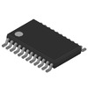
GTLP6C816AMTCX
Fairchild Semiconductor
IC CLK BUF 1:2/1:6 175MZ 24TSSOP
STPS20120CT
STMicroelectronics
DIODE ARRAY SCHOTTKY 120V TO220
BC856AW
Yangjie Technology
SOT-323 PNP 0.2W -0.1A -80V Tra
UCC3913N
Texas Instruments
IC HOT SWAP CTRLR -48V 8DIP
MC100EP16FDT
onsemi
IC RCVR/DRVR ECL DIFF 5V 8TSSOP
2N6394TG
Littelfuse Inc.
SCR 50V 12A TO220AB -
5035662100
Molex
CONN FPC BOTTOM 21POS 0.3MM R/A
BY500-800
Good-Ark Semiconductor
RECTIFIER, FAST RECOVERY, 5.0A,
04026D224KAT2A
KYOCERA AVX
CAP CER 0.22UF 6.3V X5R 0402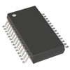
AD9281ARSZRL
Analog Devices Inc.
IC ADC 8BIT PIPELINED 28SSOP
9FGL0841BKILFT
Renesas Electronics America Inc
IC CLOCK GENERATOR 48VFQFP
FDP2D3N10C
Fairchild Semiconductor
N-CHANNEL SHIELDED GATE POWERTRE
TPSMB82A
Littelfuse Inc.
TVS DIODE 70.1VWM 113VC DO214AA
04371.25WR
Littelfuse Inc.
FUSE BOARD MOUNT 1.25A 63VAC/VDC
SI4735-D60-GUR
Skyworks Solutions Inc.
RF RX AM/FM 153KHZ-279KHZ 24SSOP
MAX3646ETG+T
Analog Devices Inc./Maxim Integrated
IC LASER DR 622MBPS 3.63V 24TQFN
2SK3821-DL-E
onsemi
MOSFET N-CH 100V 40A SMP-FD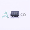
LM78L15ACM
Texas Instruments
IC REG LINEAR 15V 100MA 8SOIC
PIC32MZ1025DAA288-I/4J
Microchip Technology
IC MCU 32BIT 1MB FLASH 288LFBGA
12061C822KAZ2A
KYOCERA AVX
CAP CER 8200PF 100V X7R 1206
NP06DB101M
Taiyo Yuden
FIXED IND 100UH 600MA 680MOHM SM
74HC595DTR2G
onsemi
IC SHIFT REGISTER 8BIT 16TSSOP
A8585KLKTR-T-2
Allegro MicroSystems
IC REG BUCK 5V 2A 10SOIC
ACPL-C87A-500E
Broadcom Limited
IC OPAMP ISOLATION 1 CIRC 8SO -
CFB200-48S48
Cincon Electronics Co. LTD
DC DC CONVERTER 48V 200W
AL3050FDC-7
Diodes Incorporated
IC LED DRVR RGLTR PWM 40MA 6DFN
LA1845NV-TLM-E
Sanyo
SINGLE-CHIP HOME STEREO IC
VE-J64-IZ
Vicor Corporation
DC DC CONVERTER 48V 25W
LM358N
STMicroelectronics
IC OPAMP GP 2 CIRCUIT 8MINI DIP
AZ23C33
Yangjie Technology
SOT-23 33V 0.3W Diodes Zener S
VI-262-IX
Vicor Corporation
DC DC CONVERTER 15V 75W
CD4050BDW
Texas Instruments
IC BUFFER NON-INVERT 18V 16SOIC
CLF12577NIT-680M-D
TDK Corporation
FIXED IND 68UH 2.65A 108MOHM SMD
177919-1
TE Connectivity AMP Connectors
CONN PLATE DBL-LOCK 3POS NATURAL
C1608X7S1A475M080AC
TDK Corporation
CAP CER 4.7UF 10V X7S 0603
PSD854F2-90J
STMicroelectronics
IC FLASH 2M PARALLEL 52PLCC
HMC253ALC4
Analog Devices Inc.
IC RF SWITCH SP8T 3.5GHZ 24CSMT
2KBP04M
onsemi
BRIDGE RECT 1PHASE 400V 2A KBPM
OPB733TR
TT Electronics/Optek Technology
SENSR OPTO TRANS 25.4MM REFL SMD
CC0402JRX7R9BB471
YAGEO
CAP CER 470PF 50V X7R 0402
MAX5354CUA+
Analog Devices Inc./Maxim Integrated
IC DAC 10BIT V-OUT 8UMAX
PB3010-E3/45
Vishay General Semiconductor - Diodes Division
BRIDGE RECT 1P 1KV 30A PB