
Complete Guide to Jumper Wires: Types, Uses, and How to Choose Them
This guide is all about jumper wires, simple wires that let you connect parts of a circuit without using solder. It explains what jumper wires are, what the different wire colors mean, and the types of connectors you can choose from. You'll also learn the difference between solid and stranded wires, how to use special alligator clip wires, and how jumper wires are not the same as big jumper cables used for cars. The guide also shows you how to pick the right jumper wires and where they are commonly used.Catalog
What are Jumper Wires?
Jumper wires are simple, reusable wires used to make temporary electrical connections between different parts of a circuit. Instead of soldering components together, which is permanent, these wires let you easily connect and disconnect points as needed. Because they’re flexible and don’t require tools to connect, they make it easy to try different setups, fix issues, and test new ideas quickly.
Jumper wires also help avoid the heat damage that can come from soldering, which protects sensitive parts. In more advanced environments, they’re used to build quick prototypes or simulate how a circuit will behave before committing to a printed circuit board (PCB). You can use them to inject signals, check if parts are working, or temporarily bypass sections of a circuit. They are good for fast development and experimentation in electronics.
Jumper Wire Colors
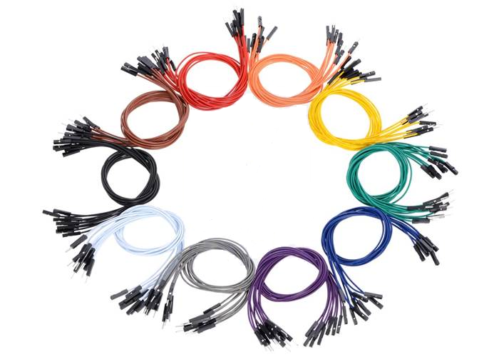
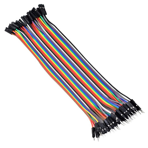
Figure 2. Jumper Wire Colors
The colors of jumper wire insulation help organize and identify connections. These colors follow common conventions:
• Red (Vcc or Power Supply)
Red wires are commonly used to indicate a connection to a positive voltage source. This could be +5V, +3.3V, or any other designated power rail in a circuit. By using red for power, it becomes instantly recognizable, reducing the risk of accidentally connecting it where a ground or signal should go, an error that could damage components or cause malfunction.
• Black (GND)
Black wires are nearly universally understood to represent ground connections. Ground is the reference point in a circuit from which voltages are measured, and it's important for completing electrical loops. Keeping ground wires consistent and clearly marked in black helps ensure safe and accurate wiring.
• Yellow/Green/White/Blue (Signal or Control Lines)
These colors are reserved for signal paths, wires that carry data, sensor readings, or control instructions between components. Yellow often signifies analog signals or communication lines such as I2C (SCL) or SPI. Green may indicate digital control or logic signals (such as Arduino digital output pins). White and blue can serve flexible purposes, often used where multiple signal lines need to be distinguished from each other. White is frequently chosen for clock signals or secondary communication lines, while blue may denote low-priority or auxiliary signals.
Using color-coded wires helps avoid confusion, especially in crowded or complex circuits. It makes it easier to spot mistakes, share diagrams, and troubleshoot in groups or classroom settings. Keeping a consistent color scheme also helps keep wires organized and reduces mental fatigue during debugging.
Types of Jumper Wires
Jumper wires are important components in prototyping and circuit design, allowing for temporary and flexible connections between different parts of a circuit. They come in three main connection types, each suited for specific applications:
1. Male to Male (M-M)
These jumper wires have solid pins, or “male” connectors, on both ends. They are primarily used to connect two female headers, such as those found on breadboards or microcontroller boards (like Arduino). The solid metal tips are typically 0.1 inch (2.54 mm) in diameter, which matches the spacing of standard breadboard and header sockets. This type is useful when building circuits directly on a breadboard, as the pins fit snugly into the breadboard sockets, ensuring a stable connection. M-M jumper wires are ideal for quickly testing circuit designs without soldering. The wires in the figure below are joined together in a flat ribbon. This keeps them organized and makes it easier to follow which wire goes where. Many use them to build circuits quickly and change things easily during testing or learning. You can plug and unplug them as needed without tools.

Figure 3. Male to Male Jumper Wire
2. Male to Female (M-F)
The jumper wires shown in Figure 4 are of the Male to Female (M-F) type. Each wire features a male pin on one end and a female socket on the other, making them ideal for connecting components with male header pins such as sensors, modules, or microcontroller boards to other parts of a circuit. The male end is designed to plug into a breadboard or header on a development board, while the female end securely connects to exposed pins on another device or module. These M-F jumper wires offer excellent versatility, especially when interfacing with external peripherals in prototyping and circuit testing.
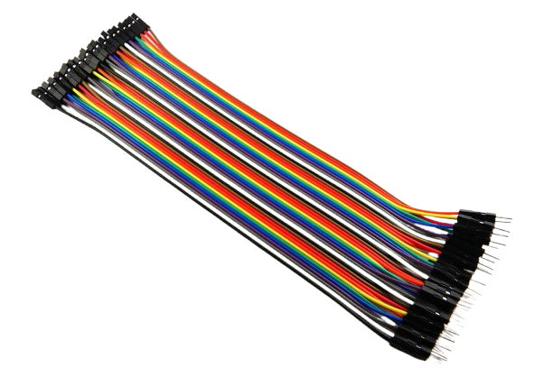
Figure 4. Male to Female Jumper Wire
3. Female to Female (F-F)
Female to Female (F-F) jumper wires feature socket connectors on both ends. F-F jumper wires are used in prototyping and electronic development environments. They allow for quick and reliable connections between development boards such as the Raspberry Pi, Arduino, or other microcontroller platforms and external components like sensors, displays, or modules that expose male pin headers. This eliminates the need for soldering, which can be advantageous when testing circuits or reconfiguring setups frequently. Each wire in the bundle is color-coded, which helps with organization and traceability during circuit design and debugging. The female connectors at each end fit snugly over standard 0.1-inch (2.54 mm) pitch male headers, ensuring a secure and consistent electrical connection.

Figure 5. Female to Female Jumper Wire
Connector Head Types
The ends of jumper wires, which connect different parts of a circuit, can come in different shapes. These shapes are important because they affect how well the wires fit and stay in place. Here are the two most common types:
1. Square Heads
These have a flat, square shape. They fit snugly into breadboards (a tool used to build circuits without soldering) or pin headers (small rows of metal pins). Because they fit tightly, square heads are great for making neat, secure connections. They are useful in tight spaces or in projects that move around a lot, like robots, where wires need to stay firmly in place.
2. Round Heads
These ends are round and don’t fit as tightly as square ones. However, they can be easier to use in unusual or homemade setups, where the holes might not be the same size. Round heads give you more flexibility when building your circuit, especially if you’re trying something new or working with parts that aren’t standard.

Figure 6. Connector Square Heads and Round Heads
Jumper Wires with Alligator Clips
Alligator clip jumper wires are a unique type of connector often used in electronics. Unlike standard jumper wires that have pin or socket ends, these feature metal clips resembling tiny crocodile jaws, hence the name “alligator clips.” The clips have serrated teeth that allow them to grip firmly onto various components. They don't require any special sockets or connectors to function. Simply open the clip, attach it to a wire, terminal, or any exposed metal part of a circuit, and it's ready to use.
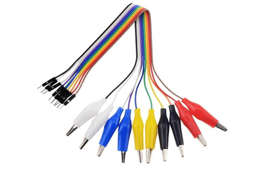
Figure 7. Alligator Clip Jumper Wires
These wires are useful for quick experiments or temporary setups. For instance, if you’re testing a solar panel or trying to make a quick battery connection and don’t have the right socket handy, alligator clips can clamp onto the necessary contact points with ease. They’re also great for attaching to screws, metal pads, or bare wire ends. While they might not offer the neatest connection, they’re perfect when speed and convenience matter like in prototyping or testing phases. The wires often come in different colors (such as red, black, or yellow), making it easier to track your connections.
Solid vs. Stranded Core Jumper Wires
Jumper wires are available in two primary types, solid core and stranded core, each offering distinct advantages based on how they handle, bend, and endure in various projects. Understanding when to use each can lead to neater, more reliable circuits and minimize potential headaches.
Solid core wires consist of a single, rigid conductor that holds its shape when bent, making them ideal for breadboarding. Their stiffness helps maintain tidy, organized layouts, which simplifies tracing connections and debugging. This rigidity, however, can also be a drawback. Frequent bending or sharp angles may weaken the wire and cause it to break, especially near the ends. As a result, solid core wires aren’t the best choice for circuits that need to move or endure constant handling.
On the other hand, stranded core wires are made from many thin strands of wire twisted together, offering superior flexibility. This makes them suitable for applications involving movement, such as robotics, wearables, or mobile devices. They withstand frequent bending and are easier to work with in confined or dynamic environments. However, their soft, flexible ends can fray or splay if not properly prepared, which may complicate insertion into breadboards.
Jumper Wires vs. Jumper Cables
Despite their similar names, jumper wires and jumper cables are designed for entirely different uses and electrical demands. Knowing the difference is needed for both safety and proper function in electronic and automotive contexts.
Jumper wires are slim, insulated wires used in low-power electronic circuits, especially during prototyping. They’re designed to handle low voltage and small currents, ideal for connecting components like breadboards, sensors, and microcontrollers. Often color-coded (red for power, black for ground, and other colors for signals), these wires help keep wiring organized and easy to debug. They come in male-to-male, male-to-female, and female-to-female configurations, making quick, solderless connections simple.
In contrast, jumper cables are thick, rugged wires built for high-current tasks, such as jump-starting car batteries. With heavy insulation and large alligator clips at each end, they’re made to endure high heat, rough handling, and intense electrical loads. Using them on delicate electronics could cause serious damage, just as using lightweight jumper wires in automotive settings could lead to overheating or even fire.
Using the wrong type of wire can be hazardous. Always select the right connector based on the voltage and current needs of your specific application.
Choosing and Using Jumper Wires
When picking jumper wires, consider:
• Core Type
When choosing jumper wires, one of the first things to consider is the core type, solid or stranded. Solid core wires consist of a single piece of metal and are valued for their rigidity. They hold their shape when bent, which makes them perfect for breadboards and other stable setups. However, they become brittle over time and can break if bent repeatedly. On the other hand, stranded core wires are made of many thin strands twisted together, giving them much more flexibility. This makes them ideal for applications where the wires need to move frequently, such as in robotics, wearables, or test setups that change often. Selecting the correct core type ensures both the durability and functionality of your circuit over time.
• Wire Gauge
The gauge of a jumper wire refers to its thickness, and it plays a role in how well the wire handles electrical current. Wire gauge is measured in AWG (American Wire Gauge), where a lower number means a thicker wire. For instance, 22 AWG is thicker and can carry more current than 30 AWG. Thicker wires are best suited for high-current tasks like powering motors or running main power lines, as they reduce the risk of voltage drop and overheating. Thinner wires, such as 28–30 AWG, are more appropriate for signal lines and low-power connections between microcontrollers, sensors, or chips. Matching the wire gauge to your circuit’s electrical demands helps maintain safe and efficient operation.
• Connector Type
Jumper wires are available with a variety of connector types, and selecting the right one is key to building a reliable circuit. The most common connector ends include male pins, female sockets, and alligator clips. Male-to-male (M-M) wires are used to connect two female headers, such as from a breadboard to an Arduino. Male-to-female (M-F) wires are useful when connecting a board to a sensor or module that has male pins. Female-to-female (F-F) wires come in handy when both devices you’re connecting have male headers. Meanwhile, alligator clips are best for quick tests, temporary setups, or connecting to irregular terminals like screws or bare wires. Choosing the right connectors prevents frustrating mismatches and ensures a snug, dependable fit in your circuit.
• Color Coding
Using color-coded jumper wires is a simple yet powerful way to bring clarity to your circuit design. Though the wire color has no impact on electrical function, maintaining a consistent color scheme helps identify connections at a glance. A common convention is to use red for power, black for ground, and other colors for signal or data lines. Sticking to this practice reduces the likelihood of wiring errors, especially in large or complex circuits. It also makes debugging faster and more intuitive, whether you're working solo, teaching others, or sharing your project. Clear color coding turns a tangle of wires into an understandable map of your circuit.
• Bundling and Labeling
As your projects become more complex, wire management becomes increasingly important. Unorganized jumper wires can lead to confusion, accidental disconnects, and time-consuming troubleshooting. Bundling wires with zip ties, twist ties, or braided sleeves helps keep everything tidy and reduces the risk of pulling out the wrong connection. For even better clarity, label wires or groups of wires using masking tape, shrink tubing, or pre-printed tags to indicate their purpose or destination. Organized, labeled wires don’t just look cleaner, they save time and frustration when making changes or tracking down problems later. A small effort in cable management pays off in big ways during debugging and upgrades.
• Checking and Testing Connections
Even when everything looks connected properly, it’s important to test your jumper wires to ensure your circuit is functioning reliably. Loose, damaged, or poorly seated wires can lead to intermittent issues or complete failure. Using a multimeter, you can perform continuity tests to confirm that current is flowing between two points without interruption. This is important after you’ve moved components or adjusted connections on a breadboard. Regularly checking connections can save hours of troubleshooting by catching small issues early. Making this a habit ensures your circuit stays stable, responsive, and easy to maintain.
Application of Jumper Wires
Breadboarding
Jumper wires are important for building and modifying circuits on breadboards. They provide temporary, solder-free connections between components to quickly assemble prototypes and test ideas. This flexibility is useful during the development phase, where designs often change. Jumper wires come in various lengths and connector types, making it easy to route signals cleanly and avoid overcrowding the board.
Connecting Components
Jumper wires are used to connect various electronic components in a circuit. Whether linking sensors to microcontrollers or connecting displays to power sources, jumper wires serve as bridges that carry signals and power between parts. They are helpful when components have different pin layouts or when adapting female-to-male or male-to-male connections, which are common in prototyping and DIY electronics.
Testing and Debugging
Jumper wires are commonly applied in testing and debugging circuits. Many use them to create temporary connections for probing signals, bypassing faulty sections, or rerouting current. This makes it easy to isolate issues and validate changes without permanent modifications. For example, jumper wires can connect test points to diagnostic tools like multimeters or oscilloscopes, providing valuable data during troubleshooting.
Robotics and Motion Systems
Jumper wires are frequently used in robotics to connect control boards with motors, sensors, and actuators. They allow for flexible routing of signals in systems where components may move or shift. Stranded jumper wires, in particular, are suited for dynamic parts that bend or vibrate. In robotic arms or mobile bots, jumper wires simplify setup and enable quick adjustments during iterative development.
Interfacing Multiple Boards
When working with multiple circuit boards, jumper wires are used to establish custom connections between them. They help align mismatched pin headers, handle logic level differences, and transmit data signals (like I2C, SPI, or UART) across boards. This makes jumper wires important in multi-board setups where off-the-shelf connectors don’t always match the project’s layout.
Sensor Prototyping
Jumper wires are applied in sensor prototyping to connect sensor modules to microcontrollers or breadboards. They provide dedicated lines for power (VCC, GND) and signal, allowing to easily swap out different sensors during testing. This helps compare accuracy, responsiveness, and compatibility before choosing a final sensor for design.
Conclusion
Jumper wires make it easy to build and test circuits without permanent connections. They are reusable, come in many colors to help keep things organized, and have different connector types to match your parts. Solid wires are better for stable setups, while flexible (stranded) wires work well in moving or changing systems. Jumper wires are great for linking sensors, fixing problems, or connecting boards. They are simple tools, but very useful in electronics projects of all kinds.
About us
ALLELCO LIMITED
Read more
Quick inquiry
Please send an inquiry, we will respond immediately.
Frequently Asked Questions [FAQ]
1. How many volts can jumper wires handle?
Most jumper wires used in electronics can safely handle up to 30 volts DC, though they’re usually used for much lower voltages like 3.3V, 5V, or 12V. These are common in Arduino or Raspberry Pi projects. While the wire might handle higher voltages, the insulation and small spacing between wires make it risky to go beyond this range. Using jumper wires for anything over 30V can lead to short circuits or melting insulation, so it’s best to stick to low-voltage circuits.
2. How to connect a jumper wire?
To connect a jumper wire, just plug each end into the correct place, one into a pin, socket, or breadboard hole, and the other where it needs to go in the circuit. You don’t need any tools. Make sure the wire fits tightly so it doesn’t fall out. Use the right type (male or female) depending on the pin or hole. Also, using color-coded wires (like red for power, black for ground) makes it easier to stay organized and avoid mistakes.
3. Where should you never use a jumper wire?
You should never use jumper wires in high-voltage or high-power situations, like in car batteries or home wiring. Jumper wires are made for small, low-voltage circuits only. Also avoid using them in wet or outdoor places. They’re not meant for long-term use either, only for testing and temporary setups. Using them the wrong way can cause overheating, electrical failure, or even a fire.
4. What gauge is jumper wire?
Most jumper wires are 22 AWG, which is a good size for breadboards and small circuits. This size can carry small amounts of current and still fit into standard holes and headers. Some thinner wires, like 28–30 AWG, are used for signals, while 20 AWG might be used for a little more power. Thicker wires carry more current but might not fit well, and thinner wires are best for light signals only.
5. What is the purpose of a jumper wire when making electrical tests?
Jumper wires are used in testing to quickly connect different parts of a circuit without soldering. They let you try different setups, test signals, or connect tools like multimeters or oscilloscopes. You can also use them to temporarily fix or bypass parts of a circuit. This makes it easier to find problems and check if your design is working before making anything permanent.
Why Choose the LFX125EB-03FN256I for Your Project
on May 26th
EPM3128ATC100-5 CPLD Guide: Features, Applications, Alternatives and Datasheet
on May 22th
Popular Posts
-

Complex Instruction Set Computers: How They Changed Computing?
on June 11th 148369
-

USB-C Pinout and Features
on June 11th 131089
-

Using Xilinx Unified Simulation Primitives: A Comprehensive Guide to FPGA Design and Simulation
on June 11th 111849
-

Power Supply Voltages in Electronics: Meaning of VCC, VDD, VEE, VSS, and GND
on June 11th 94098
-

RJ45 Connector Guide: Pinout, Wiring, Cable Types, and Uses
on January 1th 93471
-

The Ultimate Guide to Wire Color Codes in Modern Electrical Systems
The way our electrical systems use colors isn’t just for looks. Each wire color now indicates a specific function, making it easier to identify and handle electrical components correctly during ins...on January 1th 76627
-

Quality (Q) Factor: Equations and Applications
The quality factor, or 'Q', is important when checking how well inductors and resonators work in electronic systems that use radio frequencies (RF). 'Q' measures how well a circuit minimizes energy...on January 1th 74625
-

Purge Valve Guide: Function, Symptoms, Testing, and Replacement for Optimal Engine Performance
The purge valve is a key part of a car’s system that helps keep the air clean by managing fuel vapors before they can escape into the atmosphere. This not only helps the environment by reducing pol...on January 1th 68562
-
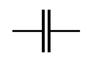
Understanding Capacitors and Their Symbols in Circuit Diagrams
Capacitors are small parts used in almost all electronic devices. They store and release electrical energy and are found in things like power supplies, radios, and circuits that help reduce noise. ...on June 11th 58353
-

A23 Battery Specifications and Compatibility
The A23 battery is a small, cylinder-shaped battery with high voltage. Also called 23A, 23AE, or MN21, it runs at 12 volts and much higher than AA or AAA batteries. Its special design make...on January 1th 57907
HOT Part Number
-

MGA-634P8-TR1G
Broadcom Limited
IC AMP CDMA 1.5GHZ-2.3GHZ 8QFN
AD8276BRMZ-R7
Analog Devices Inc.
IC OPAMP DIFF 1 CIRCUIT 8MSOP
RK73H2BTTD4420F
KOA Speer Electronics, Inc.
RES 442 OHM 1% 1/4W 1206
12105G106ZAT2A
KYOCERA AVX
CAP CER 10UF 50V Y5V 1210
8SLVP1204ANLGI/W
Renesas Electronics America Inc
IC CLK BUFFER 2:4 2GHZ 16VFQFN
VI-J11-EX
Vicor Corporation
DC DC CONVERTER 12V 75W
MM74C04M
onsemi
IC INVERTER 6CH 1-INP 14SOIC
THVD1420DR
Texas Instruments
3.3-V TO 5-V RS-485 TRANSCEIVER
MPXY8600DK6T1
NXP USA Inc.
RF TX IC FSK 315/434MHZ 32QFN
LTC2402IMS#PBF
Analog Devices Inc.
IC ADC 24BIT SIGMA-DELTA 10MSOP
HCPL-314J-500E
Broadcom Limited
OPTOISO 5KV 2CH GATE DRIVER 16SO
MIC5504-3.3YM5-T5
Microchip Technology
IC REG LINEAR 3.3V 300MA SOT23-5
XC4013XL-2BG256C
AMD
IC FPGA 192 I/O 256BGA
71M6534H-IGT/F
Analog Devices Inc./Maxim Integrated
IC ENERY METER 3PH 256K 120-LQFP
IRFS52N15DTRLP
Infineon Technologies
MOSFET N-CH 150V 51A D2PAK
0805ZC104KAT9A
KYOCERA AVX
CAP CER 0.1UF 10V X7R 0805
SIS444DN-T1-GE3
Vishay Siliconix
MOSFET N-CH 30V 35A PPAK1212-8
87972DYI-147LFT
Renesas Electronics America Inc
IC CLOCK MULTIPLIER 52TQFP -

2N6351
Microchip Technology
TRANS NPN DARL 150V 5A TO33
LCMXO256C-4M100C
Lattice Semiconductor Corporation
IC FPGA 78 I/O 100CSBGA
301A10059X
Conec
CONN D-SUB PLUG 25POS SLDR CUP
IPA60R520CP
Infineon Technologies
N-CHANNEL POWER MOSFET
WM8510GEDS/RV
Cirrus Logic Inc.
IC CODEC MONO SPEAKER DVR 28SSOP
0805CS-240EJTS
Delta Electronics/Components
FIXED IND 24NH 500MA 220MOHM SMD
SML-D12V8WT86
Rohm Semiconductor
LED RED DIFFUSED 0603 SMD
MM3Z13VST1G
onsemi
DIODE ZENER 13V 300MW SOD323
FAN53600AUC33X
onsemi
IC REG BUCK 3.3V 600MA 6WLCSP
AD8602ARZ-REEL7
Analog Devices Inc.
IC CMOS 2 CIRCUIT 8SOIC
EP3C40F484C6N
Intel
IC FPGA 331 I/O 484FBGA
S-8352A33MC-K2ST2G
ABLIC Inc.
IC REG CTRLR BOOST SOT23-5
S30460
Microchip Technology
RECTIFIER
NB100LVEP56DTR2G
onsemi
IC DIFF DIG MULTPL 2X2:1 20TSSOP
SI9114ADY-T1-E3
Vishay Siliconix
IC REG CTRLR MULT TOP 14SOIC
SI4896DY-T1-E3
Vishay Siliconix
MOSFET N-CH 80V 6.7A 8SO
FOD250L
onsemi
OPTOISO 5KV TRANS W/BASE 8DIP
BD4836G-TR
Rohm Semiconductor
IC SUPERVISOR 1 CHANNEL 5SSOP -
KSZ8721BL
Microchip Technology
IC TRANSCEIVER FULL 1/1 48LQFP
RT9011-MSGJ6
Richtek USA Inc.
IC REG LINEAR 2.8V/3.3V TSOT23-6
SN65HVD485ED
Texas Instruments
IC TRANSCEIVER HALF 1/1 8SOIC
VI-2N4-CU
Vicor Corporation
DC DC CONVERTER 48V 200W
UC2844AD
Texas Instruments
IC CUR-MODE PWM CONT 14-SOIC
STM32F072C8T7
STMicroelectronics
IC MCU 32BIT 64KB FLASH 48LQFP
1206L035/16YR
Littelfuse Inc.
PTC RESET FUSE 16V 350MA 1206
AD8553ARMZ-REEL
Analog Devices Inc.
IC INST AMP 1 CIRCUIT 10MSOP
MSP430F5310IRGCR
Texas Instruments
IC MCU 16BIT 32KB FLASH 64VQFN
SMAJ12A-E3/5A
Vishay General Semiconductor - Diodes Division
TVS DIODE 12VWM 19.9VC DO214AC
MOC3032VM
Fairchild Semiconductor
TRIAC OUTPUT OPTOCOUPLER WITH ZE
MT47H64M16HR-187E:H
Micron Technology Inc.
IC DRAM 1GBIT PAR 84FBGA
CY22393FXIT
Infineon Technologies
IC CLOCK GENERATOR 16TSSOP
MBR2535CT
Vishay General Semiconductor - Diodes Division
DIODE ARRAY SCHOTTKY 35V TO220AB
06035A101JA12A
KYOCERA AVX
CAP CER 100PF 50V C0G/NP0 0603
LM431ACMX
onsemi
IC VREF SHUNT ADJ 2% 8SOIC
HMC175MS8TR
Analog Devices Inc.
IC DOUBLER PASSIVE FREQ 8MSOP
TL072CDG4
Texas Instruments
IC OPAMP JFET 2 CIRCUIT 8SOIC