Comprehensive Guide to Electrical Continuity Testing: Tools, Techniques, and Applications
Electrical continuity testing is a key check-up to make sure electricity can freely flow through circuits and components like those found in everyday gadgets and big industrial machines. This detailed guide dives into why electrical continuity testing is important, how it's done, and the main tools used, such as multimeters and continuity testers. By explaining the testing steps and their uses in keeping systems running smoothly and safely, this article aims to show how important this testing is to prevent failures and make sure electrical setups work well.Catalog

Overview of Electrical Continuity Testing Description
Electrical continuity testing is a diagnostic technique used to verify whether an electrical circuit or component can allow the uninterrupted flow of current. This test assesses the completeness of a circuit, ensuring that electricity can travel through it without encountering breaks or faults. The process involves the use of specialized tools such as multimeters or continuity testers, which introduce a small current or voltage into the circuit and monitor its behavior. A complete circuit, where the current flows without interruption, is considered "continuous," while any disruption caused by a break, loose connection, or fault indicates a loss of continuity. This technique is useful for determining the operational integrity of various electrical components, such as switches, fuses, wires, and connections. Continuity testing is often represented in electrical schematics by specific symbols, allowing technicians to easily identify points for inspection. This straightforward and non-invasive method is used in both simple and complex electrical systems, as it provides immediate feedback on whether a circuit is functioning as intended. Overall, electrical continuity testing serves as the first step in identifying and resolving issues within electrical systems, making it a core of effective maintenance and troubleshooting practices.
Purpose of Electrical Continuity Testing
The primary purpose of electrical continuity testing is to ensure the reliability and functionality of electrical circuits and components. By determining whether a circuit allows the uninterrupted flow of current, this test helps identify issues like breaks, loose connections, or faulty components that could compromise the system’s performance. Continuity testing plays a role in routine maintenance by verifying the integrity of electrical systems, ensuring that they are capable of operating as designed. Additionally, it helps prevent larger issues by detecting potential faults early, avoiding costly repairs, equipment damage, or even hazardous situations like electrical fires. In troubleshooting scenarios, continuity testing simplifies the diagnostic process by pinpointing the exact location of a problem, allowing to focus on specific areas rather than performing extensive inspections. It also ensures safety during electrical repairs by confirming that circuits are properly de-energized before any work begins. In manufacturing and quality control settings, continuity testing is used to verify that newly built electrical components meet performance standards. The purpose of continuity testing extends beyond simply identifying faults, it also ensures system reliability, improves safety, and reduces downtime in both residential and industrial applications.
Importance of Electrical Continuity Testing in Maintenance and Troubleshooting
Electrical continuity testing is need for the maintenance and troubleshooting of electrical circuits because it ensures the safety, reliability, and efficiency of these systems. Regular maintenance relies heavily on continuity testing to assess the integrity of circuits and identify potential faults before they develop into major issues. By proactively detecting problems like loose connections, corroded wires, or broken components, continuity testing minimizes the risk of unexpected failures that could lead to costly repairs, operational downtime, or safety hazards. During troubleshooting, continuity testing is an important diagnostic tool that helps pinpoint the root cause of a circuit’s malfunction. Rather than replacing multiple components unnecessarily, you can use continuity testing to isolate the exact location of a fault, saving time and resources. Continuity testing enhances electrical safety by verifying that circuits are de-energized before maintenance or repairs begin, reducing the risk of accidental shocks. In complex systems, where multiple circuits interact, continuity testing ensures each individual path is functioning properly, preventing cascading failures. Its importance extends to a wide range of applications, from home electrical repairs to industrial system maintenance.
Overview of Electrical Continuity Tester
A continuity tester is a diagnostic tool designed to check whether an electrical circuit forms a complete and unbroken path. It typically consists of a probe, a testing lead, and an indicator such as a light or a buzzer that activates when the circuit is continuous. This tool plays a role in identifying breaks, loose connections, or faults in wiring, ensuring that electricity can flow uninterrupted between two points. Its simplicity and efficiency make it an invaluable asset working on electrical systems. While it is not designed to measure voltage, resistance, or current, its singular focus on continuity provides a quick, reliable, and safe way to troubleshoot circuit problems. This makes it useful during the repair, assembly, or maintenance of electrical equipment, from home appliances to industrial machinery. Continuity testers are versatile and come in various forms, including pen-style testers and those integrated into multimeters. Despite its basic design, the tool is highly effective and ensures that electrical systems operate safely and efficiently.

Figure 2. Electrical Continuity Tester
Components and Functionality
A continuity tester is a straightforward device composed of a few key components that work together to determine the presence of an unbroken electrical path. The main parts include a probe for contacting one point of the circuit, a test lead (often with an alligator clip) to connect to the other point, and an indicator mechanism such as an LED light or an audible buzzer. When the probes are placed at two ends of a circuit, the tester sends a small, low-current signal through the circuit. If the circuit is complete and has continuity, the signal flows freely, causing the indicator to light up or emit a sound. If the circuit is broken, the tester will remain silent and dark, alerting to a problem. Some models may include additional features like a battery compartment to power the device or overload protection to ensure safety during use. Despite their simplicity, continuity testers are highly effective for pinpointing issues in electrical wiring, switches, fuses, and other components. Their functionality is based entirely on detecting a complete path for current, making them safe, user-friendly, and invaluable for troubleshooting electrical systems quickly and accurately.
How It Differs From Other Testing Equipment?
Continuity testers differ from other electrical testing equipment in terms of purpose, functionality, and complexity. Unlike multimeters, which can measure voltage, resistance, and current, or insulation testers designed to check the integrity of insulating materials, a continuity tester serves a single, focused purpose: identifying whether a circuit is complete or broken. This simplicity allows for faster and more intuitive operation, making it an ideal tool for quick troubleshooting. While devices like clamp meters or voltage testers require a higher level of technical knowledge to interpret readings, a continuity tester provides straightforward feedback, typically in the form of a light or sound, which even beginners can easily understand. Another distinction lies in safety and usability. Continuity testers work with very low currents, reducing the risk of accidental shocks or damage to sensitive electronic components. Their compact and lightweight design enhances portability, allowing for convenient use in tight spaces or on-site repairs. While other testing tools are necessary for more advanced diagnostics and measurements, the continuity tester’s simplicity and efficiency make it a preferred choice for identifying breaks in wiring, checking switches, or verifying connections in a variety of electrical systems.
Overview of Multimeters
A multimeter is a versatile and multifunctional electronic device used to measure a variety of electrical properties, including voltage, current, and resistance. It is an important tool offering precise diagnostics for electrical and electronic systems. Multimeters come in two main types: digital and analog, each catering to specific preferences and applications. One of the most important features of a multimeter is its ability to perform continuity testing, which allows to determine whether an electrical circuit is complete or interrupted. Unlike dedicated continuity testers, multimeters offer the added benefit of measuring other parameters, making them a more comprehensive tool for diagnosing and repairing electrical issues. Whether testing household wiring, automotive circuits, or electronic components, multimeters are prized for their accuracy and versatility. Many modern digital models include additional features such as auto-ranging, data hold, and overload protection, further enhancing their functionality. With a multimeter, you can troubleshoot a wide range of issues, from identifying faulty components to ensuring proper voltage levels in complex systems.

Figure 3. Multimeters
Features to Continuity Testing
Multimeters include several features that make them highly effective for continuity testing, combining the functionality of a dedicated continuity tester with the versatility of additional measurement capabilities. In continuity mode, the multimeter sends a small current through the circuit being tested. If the circuit is complete, it emits an audible beep or displays a reading on the screen, indicating the presence of continuity. This audible feedback is especially useful for hands-free operation in situations where visual confirmation is difficult. Digital multimeters, in particular, excel in continuity testing due to their precision and ease of use. Features such as auto-ranging ensure that the device automatically adjusts to the correct settings, while backlit screens and ergonomic designs make operation straightforward even in challenging environments. Many multimeters also include overload protection to safeguard the device and the circuit being tested. Compared to a standalone continuity tester, the multimeter provides additional context, such as the resistance level of a circuit, which can help diagnose partial continuity or identify weak connections. By integrating continuity testing into a multifunctional tool, multimeters offer convenience, accuracy, and reliability for a broad range of electrical troubleshooting tasks.
Differences Between Digital and Analog Models
Digital and analog multimeters differ in their operation, display, and overall performance, each offering distinct advantages for continuity testing and general electrical diagnostics. Digital multimeters (DMMs) feature a digital screen that provides precise, easy-to-read numerical results. They are often equipped with advanced features such as auto-ranging, continuity beepers, and overload protection, making them highly user-friendly and suitable for a wide range of tasks. Their accuracy and ability to measure low currents or resistance levels make them the preferred choice for professionals. Analog multimeters, on the other hand, use a needle to display readings on a graduated scale. While they may lack some of the advanced features of their digital counterparts, they excel in providing real-time visual feedback, which can be useful for observing trends, such as fluctuating voltage levels. However, analog models can be less precise and more difficult to read, especially for beginners. When it comes to continuity testing, digital multimeters are generally more efficient and easier to use, thanks to their audible indicators and high sensitivity. In contrast, analog models are better suited for tasks that require monitoring gradual changes, offering a more tactile and visual experience.

Figure 4. Digital and Analog Models
Steps to Use a Continuity Tester
Step 1: Check the Tester
Before using a continuity tester, it is important to ensure that the device itself is functioning properly. Start by inspecting the tester for any visible signs of damage or wear, such as frayed wires or loose components. If the tester is battery-powered, check that the battery is charged or has sufficient power to operate. A low battery could cause the tester to give unreliable results or fail to operate altogether. Next, confirm that the device's settings are configured correctly, according to the manufacturer’s instructions. Many testers include a self-test feature or a designated calibration process, use these to verify that the tester is in working condition before proceeding. Taking this preliminary step ensures the accuracy of your readings and prevents misdiagnosis of circuit issues.
Step 2: Identify Testing Points
The next step involves identifying the specific points in the circuit where you intend to test for continuity. These points might include connectors, terminals, switches, or wiring junctions. To do this effectively, consult a circuit diagram or a wiring schematic if available, as it can provide a clear understanding of the circuit layout. This is useful in complex systems with multiple paths and components. Make a plan for systematically testing each point, so you don’t accidentally skip or overlook any part of the circuit. Knowing exactly where to place the test leads minimizes guesswork and ensures that the testing process is efficient and thorough.
Step 3: Apply the Test Leads
Once you have identified the testing points, position the test leads on the designated spots in the circuit. Continuity testers typically have two leads: one red (positive) and one black (negative), which help ensure proper orientation and identification. Carefully attach the leads to the components being tested, making sure they are making solid, stable contact. Loose or improper contact can result in false readings, leading to incorrect conclusions about the state of the circuit. In some cases, you may need to use clamps or probes for a more secure connection, especially if you are working in a tight space or testing multiple components. By applying the leads with precision, you reduce the risk of error and increase the reliability of your test results.
Step 4: Interpret Feedback
After applying the test leads, observe the feedback provided by the continuity tester. Most testers use an audible signal, such as a steady beep, or a visual indicator, like a light or a digital display, to convey whether the circuit is complete. A continuous beep or a lit indicator usually signifies that there is an unbroken electrical path between the test points, indicating proper continuity. Conversely, the absence of a beep, light, or other feedback generally means there is a break in the circuit, such as a damaged wire or a faulty connection. In some advanced testers, the display might provide additional information, like resistance values, to help diagnose the problem further. Carefully note the feedback and, if necessary, double-check the results by retesting the same points to rule out any inconsistencies. Interpreting the feedback correctly is key to identifying whether the circuit is functioning as intended or requires repair.
Continuity Tester Symbol
The continuity tester symbol, an element in electrical schematics acting as a universal shorthand for identifying and testing conductive paths within a circuit. This symbol is represented as an uninterrupted line connecting two points. Sometimes, it may include arrows to indicate the direction of current flow. It’s simple yet effective design allows it to convey information clearly in circuit diagrams where space is limited. The continuity tester symbol marks areas where the continuity of an electrical path needs to be verified, ensuring the circuit functions as intended. The continuity tester symbol is more than just a part of a schematic, it is a practical tool that brings efficiency and clarity to electrical diagnostics and repairs. By using this standardized representation, you can quickly identify points in a circuit that require testing. This speeds up the troubleshooting process, reducing the time spent searching for issues in complex systems. Recognizing this symbol enables you to navigate schematics confidently and without confusion.

Figure 5. Continuity Tester Symbol

Figure 6. Continuity Tester Symbol
Benefits of Standardization
The consistency of the continuity tester symbol across technical documents plays a role in enhancing communication. Because it is a standardized symbol, various industries and regions can easily interpret and understand it. This standardization fosters better collaboration between individuals working on the same project, regardless of location or background. The continuity tester symbol supports accuracy, efficiency, and effective teamwork in electrical work. It’s a small yet powerful element that makes electrical work more accessible and efficient for everyone involved.
What Does the Continuity Symbol on a Multimeter Mean?
The continuity symbol on a multimeter is an important feature that makes testing for circuit integrity both straightforward and accessible. This symbol is represented by either a diode icon or a sound wave icon, clearly indicating the mode specifically designed for continuity tests. By selecting this mode, you enable the multimeter to determine whether an electrical path between two points is intact or broken. This simple yet effective feature is a tool for anyone working with electrical circuits, as it allows them to confirm connectivity with ease and precision.

Figure 7. Continuity Symbol on a Multimeter
When the multimeter is in continuity mode, it provides immediate feedback through either an audible beep or a visual signal on the display whenever it detects a complete electrical path. This instant feedback eliminates the need for guesswork and simplifies troubleshooting by allowing to quickly identify open circuits, broken wires, or faulty connections. The continuity mode is invaluable because it ensures circuits are correctly assembled and free from defects. Additionally, it helps detect potential issues that could compromise safety or lead to equipment malfunctions in both assembly and maintenance processes. In essence, the continuity symbol on a multimeter is more than just a functional icon, it represents a practical and reliable tool for ensuring the integrity and safety of electrical systems.
How to Perform Continuity Tests Using a Multimeter?
Step 1: Set the Multimeter to Continuity Mode
The first step in performing a continuity test using a multimeter is to set the device to continuity mode. Begin by turning the multimeter’s dial to the appropriate setting, which is marked by a diode symbol or a sound wave icon. This mode is designed to check for continuous electrical paths within a circuit and will enable the multimeter to emit an audible beep or provide a visual signal when continuity is detected. Ensuring the multimeter is in the correct mode for obtaining accurate results, as other settings like voltage or resistance may yield misleading information or even damage the multimeter if used improperly during a continuity test.
Step 2: Power Down the Circuit
Before proceeding with the test, it is required to ensure that the circuit being tested is completely powered off. This step is not only good for safety but also protects the multimeter from potential damage caused by live current. Even a small electrical charge in the circuit can interfere with the continuity test and produce inaccurate readings. To power down the circuit, switch off any connected power sources, unplug the device if applicable, and double-check using the multimeter in voltage mode if there is any doubt. Taking the time to confirm the circuit is de-energized is a precaution that ensures safety and the integrity of the testing process.
Step 3: Connect the Test Leads
Once the circuit is powered down, the next step is to properly connect the multimeter’s test leads. Insert the black lead into the "COM" (common) port and the red lead into the port labeled for continuity or resistance testing, which is often marked with an ohm symbol (Ω). Ensuring the test leads are correctly inserted is important for obtaining accurate results and preventing errors. Inspect the leads for any visible damage, such as frayed wires or loose connections, as faulty leads can produce unreliable readings. A secure and proper connection of the test leads to the multimeter is a necessary preparation for the continuity test.
Step 4: Test the Circuit Points
With the multimeter in continuity mode and the leads connected, proceed to test the circuit points where continuity needs to be verified. Place the test leads on the two points you wish to test, ensuring that they make firm and stable contact with the components or wires. If the circuit is intact, the multimeter will emit a continuous beep or display a low resistance value on the screen, indicating an unbroken electrical path. If no beep is heard or if the resistance reading is very high, this suggests that there is a break in the circuit, such as a damaged wire or a loose connection. Be methodical in testing multiple points if needed, and take note of any inconsistencies that might help pinpoint the fault. This step allows to quickly and effectively diagnose circuit issues, enabling to locate and repair faults with confidence.
Common Issues Found Through Continuity Testing
Continuity testing is a method used to diagnose problems in electrical circuits. By using tools like multimeters or continuity testers, you can locate faults that compromise the functionality and safety of electrical systems. This section provides a detailed breakdown of common circuit problems identified through continuity testing and offers step-by-step guidance on how to resolve these issues effectively.
Types of Circuit Faults and Characteristics
1. Open Circuits
An open circuit happens when there is a break or gap that prevents current from flowing through the circuit. This type of fault is caused by broken wires, disconnected components, or damaged parts. Common symptoms of an open circuit include devices that fail to power on or operate, as well as the absence of electrical signals in certain parts of the circuit. Using a continuity tester or multimeter, an open circuit can be identified when there is no audible signal or when infinite resistance is displayed, confirming that current cannot pass through.
2. Short Circuits
A short circuit occurs when two conductive points connect unintentionally, creating a direct path for current to flow. This causes excessive current, which can result in overheating, damage to components, and circuit failure. Symptoms of a short circuit often include frequent tripping of circuit breakers, blown fuses, or the presence of burning odors. Continuity testing can detect a short circuit by showing a continuous beep or abnormally low resistance readings, indicating an unintended connection in the circuit.
3. Loose or Corroded Connections
Loose or corroded connections happen when contact points in the circuit become unstable or damaged by corrosion. These issues interrupt current flow and often cause intermittent operation or erratic device performance. During continuity testing, fluctuating or inconsistent resistance readings may reveal loose or corroded connections. This type of fault can lead to irregular circuit behavior if not addressed promptly.
4. Faulty Components
Components like resistors, capacitors, and switches can fail over time or due to misuse, disrupting the normal operation of a circuit. Faulty components can cause unpredictable behavior in the circuit or total failure. Continuity testing can identify these issues by detecting open or short conditions within individual components, confirming their failure and need for replacement.
5. Grounding Issues
Grounding problems occur when circuits lack proper connections to ground, leading to safety hazards and operational malfunctions. Inadequate grounding can result in electric shocks, interference with device performance, or erratic behavior. A continuity test can verify the integrity of the ground connection by confirming proper conductivity between grounding points. Grounding issues must be resolved promptly to ensure the safety and reliability of the circuit.
Steps to Resolve Circuit Problems
1. Repairing Open Circuits
To fix an open circuit, use continuity testing and circuit schematics to locate the break or gap. Begin by visually inspecting the circuit for damaged wires, disconnected components, or physical breaks. Once the fault is identified, repair it by soldering the broken connection, replacing the damaged section, or securing any loose parts. After completing the repair, retest the circuit to ensure it is now complete and functioning correctly.
2. Resolving Short Circuits
Addressing a short circuit begins with locating the fault through continuity testing and visual inspection. Look for debris, solder bridges, or damaged insulation that could be causing unintended connections, and remove them. Replace any damaged wires or components contributing to the short circuit. To prevent future issues, apply proper insulation or spacing between conductors. Retest the circuit to verify that the short circuit has been resolved and the system is functioning as expected.
3. Fixing Loose or Corroded Connections
Loose or corroded connections can be repaired by tightening screws, securing connectors, or cleaning the affected terminals. Use appropriate cleaning agents or abrasives to remove corrosion and restore good conductivity. Once cleaned, apply anti-corrosion treatments to prevent further degradation of the connection. After the repair, perform a continuity test to confirm that the connection is stable and functioning properly.
4. Replacing Faulty Components
To replace faulty components, start by isolating and testing each suspect part individually. Once a defective component is identified, replace it with one that meets the correct specifications for the circuit. After the replacement is complete, retest the circuit to confirm that it is operating as intended. Replacing faulty components for restoring the circuit’s functionality and reliability.
5. Restoring Grounding Issues
To address grounding problems, begin by testing all grounding points with a continuity tester to confirm proper connectivity. Repair or replace any damaged or missing ground wires to ensure a safe and functional grounding system. Secure all grounding connections using robust methods that meet safety standards. Finally, test the entire grounding system to verify that it is operating correctly and provides the necessary protection.
Conclusion
Electrical continuity testing is an important task in the field of electrical engineering, keeping electrical systems reliable and safe. This article has thoroughly looked at the methods, tools, and practical uses of continuity testing, highlighting its role in routine maintenance and problem-solving. Through the detailed discussion of continuity testers and multimeters, we've learned how these tools help quickly find and fix problems in electrical circuits, helping to protect equipment and keep safe from danger. Also, the use of a standard continuity tester symbol in diagrams and the inclusion of continuity test functions in multimeters show how common and important this test is in electrical work.
About us
ALLELCO LIMITED
Read more
Quick inquiry
Please send an inquiry, we will respond immediately.
Frequently Asked Questions [FAQ]
1. What indicates continuity on a multimeter?
Continuity on a multimeter is indicated by a specific symbol, usually resembling a sound wave or diode symbol. When the multimeter's probes make a connection that completes a circuit, the multimeter beeps if it has a continuity setting. This means there is no break in the connection.
2. What is the uA symbol on a multimeter?
The "uA" on a multimeter stands for microamperes, a unit of electrical current. It's used to measure small currents, often in circuits that require precision, such as those in electronic devices.
3. How to check a bad capacitor with a multimeter?
Set the multimeter to the capacitance measurement mode if available. Disconnect the capacitor from the circuit. Connect the multimeter probes to the capacitor terminals. Read the display; if the capacitor's measured capacitance value significantly deviates from its rated value, it may be faulty. If capacitance mode is not available, use the resistance mode to check for any short circuits or open circuits, indicating a bad capacitor.
4. What is the AC mark on a multimeter?
The AC mark on a multimeter, often represented by a wave symbol (~), indicates that the multimeter is set to measure alternating current (AC). This setting is used to measure the current or voltage that changes polarity and amplitude over time, typical in household power supplies.
5. What is the resistance symbol on a multimeter?
The resistance symbol on a multimeter is denoted by the Greek letter Omega (Ω). This setting is used to measure electrical resistance, indicating how much a component restricts the flow of current through it.
Everything About the EPM570F256C3N Programmable Logic Device
on January 24th
ADF4110BRU: Specifications, Applications, and Advantages in Wireless Communication Systems
on January 23th
Popular Posts
-

Complex Instruction Set Computers: How They Changed Computing?
on April 18th 147754
-

USB-C Pinout and Features
on April 18th 111931
-

Using Xilinx Unified Simulation Primitives: A Comprehensive Guide to FPGA Design and Simulation
on April 18th 111349
-

Power Supply Voltages in Electronics: Meaning of VCC, VDD, VEE, VSS, and GND
on April 18th 83718
-

RJ45 Connector Guide: Pinout, Wiring, Cable Types, and Uses
on January 1th 79505
-

The Ultimate Guide to Wire Color Codes in Modern Electrical Systems
The way our electrical systems use colors isn’t just for looks. Each wire color now indicates a specific function, making it easier to identify and handle electrical components correctly during ins...on January 1th 66873
-

Quality (Q) Factor: Equations and Applications
The quality factor, or 'Q', is important when checking how well inductors and resonators work in electronic systems that use radio frequencies (RF). 'Q' measures how well a circuit minimizes energy...on January 1th 63010
-

Purge Valve Guide: Function, Symptoms, Testing, and Replacement for Optimal Engine Performance
The purge valve is a key part of a car’s system that helps keep the air clean by managing fuel vapors before they can escape into the atmosphere. This not only helps the environment by reducing pol...on January 1th 62960
-

Achieving Peak Performance with the Maximum Power Transfer Theorem
The Maximum Power Transfer Theorem explains how energy from a source, such as a battery or generator, flows to a connected load. It shows the exact condition where the load receives the most power....on January 1th 54080
-

A23 Battery Specifications and Compatibility
The A23 battery is a small, cylinder-shaped battery with high voltage. Also called 23A, 23AE, or MN21, it runs at 12 volts and much higher than AA or AAA batteries. Its special design make...on January 1th 52101
HOT Part Number
-

MB9AF316NAPMC-G-JNE2
Infineon Technologies
IC MM MCU
BD3539FVM-TR
Rohm Semiconductor
IC REG CONV DDR BUS 1OUT 8MSOP
SN74LV4046APWR
Texas Instruments
IC PHASE LOCK LOOP 16TSSOP
SRR1260-330M
Bourns Inc.
FIXED IND 33UH 3A 60 MOHM SMD
KDZVTR5.1B
Rohm Semiconductor
DIODE ZENER 5.4V 1W PMDU
LT1175CQ-5#TRPBF
Analog Devices Inc.
IC REG LINEAR -5V 500MA 5DDPAK
PIC16C57C-04/SP
Microchip Technology
IC MCU 8BIT 3KB OTP 28SPDIP
DS1706RESA+T&R
Analog Devices Inc./Maxim Integrated
IC SUPERVISOR 1 CHANNEL 8SOIC
2SB1132T100Q
Rohm Semiconductor
TRANS PNP 32V 1A MPT3
SP483EN-L/TR
MaxLinear, Inc.
IC TRANSCEIVER HALF 1/1 8SOIC
52745-1296
Affinity Medical Technologies - a Molex company
CONN FFC TOP 12POS 0.50MM R/A
MCP2562T-H/SN
Microchip Technology
IC TRANSCEIVER HALF 1/1 8SOIC
MIC5206-5.0BM5
Micrel Inc.
IC REG LINEAR LDO
XTR117AIDRBR
Texas Instruments
IC CURRENT TRANSMITTER 8SON
ADUM3200BRZ
Analog Devices Inc.
DGTL ISO 2500VRMS 2CH GP 8SOIC
CL05C2R2CB5NNND
Samsung Electro-Mechanics
CAP CER 2.2PF 50V NP0 0402
MAX6363PUT46+T
Analog Devices Inc./Maxim Integrated
IC SUPERVISOR 1 CHANNEL SOT23-6
CC1101RGPR
Texas Instruments
IC RF TXRX ISM<1GHZ 20VFQFN -
NTGS3443T2G
onsemi
MOSFET P-CH 20V 2.2A 6TSOP
LM2588S-12
Texas Instruments
IC REG MULT CONFG 12V 5A TO263-7
ISL80030AFRZ-T
Renesas Electronics America Inc
IC REG BUCK ADJUSTABLE 3A 8DFN
TPS65930A2ZCH
Texas Instruments
IC PWR MGMT 4LDO TXRX 139NFBGA
MC33375D-2.5R2G
onsemi
IC REG LINEAR 2.5V 300MA 8SOIC
A700V107M006ATE015
KEMET
CAP ALUM POLY 100UF 20% 6.3V SMD
ICS932S801AGLFT
Renesas Electronics America Inc
IC K8 CLOCK CHIP 48-TSSOP
INA234AIYBJR
Texas Instruments
IC CURR SENSE 1 CIRCUIT 8DSBGA
MAX9950DCCB+D
Analog Devices Inc./Maxim Integrated
IC PARAMETRIC MEAS UNIT 64TQFP
MAX9938FELT+T
Analog Devices Inc./Maxim Integrated
IC CURRENT SENSE 1 CIRCUIT 6UDFN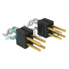
FTSH-108-01-LM-DH-C-TR
Samtec Inc.
CONN HEADER SMD R/A 16POS 1.27MM
ACS780LLSTR-100B-T
Allegro MicroSystems
SENSOR CUR HALL 100A 7POWERSMD
CS445AT
Infineon Technologies
IC SCREEN CNTRL TRUETOUCH
CY62157DV30L-70BVXI
Cypress Semiconductor Corp
IC SRAM 8MBIT PARALLEL 48VFBGA
MAX7033EUI+
Analog Devices Inc./Maxim Integrated
RF RX ASK 315MHZ/433MHZ 28TSSOP
HIP5010IS
Harris Corporation
HIP5010 - 7V, 17 AMP SYNCHROFET
PS2706-1-F3-A
CEL
OPTOISOLATOR 3.75KV DARL 4SMD
RT9078-25GJ5
Richtek USA Inc.
IC REG LIN 2.5V 300MA TSOT23-5 -
SM5S24A
Rectron USA
TVS DIODE 28.1VWM 38.9VC DO218
DZ23C6V8-7
Diodes Incorporated
DIODE ZENER ARRAY 6.8V SOT23-3
08052U1R5BAT2A
KYOCERA AVX
CAP CER 1.5PF 200V NP0 0805
ISL85410FRZ-T
Renesas Electronics America Inc
IC REG BUCK ADJUSTABLE 1A 12DFN
LE88266DLC
Microchip Technology
IC TELECOM INTERFACE 80LQFP
XC5VSX50T-2FFG665C
AMD
IC FPGA 360 I/O 665FCBGA
MC78LC28NTRG
onsemi
IC REG LINEAR 2.8V 80MA 5TSOP
LTC4364IS-2#TRPBF
Analog Devices Inc.
SURGE STOPPER W/DIODE SMD
XC6221B102MR-G
Torex Semiconductor Ltd
IC REG LINEAR 1V 200MA SOT25
74AHC1GU04W5-7
Diodes Incorporated
IC INVERTER 1CH 1-INP SOT25
PM8903
STMicroelectronics
IC REG BUCK ADJ 3A 16VFQFPN
NR4012T221M
Taiyo Yuden
FIXED IND 220UH SMD
DTA123ECAT116
Rohm Semiconductor
PNP -100MA -50V DIGITAL TRANSIST
MC34167THG
onsemi
IC REG BUCK BST ADJ 5.5A TO220-5
LMK107SD153KA-T
Taiyo Yuden
CAP CER 0.015UF 10V 0603
LX2208ILD-TR
Microsemi Corporation
IC BATT CHG LI-ION 1CELL 12MLPD
CLC4601ISO14X
MaxLinear, Inc.
IC OPAMP CFA 4 CIRCUIT 14SOIC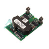
2SC0106T2A1-12
Power Integrations
IC GATE DRVR HALF-BRIDGE MODULE