EPM7064STC100-7 CPLD: Features, Applications, and In-System Programming Guide
The EPM7064STC100-7 is a powerful chip from Intel's MAX® 7000S series, designed to handle complex tasks in electronic devices. This guide discusses the main features and uses of the EPM7064STC100-7, emphasizing its ability to be reprogrammed easily, its quick operation, and its flexible design. Ideal for many different technologies, from small gadgets to big industrial machines, this chip is a key piece for building advanced digital circuits.Catalog
EPM7064STC100-7 Description
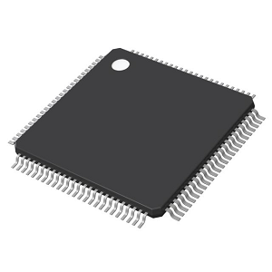
The EPM7064STC100-7 is a Complex Programmable Logic Device (CPLD) from Intel's MAX® 7000S series. It has 64 macrocells and 1,250 gates, which help in building complex digital circuits. This chip runs at a maximum speed of 166.7 MHz, with a signal delay of 7.5 nanoseconds (ns). It has 68 input/output (I/O) pins that work with 3.3V and 5V logic, making it easy to use in different circuits. A key feature is its 5.0V in-system programmability (ISP) through a JTAG interface (IEEE 1149.1). This means you can reprogram it without removing it from the circuit, making testing and updates easier. It comes in a 100-pin Thin Quad Flat Pack (TQFP), which is a compact, surface-mount package. This CPLD is used in embedded systems, digital signal processing, communication devices, and industrial automation.
We provide high-quality components and customized services, so it's best to place your bulk order with us for reliable CPLD solutions.
EPM7064STC100-7 Features
• High-Density Logic: The EPM7064STC100-7 is designed with 64 macrocells and 1,250 usable gates, making it highly suitable for implementing complex logic functions in digital circuits. This high-density architecture enables to create intricate logic designs while maintaining efficiency in programmable logic operations. The well-optimized macrocell structure ensures effective utilization of available resources, supporting advanced combinational and sequential logic implementations.
• Fast Performance: Built for high-speed processing, the EPM7064STC100-7 operates with a maximum internal frequency of 166.7 MHz, allowing for swift execution of logic functions. Its propagation delay of 7.5 ns ensures minimal latency. This rapid switching capability enhances the device’s ability to handle high-speed data processing, signal conditioning, and control tasks efficiently, making it a reliable choice for demanding digital systems.
• Versatile I/O: With 68 programmable input/output pins, the EPM7064STC100-7 offers exceptional flexibility for integration into various circuit designs. Supporting both 3.3V and 5V logic levels, it allows seamless compatibility with different system voltages, eliminating the need for additional voltage level shifters. This adaptability makes it well-suited for applications in mixed-voltage environments, ensuring broad applicability across embedded systems, industrial controls, and communication networks.
• In-System Programmability (ISP): One of the advantages of the EPM7064STC100-7 is its 5.0V in-system programmability (ISP), facilitated through an IEEE Std. 1149.1 JTAG interface. This feature allows to reprogram and modify logic functions without desoldering or physically removing the device, simplifying maintenance, debugging, and iterative development. The ISP capability reduces downtime and enhances the flexibility of firmware updates, making it invaluable for dynamic and reconfigurable digital designs.
EPM7064STC100-7 CAD Models
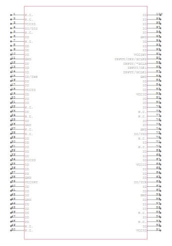
EPM7064STC100-7 Symbol
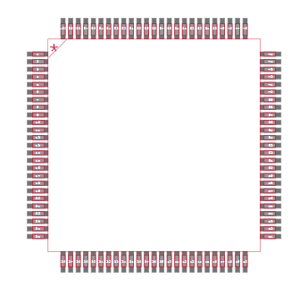
EPM7064STC100-7 Footprint
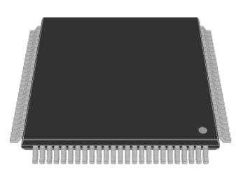
EPM7064STC100-7 3D Model
EPM7064STC100-7 Block Diagram
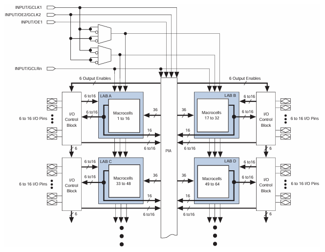
The EPM7064STC100-7 block diagram shows how the chip's logic elements are connected and controlled. It has four Logic Array Blocks (LABs), labeled A, B, C, and D, each containing 16 macrocells. These macrocells perform logic functions, and they connect through a Programmable Interconnect Array (PIA), which allows flexible routing of signals. Each LAB is linked to an I/O Control Block, handling up to 16 input/output pins per LAB. The diagram also shows global control signals (GCLK1, GCLK2, OE1, and GCLRn) that help manage clocking and reset functions for the chip. Some logic gates process these signals before they reach different parts of the system. The design of the EPM7064STC100-7 allows it to be used in various programmable logic applications, such as state machines, address decoding, and other custom digital circuits. Its flexible interconnections ensure efficient signal flow and reliable operation.
EPM7064STC100-7 Specifications
|
Type |
Parameter |
|
Manufacturer |
Altera/Intel |
|
Series |
MAX® 7000S |
|
Packaging |
Tray |
|
Part Status |
Obsolete |
|
Programmable Type |
In System Programmable |
|
Delay Time tpd(1) Max |
7.5 ns |
|
Voltage Supply - Internal |
4.75V ~ 5.25V |
|
Number of Logic Elements/Blocks |
4 |
|
Number of Macrocells |
64 |
|
Number of Gates |
1250 |
|
Number of I/O |
68 |
|
Operating Temperature |
0°C ~ 70°C (TA) |
|
Mounting Type |
Surface Mount |
|
Package / Case |
100-TQFP |
|
Supplier Device Package |
100-TQFP (14x14) |
|
Base Product Number |
EPM7064 |
EPM7064STC100-7 In-System Programming (ISP) Sequence
The EPM7064STC100-7, a part of the MAX 7000S CPLD family, follows a six-stage In-System Programming (ISP) sequence to ensure correct configuration. This process enables you to program the device without removing it from the circuit board. The ISP process involves shifting instructions, addresses, and data through the TDI (Test Data In) pin while retrieving responses via the TDO (Test Data Out) pin.
The first stage, Enter ISP, ensures that I/O pins transition smoothly from user mode to ISP mode and requires approximately 1ms. This is followed by Check ID, where the silicon ID of the device is read to confirm the correct target. Next, the Bulk Erase stage shifts in erase instructions and applies a 100ms erase pulse, clearing all existing data in the EEPROM cells. The Program stage follows, where addresses and data are sequentially shifted into the device, applying programming pulses to configure the EEPROM cells. Each address must be programmed individually, making this step time-consuming depending on the number of EEPROM cells in the device.
Once programming is complete, the Verify stage ensures that data has been stored correctly. Here, read pulses are applied to EEPROM cells, and the retrieved data is compared to the expected values. If discrepancies are found, reprogramming may be necessary. Finally, the Exit ISP stage ensures that I/O pins transition back to user mode, requiring another 1ms. The total programming or verification time is influenced by two main factors: pulse time, required for EEPROM erase, programming, and read operations, and shifting time, which depends on the TCK (Test Clock) frequency and the number of cycles needed to transfer instructions, addresses, and data. Since different ISP-capable devices have varying numbers of EEPROM cells, both total fixed and variable times are unique to each device. The total ISP time can be calculated as a function of TCK frequency, the number of target devices, and the EEPROM architecture.
EPM7064STC100-7 Applications
Embedded Systems
The EPM7064STC100-7 is widely used in embedded system applications, where it serves as a flexible programmable logic solution for controlling various peripherals, processing signals, and implementing custom protocols. Its ability to interface with microcontrollers and sensors allows to optimize system performance while maintaining a compact footprint. With its high-speed operation and low power consumption, it is an excellent choice for embedded applications that require reliability and efficiency.
Digital Signal Processing (DSP)
In digital signal processing, the EPM7064STC100-7 plays a role in implementing filters, signal modulation, and various mathematical functions. Its fast switching speeds and low propagation delay make it suitable for handling high-frequency data processing tasks, ensuring minimal latency in signal conversion and manipulation. It is commonly used in audio processing, telecommunications, and radar systems.
Data Communications
The EPM7064STC100-7 is extensively used in networking and data communication systems due to its ability to handle logic-intensive operations like data routing, buffering, and error correction. Its programmable I/O capabilities allow it to adapt to different communication protocols, making it a valuable component in Ethernet switches, routers, and telecommunication infrastructure. Its support for in-system programmability (ISP) also enables field updates, improving adaptability in dynamic networking environments.
Industrial Automation
Industrial applications demand high reliability, durability, and low power consumption, making the EPM7064STC100-7 a preferred choice for programmable logic controllers (PLCs), motor control systems, and automated testing equipment. With its JTAG-based in-system programmability, it provides the ability to refine automation processes without requiring physical removal or redesign. Its versatility in voltage compatibility also makes it suitable for interfacing with a wide range of sensors and actuators used in industrial settings.
EPM7064STC100-7 Similar Parts
EPM7064STC100-7 Advantages
In-System Programmability (ISP)
One of the biggest advantages of the EPM7064STC100-7 is its ability to be reprogrammed while still mounted in the system. This eliminates the need for removing the chip for updates, reducing maintenance time and improving efficiency. You can implement design modifications without interrupting production, making it a cost-effective solution for long-term projects.
High-Speed Performance
The device supports a high internal operating frequency of up to 166.7 MHz, allowing for fast data processing and response times. This makes it ideal for applications requiring signal processing, logic control, and high-speed interfacing, ensuring smoother and more reliable system operation.
Versatile I/O Support
With up to 68 configurable I/O pins and compatibility with multiple voltage levels (3.3V, 5V, and tolerant options for 2.5V, 3.3V, and 5V), the EPM7064STC100-7 offers flexibility in system design. It allows seamless integration into various circuits and supports mixed-voltage environments, reducing compatibility issues with other components.
Reliable Operation Across Environments
Designed to function within a temperature range of 0°C to 70°C, the EPM7064STC100-7 ensures consistent and stable operation in a variety of conditions. This reliability makes it a preferred choice for applications where environmental stability is required, such as industrial automation, telecommunications, and embedded control systems.
EPM7064STC100-7 Package Pin-Out Diagram
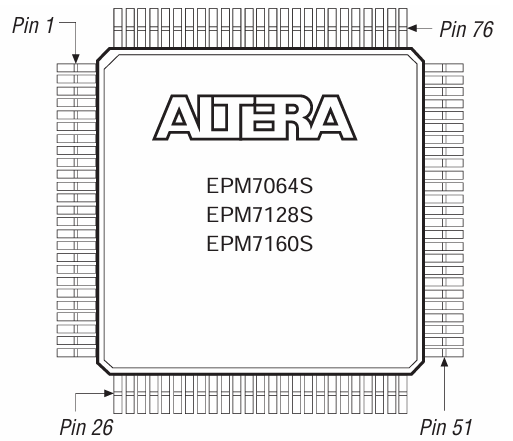
The EPM7064STC100-7 is a CPLD (Complex Programmable Logic Device) from Altera’s MAX 7000S series, housed in a 100-pin Thin Quad Flat Package (TQFP-100). This package type is designed for surface-mount applications, offering a balance of high pin density and compact size. The pin-out diagram follows a counterclockwise numbering scheme, with Pin 1 located at the top-left corner of the package. Moving counterclockwise, the first 25 pins occupy the left side, pins 26 to 50 are positioned along the bottom edge, pins 51 to 75 continue along the right side, and pins 76 to 100 are distributed along the top edge. The TQFP-100 package features thin leads extending outward from all four sides of the flat, square body. This design enhances surface-mount compatibility while maintaining adequate pin spacing for easy soldering and assembly. The lead pitch (distance between adjacent pins) is typically 0.5mm, optimizing signal integrity while minimizing the overall footprint.
EPM7064STC100-7 Manufacturer
The EPM7064STC100-7 is a CPLD (Complex Programmable Logic Device) originally developed by Altera, a semiconductor company known for its programmable logic solutions. In 2015, Intel acquired Altera, integrating its FPGA and CPLD product lines into Intel’s Programmable Solutions Group (PSG). Since then, the EPM7064STC100-7 has been branded under Intel, although it has been marked as obsolete. Intel, as the manufacturer, maintained the legacy support for MAX® 7000S series CPLDs, including this model, while gradually shifting its focus toward modern FPGA and programmable logic technologies.
Conclusion
The EPM7064STC100-7 brings together complex functions, fast performance, and easy updates in one chip, proving its value in challenging digital setups. This guide has shown how it works, what it’s used for, and how it fits into various electronic systems. It helps make devices run smoothly and efficiently, proving that it's still very useful for many applications. This guide provides a clear view of how the EPM7064STC100-7 can help improve electronic designs and system operations effectively.
Datasheet PDF
EPM7064STC100-7 Datasheets:
About us
ALLELCO LIMITED
Read more
Quick inquiry
Please send an inquiry, we will respond immediately.
Frequently Asked Questions [FAQ]
1. How does the 7.5ns propagation delay of the EPM7064STC100-7 impact circuit performance?
A 7.5ns propagation delay ensures low-latency signal processing, making this CPLD suitable for high-speed applications such as digital signal processing (DSP), communication systems, and industrial automation that require precise timing control.
2. Can the EPM7064STC100-7 be programmed using modern development tools?
Yes, it can be programmed using Intel's Quartus II software (formerly Altera Quartus) along with an appropriate JTAG programmer. However, support for older CPLDs like the EPM7064STC100-7 may be limited in newer Quartus versions, so you may need to use legacy versions like Quartus II 13.0 SP1, which still support MAX® 7000S series devices.
3. Does the EPM7064STC100-7 support mixed-voltage environments?
Yes, it supports both 3.3V and 5V logic levels, making it compatible with a wide range of digital circuits. This flexibility is useful for interfacing legacy 5V components with modern 3.3V systems without additional level-shifting circuitry.
4. What is the best method for troubleshooting an EPM7064STC100-7-based design?
To troubleshoot, you can use Quartus SignalTap II Logic Analyzer or external oscilloscopes and logic analyzers to monitor signals. If debugging JTAG programming issues, ensure that TDI, TDO, TCK, and TMS connections are correct and that you’re using a compatible USB Blaster or ByteBlasterMV programmer.
5. Can I program the EPM7064STC100-7 without removing it from my circuit board?
Yes. The 5.0V in-system programmability (ISP) via JTAG (IEEE 1149.1) allows you to reprogram the device while it remains in the system. This makes firmware updates, debugging, and testing much more efficient compared to traditional CPLDs.
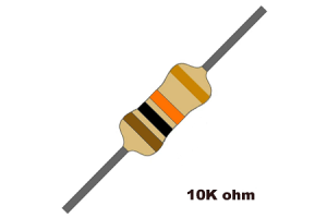
Complete Guide to the 10k Resistor: Color Code, Applications, and Circuit Uses
on March 10th
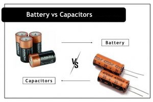
Capacitors vs. Batteries: Which is best for your energy needs?
on March 7th
Popular Posts
-

Complex Instruction Set Computers: How They Changed Computing?
on April 18th 147776
-

USB-C Pinout and Features
on April 18th 112018
-

Using Xilinx Unified Simulation Primitives: A Comprehensive Guide to FPGA Design and Simulation
on April 18th 111351
-

Power Supply Voltages in Electronics: Meaning of VCC, VDD, VEE, VSS, and GND
on April 18th 83775
-

RJ45 Connector Guide: Pinout, Wiring, Cable Types, and Uses
on January 1th 79571
-

The Ultimate Guide to Wire Color Codes in Modern Electrical Systems
The way our electrical systems use colors isn’t just for looks. Each wire color now indicates a specific function, making it easier to identify and handle electrical components correctly during ins...on January 1th 66962
-

Purge Valve Guide: Function, Symptoms, Testing, and Replacement for Optimal Engine Performance
The purge valve is a key part of a car’s system that helps keep the air clean by managing fuel vapors before they can escape into the atmosphere. This not only helps the environment by reducing pol...on January 1th 63104
-

Quality (Q) Factor: Equations and Applications
The quality factor, or 'Q', is important when checking how well inductors and resonators work in electronic systems that use radio frequencies (RF). 'Q' measures how well a circuit minimizes energy...on January 1th 63041
-

Achieving Peak Performance with the Maximum Power Transfer Theorem
The Maximum Power Transfer Theorem explains how energy from a source, such as a battery or generator, flows to a connected load. It shows the exact condition where the load receives the most power....on January 1th 54097
-

A23 Battery Specifications and Compatibility
The A23 battery is a small, cylinder-shaped battery with high voltage. Also called 23A, 23AE, or MN21, it runs at 12 volts and much higher than AA or AAA batteries. Its special design make...on January 1th 52186
HOT Part Number
-
CC0603KRX7RYBB102
YAGEO
CAP CER 1000PF 250V X7R 0603
DDZ9684Q-7
Diodes Incorporated
DIODE ZENER 3.3V 500MW SOD123
MAX4104EUK+T
Analog Devices Inc./Maxim Integrated
IC OPAMP VFB 1 CIRCUIT SOT23-5
GD25Q20CTIGR
GigaDevice Semiconductor (HK) Limited
IC FLASH 2MBIT SPI/QUAD I/O 8SOP
LP2986IMMX-5.0
Texas Instruments
IC REG LINEAR 5V 200MA 8MSOP PWR
BAS16TWQ-13R-F
Diodes Incorporated
DIODE FS 100V 150MA SOT363
L130-3080002011001
Lumileds
LED LUXEON WARM WHITE 3000K 2SMD
TOP268KG
Power Integrations
IC OFFLINE SWITCH FLYBACK 12ESOP
DAC8168ICPW
Texas Instruments
IC DAC 14BIT V-OUT 16TSSOP
DF3DZ-3P-2H(51)
Hirose Electric Co Ltd
CONN HEADER SMD R/A 3POS 2MM
LTV-817S-TA1-C
Lite-On Inc.
OPTOISOLATR 5KV TRANSISTOR 4-SMD
11AA080-I/SN
Microchip Technology
IC EEPROM 8KBIT SGL WIRE 8SOIC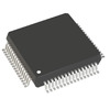
R5F562T7DDFK#V1
Renesas Electronics America Inc
IC MCU 32BIT 128KB FLASH 64LQFP
NBSG16VSMN
onsemi
IC TRANSCEIVER 16QFN
VI-J43-EX
Vicor Corporation
DC DC CONVERTER 24V 75W
MI-AIM-I1
Vicor Corporation
MI-AIM-I1
TLF80511TCATMA1
Infineon Technologies
IC REG LINEAR 5V 400MA TO263-3
RT1206BRE07220KL
YAGEO
RES SMD 220K OHM 0.1% 1/4W 1206 -
GRM2196R2A9R2DD01D
Murata Electronics
CAP CER 9.2PF 100V R2H 0805
NCP7812BTG
onsemi
IC REG LINEAR 12V 1A TO220AB
RB521VM-40FHTE-17
Rohm Semiconductor
DIODE SCHOTTKY 40V 200MA UMD2
KSB834YTU
onsemi
TRANS PNP 60V 3A TO220-3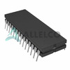
AD7506SQ
Analog Devices Inc.
IC MUX 16:1 450OHM 28CDIP
EP4CE15F17C6N
Intel
IC FPGA 165 I/O 256FBGA
GD25S512MDFIGR
GigaDevice Semiconductor (HK) Limited
IC FLASH 512MBIT SPI/QUAD 16SOP
AON7422GS
Alpha & Omega Semiconductor Inc.
MOSFET N-CH 8SOIC
UDZVFHTE-1713B
Rohm Semiconductor
DIODE ZENER 13V 200MW UMD2
SIR462DP-T1-GE3
Vishay Siliconix
MOSFET N-CH 30V 30A PPAK SO-8
TSC2003IPW
Texas Instruments
IC SCREEN CNTRL 12BIT 16TSSOP
75K62134S167BBG
Broadcom Limited
9MB QDR IIPC
C3225JB2A155M200AB
TDK Corporation
CAP CER 1.5UF 100V JB 1210
LTC6655BHMS8-1.25#TRPBF
Analog Devices Inc.
IC VREF SERIES 0.025% 8MSOP
USB5806T/KD
Microchip Technology
IC HUB CONTROLLER USB 100VQFN
TUSB3200ACPAHR
Texas Instruments
IC USB STREAMING CNTRLR 52-TQFP
NTS0101GF,132
NXP USA Inc.
IC TRANSLTR BIDIRECTIONAL 6XSON
V375B3V3C150BN4
Vicor Corporation
C 250/425/375 3.3V/ 45.5A -
P6KE62C
Diotec Semiconductor
TVS DO-15 50.2V 600W BI
STM32F303RET6
STMicroelectronics
IC MCU 32BIT 512KB FLASH 64LQFP
LQP02HQ20NH02E
Murata Electronics
FIXED IND 20NH 140MA 2.26OHM SMD
OPA2704EA/250
Texas Instruments
IC CMOS 2 CIRCUIT 8VSSOP
MAX3081EPA
Analog Devices Inc./Maxim Integrated
RS-485/RS-422 TRANSCVR
CL10B332JB8NNNC
Samsung Electro-Mechanics
CAP CER 3300PF 50V X7R 0603
TL2575-05IN
Texas Instruments
IC REG BUCK 5V 1A 16DIP
MAX749EPA+
Analog Devices Inc./Maxim Integrated
IC SUPPLY LCD BIAS ADJ 8-DIP
AONS21321
Alpha & Omega Semiconductor Inc.
MOSFET P-CH 30V 14A/24A 8DFN
MAX3160EEAP+
Analog Devices Inc./Maxim Integrated
IC TRANSCEIVER FULL 2/2 20SSOP
BLF178P,112
Ampleon USA Inc.
RF FET LDMOS 110V 28.5DB SOT539A
MAX2606EUT
Analog Devices Inc./Maxim Integrated
IF VCO WITH DIFFERENTIAL OUTPUT
AXA005A0XZ
ABB Power Electronics Inc.
DC DC CONVERTER 0.8-5.5V 27W
STL11N6F7
STMicroelectronics
MOSFET N-CH 60V 11A POWERFLAT
MK5811SLF
Renesas Electronics America Inc
IC CLOCK GENERATOR 8SOIC
1N4752A
NTE Electronics, Inc
DIODE ZENER 33V 1W AXIAL
CY74FCT16652ATPVC
Texas Instruments
IC TXRX NON-INVERT 5.5V 56SSOP
CIH03Q3N9CNC
Samsung Electro-Mechanics
FIXED IND 3.9NH 270MA 300MOHM SM