Exploring the IC 741 Op-Amp: Features, Pinout, and Applications
This guide explores the IC 741 operational amplifier, a core of analog circuit design since its introduction by Fairchild Semiconductors in 1963. Celebrated for its flexibility, the IC 741 op-amp has become a staple in countless electronic projects due to its compact form and reliable performance. From simple signal amplification to complex mathematical functions, this guide examines the role and contributions of the IC 741 op-amp in advancing electronic applications and improving circuit design.Catalog
What is the IC 741 Operational Amplifier?
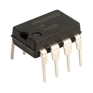
Renowned for its adaptability and compact design, the IC 741 operational amplifier plays a role in a myriad of electronic applications. Typically encased in an 8-pin configuration, the IC centers its operations around specific pins, notably pins 2 (inverting input), 3 (non-inverting input), and 6 (output voltage). The op-amp's design is represented by a triangle, a symbol of the three main stages that form the core of its architecture: the differential input stage, an intermediate gain stage, and a push-pull output stage. In the 741 series op-amp, the differential input stage incorporates intricately matched pairs of FETs or bipolar transistors. This meticulous matching reduces offset voltage while providing high input resistance, bolstering the reliability of signal amplification. Such technical pairing is needed for achieving a low noise floor, a quality that enhances performance in delicate audio and signal processing tasks.
IC 741 Op-Amp Pin Configuration

|
Pin No. |
Pin Name |
Description |
|
1 |
Offset Null |
Used for adjusting the offset voltage. |
|
2 |
Inverting Input (-) |
Input terminal where the signal is inverted. |
|
3 |
Non-Inverting Input (+) |
Input terminal where the signal is not inverted. |
|
4 |
Negative Voltage Supply (V-) |
Provides negative voltage supply (VCC). |
|
5 |
Offset Null |
Used for adjusting the offset voltage. |
|
6 |
Output |
Output terminal for the voltage. |
|
7 |
Positive Voltage Supply (+VCC) |
Provides positive voltage supply. |
|
8 |
Not Connected (NC) |
This pin has no connection. |
IC 741 Op-Amp Amplification

Inverting Amplifier
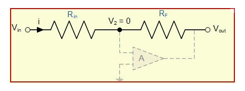
The inverting amplifier setup is intriguing due to its arrangement, where pin 2 receives the input, and pin 6 outputs the signal, albeit in reversed phase. A positive input voltage naturally leads to a negative output, a fascinating interplay of electrical principles. The gain, expressed as
![]()
holds a particular allure for those needing control and precision. Picture this: Rf set to 1000 kΩ and R1 at 100 kΩ, delivering a gain of -10. An initial 1.5V input morphs into a -15V output, an accomplishment in phase shift and amplification control. This configuration finds favor in scenarios like audio processing and sensor signal tuning, where careful transformation of signals is an important part of the process.
Non-Inverting Amplifier
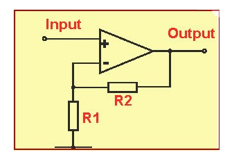
This configuration paints a contrasting portrait: immaculate amplification without altering phase. Here, the input graces pin 3, while pin 6 faithfully mirrors it in strength. The gain, given by
![]()
let you confidently predict outcomes, for example, with Rf at 50 kΩ and R1 at 10 kΩ, yielding a gain of 6. A humble 1V input manifests as a robust 6V output. Often called upon in roles as varied as buffer amplifiers within instrumentation, this design provides unwavering stability and clarity. It shines in sensitive like high-precision biomedical devices and intricate communication systems, where preserving the essence of a signal with integrity and dependability is a pathway to success.
Circuit Diagram of IC 741 Op-Amp
The IC 741 operational amplifier plays a role in a myriad of practical circuits, extending its talents to areas like signal conditioning and arithmetic operations. It enhances precise analog circuits, contributing to the handling of diverse signals with a finesse that is appreciated seeking performance and reliability.

IC 741 Op-Amp Circuit Diagram
IC 741 Op-Amp Specifications
|
Type |
Parameter |
|
Input Offset Voltage |
Typically ±2 mV, maximum ±6 mV |
|
Input Offset Current |
Typically ±20 nA, maximum ±200 nA |
|
Input Bias Current |
Typically ±80 nA, maximum ±500 nA |
|
Differential Input Resistance |
2 MΩ to 10 MΩ |
|
Input Capacitance |
1.4 pF |
|
Offset Voltage Adjustment Range |
±10 mV using external potentiometer |
|
Input Voltage Range |
±13 V with ±15 V supply |
|
CMRR (Common Mode Rejection Ratio) |
Typically 90 dB, minimum 70 dB |
|
SVRR (Supply Voltage Rejection Ratio) |
Typically 96 dB, minimum 70 dB |
|
Power Consumption |
Typically 85 mW at ±15 V supply |
|
Transient Response |
0.3 μs for 5 V step change in output |
|
Slew Rate (SR) |
0.5 V/μs |
IC 741 Op-Amp Features
High Input Impedance
Over 100 kΩ, reducing the risk of loading effects on signal sources.
Ensures smooth integration with a wide variety of circuits without signal loss.
Low Output Impedance
Typically under 100 Ω, enabling efficient power delivery to connected loads.
Prevents signal reflection issues and maintains circuit stability under varying load conditions.
Wide Frequency Range
Operates from 0 Hz to 1 MHz, making it suitable for DC, audio, and moderate RF applications. Reliable for both low- and high-frequency signal processing.
Low Offset Voltage
Minimizes output errors due to input offset, enhancing accuracy in precision applications. Reduces the need for additional calibration or correction circuits.
High Voltage Gain
Gain of up to 200,000 allows amplification of weak signals, ideal for sensors and transducers. Supports applications requiring high signal integrity.
Versatile and Reliable
Dependable performance across educational, consumer, and industrial electronics projects. Simple yet robust design makes it a staple in analog circuit design.
Applications of IC 741 Op-Amp
Versatile Building Blocks for Circuit Design
IC 741 op-amps are excellent in countless electronic applications due to their flexibility and reliability. They are commonly used to design active filters, current-to-voltage converters, analog-to-digital converters, voltage followers, and summing amplifiers. They play a role in sample-and-hold circuits, variable frequency oscillators, and ripple-regulated power supplies, making them use in audio processing and precision devices.
Audio Processing and Environmental Monitoring
The IC 741 op-amp is used in audio mixers, ensuring signal clarity in mixing consoles. It also supports environmental systems, such as automatic light switches and DC voltage indicators. Others rely on its stability and precision for tasks requiring signal accuracy, such as in room thermometers and sound-sensitive bug listening devices.
Communication and Signal Processing
For applications like microphone amplifiers, the IC 741 minimizes distortion and manages noise, delivering clear audio quality. It also powers voltage-to-frequency converters in frequency modulation and signal processing.
About us
ALLELCO LIMITED
Read more
Quick inquiry
Please send an inquiry, we will respond immediately.
Understanding the TIP127 Darlington Transistor: Pinout, Specifications, Circuit Design, and Applications
on December 10th

All You Need to Know About the CD4093 CMOS IC
on December 10th
Popular Posts
-

Complex Instruction Set Computers: How They Changed Computing?
on April 18th 147749
-

USB-C Pinout and Features
on April 18th 111904
-

Using Xilinx Unified Simulation Primitives: A Comprehensive Guide to FPGA Design and Simulation
on April 18th 111349
-

Power Supply Voltages in Electronics: Meaning of VCC, VDD, VEE, VSS, and GND
on April 18th 83714
-

RJ45 Connector Guide: Pinout, Wiring, Cable Types, and Uses
on January 1th 79502
-

The Ultimate Guide to Wire Color Codes in Modern Electrical Systems
The way our electrical systems use colors isn’t just for looks. Each wire color now indicates a specific function, making it easier to identify and handle electrical components correctly during ins...on January 1th 66869
-

Quality (Q) Factor: Equations and Applications
The quality factor, or 'Q', is important when checking how well inductors and resonators work in electronic systems that use radio frequencies (RF). 'Q' measures how well a circuit minimizes energy...on January 1th 63004
-

Purge Valve Guide: Function, Symptoms, Testing, and Replacement for Optimal Engine Performance
The purge valve is a key part of a car’s system that helps keep the air clean by managing fuel vapors before they can escape into the atmosphere. This not only helps the environment by reducing pol...on January 1th 62942
-

Achieving Peak Performance with the Maximum Power Transfer Theorem
The Maximum Power Transfer Theorem explains how energy from a source, such as a battery or generator, flows to a connected load. It shows the exact condition where the load receives the most power....on January 1th 54076
-

A23 Battery Specifications and Compatibility
The A23 battery is a small, cylinder-shaped battery with high voltage. Also called 23A, 23AE, or MN21, it runs at 12 volts and much higher than AA or AAA batteries. Its special design make...on January 1th 52087
HOT Part Number
-
LTC4063EDD#TRPBF
Analog Devices Inc.
IC BATT CHG LI-ION 1CELL 10DFN
MIMX8MM1CVTKZAA
NXP USA Inc.
IC MPU I.MX 8M MINI SOLOLITE
APDS-9005-020
Broadcom Limited
SENSOR OPT 500NM AMB 6CHIPLED
06031A820KAT2A
KYOCERA AVX
CAP CER 82PF 100V C0G/NP0 0603
ICM-20602
TDK InvenSense
IMU ACCEL/GYRO/TEMP I2C/SPI LGA
170M4611
Eaton - Bussmann Electrical Division
FUSE SQUARE 350A 700VAC RECT
08053C105JAZ2A
KYOCERA AVX
CAP CER 1UF 25V X7R 0805
EP1C12F324C6N
Intel
IC FPGA 249 I/O 324FBGA
2SC4617T1G
onsemi
TRANS NPN 50V 0.1A SC75 SOT416
TL431AILPRAG
onsemi
IC VREF SHUNT ADJ 1% TO92-3
ADAU1787BCBZRL
Analog Devices Inc.
4 ADC, 2 DAC LOW POWER CODEC, AU
74VHC164MTCX
onsemi
IC SHIFT REGISTER 8BIT 14TSSOP
DAN222M3T5G
onsemi
DIODE ARRAY GP 80V 100MA SOT723
NR3015T470M
Taiyo Yuden
FIXED IND 47UH 300MA 1.608OHM SM
MM3Z18VC
onsemi
DIODE ZENER 18V 200MW SOD323F
1N4001W
Rectron USA
DIODE GEN 1A 50V SOD-123F
SMBJ90A
Taiwan Semiconductor Corporation
TVS DIODE 90VWM 146VC DO214AA
NTA1215MC
Murata Power Solutions Inc.
DC DC CONVERTER +/-15V 1W -
SDR1307-101KL
Bourns Inc.
FIXED IND 100UH 1.9A 180MOHM SMD
AOT5B65M1
Alpha & Omega Semiconductor Inc.
IGBT 650V 5A TO220
STP16CP596B1R
STMicroelectronics
IC LED DRIVER LINEAR 50MA 24DIP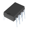
AD7895ANZ-2
Analog Devices Inc.
IC ADC 12BIT SAR 8DIP
MURB1620CTT4G
onsemi
DIODE ARRAY GP 200V 8A D2PAK
STGIPS30C60T-H
STMicroelectronics
MOD IPM SLLIMM 30A 600V 25SDIP
IXDN604SIA
IXYS Integrated Circuits Division
IC GATE DRVR LOW-SIDE 8SOIC
CY7C63743-SC
Infineon Technologies
IC MCU 8K LS USB/PS-2 24-SOIC
U2745B-MFBG3
Microchip Technology
RF TX IC UHF 310-440MHZ 16LSSOP
DSPIC30F4013T-30I/PT
Microchip Technology
IC MCU 16BIT 48KB FLASH 44TQFP
ADF4106BRUZ-RL
Analog Devices Inc.
IC CLK/FREQ SYNTH 16TSSOP
EL8403IS
Elantec
IC OPAMP GP 4 CIRCUIT 14SOIC
8A35001B-001AJG
Renesas Electronics America Inc
NETWORK TIMING
GRM0337U1HR90BD01D
Murata Electronics
CAP CER 0.9PF 50V U2J 0201
LT1356CS#PBF
Analog Devices Inc.
IC VOLTAGE FEEDBACK 2 CIRC 16SO
AON7280
Alpha & Omega Semiconductor Inc.
MOSFET N-CH 80V 20A/50A 8DFN
IRLI540N
Infineon Technologies
MOSFET N-CH 100V 23A TO220AB FP
VI-J6Z-MZ
Vicor Corporation
VI-J6Z-MZ 300V 2V 5A -
LMH6722MA
Texas Instruments
IC AMP CURRENT FEEDBACK 14SOIC
HZM6.8Z4MWATL-E
Renesas Electronics America Inc
TVS DIODE 3.5VWM 3MPAK
LM4041DIM7-1.2
Texas Instruments
IC VREF SHUNT 1% SC70-5
RT6200GE
Richtek USA Inc.
IC REG BUCK ADJ 600MA SOT23-6
R5F21274SNFP#X6
Renesas Electronics America Inc
IC MCU 16BIT 16KB FLASH 32LQFP
1N5227B
onsemi
DIODE ZENER 3.6V 500MW DO35
12102C472JAT2A
KYOCERA AVX
CAP CER 4700PF 200V X7R 1210
PZTA64
Fairchild Semiconductor
SMALL SIGNAL BIPOLAR TRANSISTOR,
XC1765ELSO8C
AMD
IC PROM SER C-TEMP 3.3V 8-SOIC
XR88C92CJ-F
MaxLinear, Inc.
IC UART FIFO DUAL 44PLCC
RT24C2X202
Bourns, Inc.
TRIMMER 2K OHM 0.75W PC PIN SIDE
DLW31SN900SQ2L
Murata Electronics
CMC 370MA 2LN 90 OHM SMD
LMK432F476ZM-T
Taiyo Yuden
CAP CER 47UF 10V Y5V 1812
MOC207R1VM
onsemi
OPTOISO 2.5KV TRANS W/BASE 8SOIC
GRM0335C1E390JD01D
Murata Electronics
CAP CER 39PF 25V C0G/NP0 0201
SE10PG-M3/84A
Vishay General Semiconductor - Diodes Division
DIODE GEN PURP 400V 1A DO220AA
RABS15M REG
Taiwan Semiconductor Corporation
BRIDGE RECT 1P 1KV 1.5A ABS-L
PI74LPT16245AEX
Diodes Incorporated
IC TXRX NON-INVERT 3.6V 48TSSOP