Full Bridge Rectifier: Efficient AC to DC Conversion, Circuit Design, and Applications
A Full Bridge Rectifier used to change alternating current (AC), like the power from your wall outlet, into direct current (DC), which is the type of power used by most electronic devices. Unlike simpler systems that waste half of the incoming electricity, the full bridge rectifier uses four diodes to make sure it captures power from both the up and down swings of the AC cycle. This article will explore how a full bridge rectifier works, its parts, and why it’s so important in many technologies today.Catalog

Overview of a Full Bridge Rectifier
A Full Bridge Rectifier, also known as a Full Wave Bridge Rectifier or simply a Diode Bridge Rectifier, is an electronic circuit designed to convert alternating current (AC) into direct current (DC). It serves as a component in many electrical and electronic applications where a steady DC voltage is required. Unlike a half-wave rectifier, which only utilizes one half of the AC waveform, a full bridge rectifier takes advantage of both the positive and negative halves of the AC cycle, making it more efficient in power conversion. The operation of a full bridge rectifier relies on a configuration of four diodes arranged in a bridge formation. These diodes work collectively to ensure that the direction of current flow remains the same across the load, regardless of the polarity of the AC input. This arrangement effectively allows the circuit to rectify both halves of the input waveform, resulting in a more continuous and stable DC output compared to a half-wave rectifier.
One of the key advantages of a full bridge rectifier is its enhanced efficiency. Since it processes the entire AC waveform rather than just one half, it generates a higher average DC output voltage, which is beneficial in practical applications. Additionally, by making full use of the input power, it reduces power loss and heat dissipation, making it a preferred choice in various power supply systems. Full bridge rectifiers are extensively used in regulated power supply circuits, including those found in power adapters, battery chargers, and computer power supplies. These devices demand a consistent and reliable DC voltage to ensure stable operation of electronic components. The ability of a full bridge rectifier to deliver smooth and efficient DC power makes it an important component in modern electrical and electronic engineering.

Figure 2. Full Bridge Rectifier Diagram
The circuit diagram illustrates the working principle of a Full Wave Bridge Rectifier, a common electronic component used to convert alternating current (AC) into direct current (DC). The circuit consists of four diodes (D1, D2, D3, and D4) arranged in a bridge configuration. It has two AC input terminals (labeled AC_P and AC_N) and two DC output terminals. When AC voltage is applied, the rectifier uses the diodes to ensure that the current flows in the same direction during both the positive and negative halves of the AC cycle. In the positive half-cycle, diodes D1 and D2 are forward-biased and allow current to pass, while D3 and D4 are reverse-biased and block current. During the negative half-cycle, D3 and D4 become forward-biased and conduct, while D1 and D2 block current. This process rectifies the AC input, producing a pulsating DC output. The capacitor (C0) smooths the output, reducing voltage fluctuations and creating a more stable DC voltage (Vout).
Construction of a Full Wave Bridge Rectifier

Figure 3. Full Wave Bridge Rectifier Construction
A Full Wave Bridge Rectifier, electronic circuit designed to convert alternating current (AC) into direct current (DC) efficiently. This rectification process relies on the combined operation of diodes and a resistive load, each contributing to the circuit's functionality and efficiency. The rectifier's construction consists of the following main components:
1. Four Diodes (D₁, D₂, D₃, D₄)
The four diodes are the heart of the circuit and are arranged in a bridge configuration. They play a role in the rectification process by allowing current to flow in only one direction through the load, regardless of the AC input polarity. Each diode acts as a one-way valve for electric current. During the positive half-cycle of the AC input, diodes D₁ and D₂ become forward-biased, allowing current to flow through the load. At the same time, diodes D₃ and D₄ are reverse-biased and block the current. This ensures that current flows in a single direction through the load.
During the negative half-cycle of the AC input, the roles of the diodes reverse. Diodes D₃ and D₄ become forward-biased, conducting current, while diodes D₁ and D₂ are reverse-biased and block current. Again, the current flows in the same direction through the load, maintaining a unidirectional current. This alternating operation of the diodes ensures that both halves of the AC waveform are utilized, resulting in a more efficient conversion compared to a half-wave rectifier, which only uses one half of the AC cycle.
2. Resistive Load (RL)
The resistive load, labeled RL in the diagram, represents the component or device that utilizes the rectified DC output. This load could be a resistor, an electronic device, or any appliance that requires DC power to function. The rectified current flows through the load, delivering usable power. The circuit's performance and efficiency largely depend on the characteristics of the load and the quality of the rectified output. The load is connected across the DC output terminals, labeled B and D in the diagram. The direction of the current flow through the load remains consistent due to the rectification process, ensuring the delivery of a unidirectional DC current.
3. AC Input Terminals (A and C)
The rectifier has two input terminals labeled A and C, where the AC supply is connected. The polarity of the AC input alternates periodically, with the positive and negative half-cycles being processed differently by the diodes. The input voltage is channeled through the bridge network, ensuring that both halves of the AC waveform contribute to the output current.
4. DC Output Terminals (B and D)
The rectifier produces a DC voltage across the output terminals, labeled B and D in the diagram. The output is a pulsating DC waveform, with the negative half of the AC cycle inverted to align with the positive half. Although this waveform is unidirectional, it still contains some fluctuations, or ripples, due to the rectification process. The Full Wave Bridge Rectifier is highly efficient because it utilizes both halves of the AC waveform, effectively doubling the frequency of the output signal compared to a half-wave rectifier. This increased frequency makes it easier to smooth out the ripples using filtering components like capacitors or inductors, producing a more stable DC output for practical applications. This design is widely used in power supply circuits due to its ability to provide a higher average output voltage, improved efficiency, and better utilization of the input power compared to simpler rectifier circuits.
Functionality of a Full Bridge Rectifier
The Full Bridge Rectifier, renowned for its ability to convert alternating current (AC) into direct current (DC). AC, commonly available in residential, commercial, and industrial electrical systems, is unsuitable for most electronic devices due to its bidirectional nature, which alternates between positive and negative cycles. The Full Bridge Rectifier addresses this issue by using a strategic configuration of diodes to facilitate the transformation of AC into DC, enabling electronic devices to operate reliably. The rectification process begins as the AC input, which naturally follows a sinusoidal pattern with alternating positive and negative half-cycles, enters the rectifier circuit. The rectifier’s design consists of four diodes, arranged in a bridge configuration, that work together to channel the flow of electricity in one direction only. As the AC input alternates, specific pairs of diodes conduct during each half-cycle.
To create a more stable and usable DC voltage, the rectifier's output is usually passed through a filtering component, such as a capacitor. The capacitor plays a role by storing charge during the peaks of the pulsating DC and releasing it during the troughs, effectively reducing fluctuations and smoothing the waveform. The resulting DC voltage is much more consistent and suitable for powering electronic devices. The importance of the Full Bridge Rectifier extends far beyond simple conversion. Its steady DC output is great for the proper functioning of a wide range of electronic devices, from small household gadgets like smartphones, tablets, and laptops to larger, more complex systems like computer servers, telecommunication networks, and industrial machinery. These devices and systems require a stable and continuous power supply to avoid performance issues or potential damage caused by fluctuations in the electrical input. The rectifier’s ability to utilize both halves of the AC waveform makes it more efficient than a half-wave rectifier, providing a higher average output voltage and minimizing energy wastage. By ensuring a constant and reliable DC supply, the Full Bridge Rectifier not only enhances the performance of the devices it powers but also extends their lifespan by protecting sensitive components from voltage irregularities. This efficiency and reliability make it an element in modern power electronics and energy conversion systems.
Operational Dynamics of a Full Bridge Rectifier
The operation of a Full Bridge Rectifier is both intricate and needed for converting alternating current (AC) into direct current (DC), a transformation important for powering countless electronic devices. This process can be understood as a series of interconnected phases, each playing a role in ensuring the efficiency, stability, and reliability of the DC output.
1. AC Input and Transformer Adjustment
The rectification process begins with an AC input, typically sourced from a standard power supply, such as a wall outlet. However, the voltage of this AC input is often too high or unsuitable for direct use in electronic circuits. To address this, a transformer is employed to step down the voltage to a safer and more manageable level. The transformer not only adjusts the input voltage but also isolates the circuit from the main power supply, providing an additional layer of safety. By stepping down the voltage, the transformer ensures that the rectifier operates efficiently while minimizing the risk of voltage spikes or surges that could damage delicate electronic components. This preparation stage is important for making the input AC ready for the subsequent rectification process.
2. Diode Activation During Positive and Negative Half-Cycles


3. Capacitor Filtering
The rectified output at this stage, while unidirectional, still contains fluctuations or ripples due to the alternating nature of the original AC input. To smooth out these ripples and produce a more stable DC voltage, a capacitor is placed across the output of the rectifier. The capacitor works by charging when the rectified voltage reaches its peak and discharging when the voltage drops. This process fills in the gaps between the pulses of the rectified waveform, effectively reducing voltage variations. The result is a much smoother DC output for powering sensitive electronic devices. In applications requiring precision, such as medical equipment, communication devices, and microcontrollers, this filtering stage ensures that the voltage supplied remains steady and reliable.
4. Voltage Stabilization
Even after filtering, minor fluctuations or irregularities may persist in the DC output. To further refine the quality of the voltage, additional voltage stabilization components, such as voltage regulators or more advanced filtering circuits, are often employed. Voltage regulators are designed to maintain a constant output voltage, even if the input voltage or load conditions vary. This stabilization is important for devices that require an exact and consistent voltage supply, such as processors, sensors, or memory modules. By ensuring that the output voltage remains within a precise range, this stage enhances the performance and longevity of the devices powered by the rectifier.
The entire operational process of the Full Bridge Rectifier is engineered to maximize energy efficiency while minimizing power loss. By utilizing both the positive and negative halves of the AC input, the rectifier achieves greater efficiency compared to half-wave rectifiers, which only use one half of the AC waveform. Additionally, the systematic approach of transforming, rectifying, filtering, and stabilizing the input ensures that the output is not only steady but also safe for use with delicate electronic components. Through this four-phase process, the Full Bridge Rectifier provides a reliable and efficient DC power supply, for a wide range of electronic devices and systems. By delivering a consistent and stable DC output, the rectifier safeguards sensitive circuits against voltage fluctuations and ensures the proper functioning and extended lifespan of the devices it powers. This makes it an important component in modern power supply designs.
Full Wave Bridge Rectifier Peak Inverse Voltage (PIV)
The Peak Inverse Voltage (PIV), a specification for diodes used in a full wave bridge rectifier, as it determines their ability to withstand the maximum reverse voltage during non-conduction periods. PIV ensures that diodes can handle the highest voltage they may experience in reverse bias without failing or breaking down. This parameter is used in high-voltage or industrial applications, where circuits are exposed to voltage levels and fluctuations. Understanding PIV helps for designing rectifiers that are not only efficient but also durable and reliable under varying operating conditions.
Calculating and Applying PIV
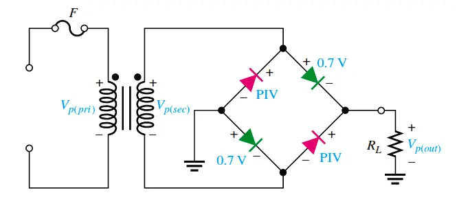
Figure 6. Practical Diode Model with PIV Calculation
The PIV for each diode in a full wave bridge rectifier is the maximum reverse voltage that the diode must block during operation. This value is equal to the peak AC voltage of the supply, which can be calculated by multiplying the RMS (root mean square) voltage by the square root of 2. For example, if the AC supply voltage is 230 volts, the peak voltage will be approximately 325 volts (230 × √2). Consequently, the PIV rating for each diode in the rectifier must be at least 325 volts to safely withstand this maximum voltage without failure.
In circuits where a transformer is used to step up or step down the input voltage, the PIV calculation must also account for the transformed voltage. For instance, if the transformer steps down the voltage to 120 volts AC, the peak voltage becomes approximately 170 volts (120 × √2), and the diodes should have a PIV rating of at least 170 volts. Ensuring that the PIV rating of each diode matches or exceeds the calculated peak voltage to prevent reverse leakage currents and protect the rectifier from damage caused by overvoltage conditions.
Selection and Durability of Diodes Based on PIV
Selecting diodes with an appropriate PIV rating is an important step in ensuring the long-term durability and reliability of a full wave bridge rectifier. Diodes with PIV ratings higher than the calculated peak voltage provide an added safety margin, making the circuit more robust against unexpected voltage spikes or surges in the AC supply. This safety buffer is great in industrial and high-power applications, where power fluctuations are more frequent and severe.
Using diodes with insufficient PIV ratings can lead to frequent failures, as the diodes may be unable to block reverse voltages during operation. Over time, this can cause overheating, damage to other components in the circuit, and even total rectifier failure. By contrast, diodes with appropriately rated or slightly over-specified PIV values help ensure that the rectifier can withstand operating conditions and extend its overall lifespan.
Impact on Rectifier Performance and Longevity

Figure 7. Full-Wave Bridge Rectifier Circuit and Output Waveform
The performance and longevity of a full wave bridge rectifier are heavily dependent on the PIV ratings of its diodes. When diodes with adequate PIV ratings are used, they contribute to the circuit's overall robustness, allowing it to function reliably even under challenging conditions. This reliability is great in applications power stability, such as medical equipment, communication systems, and industrial machinery.
If the diodes are correctly rated, they prevent reverse leakage currents and electrical breakdown, ensuring a steady and consistent DC output. This stability not only protects sensitive downstream components but also minimizes maintenance requirements and reduces the risk of costly system downtime. Additionally, proper PIV selection allows the rectifier to handle occasional surges or abnormal voltage fluctuations without compromising its integrity or efficiency.
Capacitor Filter in Full-Wave Bridge Rectifiers
The integration of a capacitor filter in full-wave bridge rectifiers is an improvement that enhances the quality of the output direct current (DC). Full-wave bridge rectifiers efficiently convert alternating current (AC) into DC, but the immediate output is not a smooth, steady DC. Instead, it is a pulsating DC waveform, characterized by periodic peaks and troughs. This fluctuation can cause issues for sensitive electronic devices that require a constant and stable voltage to function reliably. To address this limitation and improve the rectifier’s output, a capacitor filter is added. The capacitor’s ability to store and release electrical energy gradually helps smooth out these fluctuations, producing a cleaner and more stable DC voltage.

Figure 8. Full-Wave Rectifier with Capacitor Filter
Role and Mechanism of Capacitor Filters
The main purpose of the capacitor in a full-wave bridge rectifier is to reduce ripple and stabilize the output voltage. Ripple refers to the small, residual AC component that remains superimposed on the rectified DC output. This ripple occurs because the rectification process converts the alternating positive and negative halves of the AC waveform into pulsating DC but does not completely eliminate the voltage fluctuations. The capacitor filter works by charging to the peak voltage of the rectified waveform when the diodes are conducting and then discharging to maintain the voltage when the diodes are not conducting.
This charge-discharge mechanism ensures that the voltage across the load remains relatively constant, even when the rectified AC voltage drops between peaks. The capacitor fills the gaps between the pulses of rectified DC, smoothing out the waveform and reducing the ripple. The result is a much steadier DC output, which is need for powering sensitive electronic devices such as microcontrollers, sensors, and communication systems, where even minor voltage variations can lead to performance issues.
Enhancing Output Stability with Larger Capacitors
The capacitance value of the filter capacitor plays a role in determining the effectiveness of ripple reduction. A larger capacitor has a higher charge storage capacity, enabling it to maintain voltage levels more effectively during the non-conduction phases of the AC cycle. This increased storage capacity minimizes voltage drops between the peaks of the rectified output, resulting in a smoother and more stable DC waveform. The larger the capacitance, the better the capacitor can compensate for the fluctuations in the rectified voltage, reducing the ripple amplitude.
However, the selection of capacitor size involves trade-offs. While a larger capacitor can improve stability, it also takes up more physical space, increases costs, and may require longer charging times. Therefore, you must balance these factors, choosing a capacitor size that meets the specific requirements of the application. For high-precision electronic applications, such as medical equipment or laboratory instruments, larger capacitors are often preferred to ensure the highest level of voltage stability and performance.
Benefits
In a practical setup, the capacitor is connected parallel to the load, across the rectifier’s output terminals. This configuration allows the capacitor to act as a buffer, absorbing sudden changes in voltage and protecting the load from these fluctuations. By maintaining a stable output voltage, the capacitor filter enhances the performance of the rectifier and prevents damage to downstream components caused by exposure to inconsistent voltages. One of the benefits of capacitor filtering is the extended lifespan of electronic components. Devices subjected to ripple or fluctuating voltages tend to wear out faster, as the components are continually stressed by the variations. The smoother DC output provided by the capacitor filter reduces this stress, improving the reliability and durability of the overall system.
The improved voltage stability is especially great in applications like battery chargers, where precise and consistent voltage is required to charge batteries safely and efficiently. A fluctuating voltage could damage the battery or reduce its lifespan. Similarly, other electronic devices such as amplifiers, processors, and communication equipment depend on smooth DC power to function correctly. In these cases, the capacitor filter not only enhances the device’s performance but also ensures its long-term reliability.
Advantages of Full Bridge Rectifiers
Full bridge rectifiers are widely recognized for their numerous advantages, making them a preferred choice in various electronic applications. Their ability to efficiently convert alternating current (AC) into direct current (DC), combined with cost-effective and high-performance characteristics, makes them stand out compared to other rectifying methods. Below, we explore the primary benefits of full bridge rectifiers in greater detail.
Elimination of Center-Tap Transformer
One advantage of full bridge rectifiers is that they eliminate the need for a center-tap transformer, simplifying circuit design and reducing costs. A center-tap transformer, required in some rectifier configurations, such as center-tapped full-wave rectifiers, features a secondary winding with a midpoint connection (center tap). Designing and manufacturing such transformers can be complex and expensive, as the winding must be split evenly and precisely to ensure balanced performance.
By removing the requirement for a center tap, full bridge rectifiers streamline the circuit’s architecture. This simplification results in transformers that are easier and less costly to produce, as they no longer require the extra center-tap winding. Additionally, the absence of a center tap reduces the size and weight of the transformer, making full bridge rectifiers more suitable for compact and lightweight designs. As a result, these rectifiers offer both economic and practical advantages, especially in applications where cost and simplicity are key considerations.
Increased Output Voltage
Full bridge rectifiers take full advantage of both the positive and negative halves of the AC waveform, effectively doubling the frequency of the rectified output compared to half-wave rectifiers. This increased utilization of the AC signal leads to a higher DC output voltage for the same transformer secondary voltage. In contrast, half-wave rectifiers only use one half of the AC cycle, resulting in lower efficiency and output voltage.
This characteristic of full bridge rectifiers makes them ideal for applications where a higher DC output is required. By generating a more substantial and continuous DC voltage, full bridge rectifiers improve the efficiency of the power conversion process. This advantage is beneficial in devices such as power supplies for communication systems, industrial equipment, and battery charging circuits, where a higher and more consistent DC output enhances overall performance.
Lower Peak Inverse Voltage Requirements
Another advantage of full bridge rectifiers is their reduced Peak Inverse Voltage (PIV) requirements for the diodes. In a center-tapped full-wave rectifier, each diode must withstand the full peak voltage of the transformer’s secondary winding in reverse bias. However, in a full bridge rectifier, each diode only needs to block half of this peak voltage, as the voltage is shared across the diodes during operation.
This reduced voltage stress enables the use of diodes with lower PIV ratings, which are often less expensive than their high-PIV counterparts. By allowing to use more cost-effective diodes without sacrificing performance or reliability, full bridge rectifiers offer a clear economic benefit. This makes them a preferred choice in both low-cost consumer electronics and large-scale industrial systems, where minimizing expenses without compromising quality is essential.
Smoother DC Output and Higher Transformer Utilization Factor
One of the standout advantages of full bridge rectifiers is their ability to produce a smoother DC output. The rectified output of a full bridge rectifier has a lower ripple factor compared to half-wave rectifiers, which translates to a more stable and consistent DC voltage. This smoother output is important for sensitive electronic devices, such as microcontrollers, sensors, and communication equipment, which require stable power for reliable operation.
Additionally, full bridge rectifiers offer a higher Transformer Utilization Factor (TUF), a measure of how efficiently the transformer’s capacity is used to deliver power to the load. The full bridge configuration ensures that the transformer is active during both halves of the AC cycle, maximizing its power delivery capability. A higher TUF not only improves energy efficiency but also reduces the size and cost of the transformer, as its full potential is utilized. This combination of smoother DC output and better transformer utilization makes full bridge rectifiers an energy-efficient and practical choice for modern electronic systems.
Disadvantages of Full Bridge Rectifiers
Full bridge rectifiers are highly efficient and widely used in many applications due to their ability to utilize both halves of the AC waveform. However, they come with specific disadvantages that can affect their practicality in certain situations. Understanding these drawbacks is important for selecting the appropriate rectification method based on the needs of a given application. Below are the main disadvantages of full bridge rectifiers, explained in detail.
Increased Circuit Complexity and Cost
One of the disadvantages of a full bridge rectifier is its increased circuit complexity compared to simpler rectification methods, such as the half-wave rectifier. A full bridge rectifier requires four diodes to function, whereas a half-wave rectifier only needs one. The inclusion of these extra components makes the circuit design more intricate, requiring more connections and space. For compact electronic devices where minimizing circuit size is a priority, the larger size and increased number of components can pose design challenges.
The cost factor is another consideration. Each diode adds to the material expense, and the increased number of components raises the overall cost of production. Furthermore, a more complex design means more potential points of failure, which can complicate troubleshooting and maintenance. For industries or applications where cost-efficiency and simplicity are key, the added expense and complexity of a full bridge rectifier might make it less appealing.
Greater Voltage Drop in Output
In a full bridge rectifier, the current passes through two diodes during each half-cycle of the AC input. Each of these diodes introduces a forward voltage drop, which is around 0.7 volts for standard silicon diodes. As a result, the total voltage drop per cycle is approximately 1.4 volts. This drop is less in high-voltage applications but becomes a serious issue in low-voltage systems where preserving as much input voltage as possible is required.
The reduced output voltage caused by this voltage drop can negatively impact the overall efficiency of the rectifier, especially in scenarios where every fraction of voltage is important. For low-power or low-voltage devices, additional steps, such as voltage boosting, may be required to make the output usable. These extra stages not only increase the cost and complexity of the system but can also introduce further energy losses.
Compromised Efficiency Due to Voltage Drop
The voltage drop across the diodes does not just reduce the output voltage but also contributes to efficiency losses in the form of wasted energy. This energy is dissipated as heat, which does not contribute to powering the load but instead reduces the overall energy efficiency of the system. This loss is great in power-sensitive applications, such as battery-powered devices or renewable energy systems, where conserving energy is a top priority.
In high-efficiency designs, even small energy losses can add up over time, leading to higher operational costs and lower overall system performance. You must account for these losses when considering the use of a full bridge rectifier and may need to explore alternative rectification methods or more efficient diodes, such as Schottky diodes, to minimize the impact of voltage drops.
Increased Heat Dissipation and Thermal Management Needs
The heat generated by the voltage drop across the diodes introduces additional design challenges. As the current flows through the diodes, the energy lost as heat must be managed effectively to prevent overheating. In high-power applications or environments with limited cooling options, this becomes a concern. If the heat is not adequately dissipated, it can lead to thermal stress on the diodes, reducing their lifespan and reliability.
Thermal management solutions, such as heat sinks, fans, or advanced cooling systems, may be required to keep the rectifier operating within safe temperature limits. However, these measures add further cost and complexity to the system. Poor thermal management can accelerate the wear and tear of components, increasing the likelihood of system failures and necessitating more frequent maintenance or replacement.
Reliability and Maintenance Concerns
The reliance on four diodes in a full bridge rectifier introduces a degree of interdependence that can compromise the system’s reliability. The failure of any one diode disrupts the entire rectification process, leading to a loss of functionality. This makes it useful to use high-quality diodes and to design the circuit with adequate protection mechanisms, such as fuses or surge suppressors, to prevent damage caused by voltage spikes or other anomalies.
The need for regular maintenance to ensure all diodes are functioning correctly adds to the operational overhead. This is true in systems where downtime is not acceptable, such as industrial automation or medical equipment. In these cases, scheduled inspections and component replacements are needed to maintain consistent performance, increasing long-term costs and maintenance efforts.
Bridge Rectifier vs. Full Bridge Rectifier
The terms Bridge Rectifier and Full Bridge Rectifier are often used interchangeably and refer to the same rectifier configuration. Both describe a circuit that uses four diodes arranged in a bridge to convert alternating current (AC) into direct current (DC). This type of rectifier is a standard design in power electronics, known for its efficiency and ability to utilize the entire AC waveform for full-wave rectification. A Bridge Rectifier is any rectifier circuit that forms a bridge using its components to achieve full-wave rectification. The term Full Bridge Rectifier is more specific and highlights the standard design using four diodes. In most practical discussions, the two terms mean the same thing and are used to describe the same circuit. This design is favored because it converts both halves of the AC waveform into a unidirectional DC output, making it more efficient than half-wave rectifiers.
The full bridge rectifier is important in power supply circuits because it provides a stable and reliable DC output, which is necessary for the proper functioning of electronic devices. Its ability to maximize the use of the input AC signal while minimizing voltage loss makes it ideal for high-power applications. This configuration is commonly used in systems like computer power supplies, battery chargers, and other devices requiring clean and steady DC power. The main advantages of a full bridge rectifier include higher efficiency and increased output voltage compared to half-wave rectifiers. By utilizing both halves of the AC waveform, it doubles the output frequency, simplifying the filtering process needed to smooth the DC output. This design also enhances energy efficiency and ensures a more consistent output voltage, making it a preferred choice in modern power conversion systems. Bridge Rectifier and Full Bridge Rectifier refer to the same circuit used to convert AC to DC. This design is efficient, reliable, and widely used in power supply circuits for a variety of electronic devices. Its ability to provide steady DC power with minimal losses makes it a excellent component in modern electronics.
Half Bridge Rectifier vs. Full Bridge Rectifier
When comparing half bridge rectifiers and full bridge rectifiers, it is required to understand the differences in their design, operation, and performance. These distinctions affect their suitability for different applications, particularly in terms of output voltage, efficiency, and stability. While both rectifiers serve the same purpose, converting alternating current (AC) to direct current (DC) their configurations and behaviors vary, influencing their practical use in electronic systems.

Figure 9. Half-Wave, Full-Wave Center-Tap, and Full-Wave Bridge Rectifier Configurations
Configuration and Functioning
The full bridge rectifier, often simply called a bridge rectifier, consists of four diodes arranged in a bridge configuration. This design allows the rectifier to convert both the positive and negative halves of the AC input waveform into a unidirectional DC output. Regardless of whether the input is in the positive or negative half-cycle, two of the four diodes in the bridge conduct, ensuring that the polarity of the output remains constant. This ability to utilize the entire AC waveform results in greater efficiency and smoother output compared to other rectification methods.
In contrast, a half bridge rectifier employs only two diodes along with a center-tapped transformer. The center tap acts as a neutral point, splitting the transformer's secondary winding into two equal parts. During operation, one diode conducts during the positive half-cycle of the AC input, while the other diode conducts during the negative half-cycle. Because only one half of the AC waveform is used at a time, the output from a half bridge rectifier is less efficient, as it discards half of the available power.
While full bridge rectifiers eliminate the need for a center-tapped transformer, which simplifies the circuit design and reduces costs, half bridge rectifiers rely heavily on this center tap for operation. This reliance increases transformer design complexity and limits their efficiency in certain applications, making full bridge rectifiers the more practical choice for modern, high-performance circuits.
Output Voltage and Stability
A major advantage of the full bridge rectifier is its ability to utilize both halves of the AC waveform, which increases the output voltage. This also doubles the frequency of the rectified DC, resulting in a smoother output with fewer fluctuations or ripples. The reduced ripple voltage is important for sensitive electronic devices, such as computers, medical equipment, and communication systems, which require a stable and consistent DC supply to function reliably.
In contrast, the half bridge rectifier produces a lower output voltage because it uses only one half of the AC waveform during each cycle. This results in a more pulsating DC output with higher ripple content, which can cause instability and inefficiency in applications requiring a smooth power supply. The higher ripple voltage necessitates additional filtering components, such as capacitors, to smooth out the output, which can increase costs and complexity in systems. For applications that require a high and stable output, full bridge rectifiers are the preferred choice. However, in less demanding scenarios where minor fluctuations in voltage can be tolerated, half bridge rectifiers may suffice.
Efficiency and Transformer Utilization
The transformer utilization factor (TUF) is an important measure of how efficiently a rectifier uses the transformer’s capacity to deliver power to the load. Full bridge rectifiers have a higher TUF because they utilize both halves of the AC input waveform without requiring a center-tapped transformer. This makes them inherently more efficient, allowing for better power delivery and reduced energy losses.
In contrast, half bridge rectifiers often have a lower TUF due to their dependence on a center-tapped transformer. The center tap reduces the effective utilization of the transformer’s secondary winding, leading to increased energy losses. Designing a center-tapped transformer is more complex and costly, further reducing the overall cost-effectiveness of half bridge rectifiers in many scenarios. For high-power applications where efficiency and energy conservation are required, full bridge rectifiers outperform their half bridge counterparts. However, in simpler, low-power applications where efficiency is less of a concern, half bridge rectifiers may still be a viable option.
Suitability for Applications
Full bridge rectifiers are widely used in applications where high power, stable output, and reliability are important. These include industrial power supplies, battery chargers, renewable energy systems, and electronic devices that require consistent DC power. Their ability to produce a smooth and efficient output makes them useful in environments where performance and stability cannot be compromised.
On the other hand, half bridge rectifiers are more commonly found in low-power applications where cost and simplicity take precedence over efficiency. These applications include small household appliances, toys, and other devices where the impact of higher ripple voltage and lower output voltage is negligible. In such cases, the simplicity and lower cost of the half bridge rectifier make it a practical solution.
Full Wave Rectifier vs. Center Tap Rectifier
When comparing full wave rectifiers, specifically the bridge rectifier, to center tap rectifiers, understanding their differences in design, performance, and cost is required. These rectifiers achieve the same goal, converting AC to DC, but their configurations, efficiencies, and applications vary. By exploring their structural and operational nuances, we can determine which rectifier is better suited for specific needs, balancing factors like efficiency, reliability, and cost-effectiveness.

Figure 10. Full-Wave Bridge Rectifier vs. Center-Tap Rectifier Circuit Diagrams
Design and Structural Differences
The full wave bridge rectifier uses four diodes arranged in a bridge configuration to rectify both halves of the AC waveform. This design eliminates the need for a center-tapped transformer, which simplifies the circuit and reduces costs associated with transformer manufacturing. During operation, two diodes conduct current during the positive half-cycle of the AC input, while the other two diodes conduct during the negative half-cycle. This ensures that the entire AC waveform is used, resulting in efficient power conversion and a consistent polarity in the DC output.
On the other hand, the center tap rectifier relies on a transformer with a center tap on its secondary winding. This center tap serves as a neutral point that divides the transformer’s output into two equal halves, each of which is rectified by one of the two diodes in the circuit. During the positive half-cycle of the AC input, one diode conducts, while during the negative half-cycle, the other diode conducts. However, because the center tap effectively splits the transformer’s output, each diode in the center tap rectifier only rectifies half of the total voltage. This difference in design means that the bridge rectifier can use a simpler transformer without a center tap, which is advantageous for applications where cost and complexity are concerns. Meanwhile, the center tap rectifier's dependence on a specialized transformer makes it less versatile and potentially more expensive to implement.
Performance and Efficiency
In terms of performance, the full wave bridge rectifier is generally more efficient because it utilizes the entire AC waveform. By using all of the transformer’s secondary voltage, the bridge rectifier produces a higher DC output for the same transformer specifications compared to the center tap rectifier. This translates into better voltage conversion efficiency, a smoother DC output, and a higher average voltage. These characteristics make the bridge rectifier a better choice for applications requiring a stable and high DC output, such as power supplies for industrial equipment or sensitive electronic devices.
The center tap rectifier, while effective, is less efficient due to its design limitations. Since each diode only rectifies half of the transformer's output voltage, the overall DC output is lower for the same transformer input. The split transformer design and higher peak inverse voltage (PIV) requirements on the diodes contribute to energy losses and make the system less efficient. This lower efficiency and reduced output voltage make the center tap rectifier less suitable for high-demand applications where every bit of power must be optimized. Another aspect of performance is the ripple factor, which measures the amount of AC ripple superimposed on the DC output. Bridge rectifiers have a lower ripple factor, producing a smoother DC signal compared to center tap rectifiers. The smoother output from a bridge rectifier reduces the need for extensive filtering, further improving its efficiency and reliability.
Voltage Stress and Cost Implications
The voltage stress on the diodes in these two configurations is a factor in their cost and reliability. In a bridge rectifier, each diode is subjected to only half of the peak AC voltage during its non-conducting phase. This reduced voltage stress allows for the use of lower-rated diodes, which are less expensive and easier to source. The lower stress also reduces the likelihood of diode failure, enhancing the overall reliability and longevity of the rectifier.
In contrast, the center tap rectifier places higher voltage demands on its diodes. Each diode must block the full peak voltage of one half of the transformer’s output, requiring higher-rated and more robust diodes. These diodes are more expensive, increasing the overall cost of the rectifier. The higher voltage stress on the diodes generates more heat, necessitating better thermal management solutions, such as heat sinks, to prevent overheating and ensure reliable operation. This adds further complexity and cost to the system.
Application Suitability
The full wave bridge rectifier is well-suited for applications efficiency, high output voltage, and cost-effectiveness. Its ability to use a simpler transformer and lower-rated diodes makes it a preferred choice in modern electronics, including industrial power supplies, renewable energy systems, and battery charging circuits. Its smoother DC output and reduced ripple factor make it ideal for sensitive electronic devices that require stable and consistent power.
The center tap rectifier, while less efficient, may still find use in applications where a center-tapped transformer is already part of the design or where output voltage requirements are lower. It is commonly used in older designs or situations where the transformer’s output is naturally split, such as in audio equipment or specific legacy systems. However, its limitations in efficiency and cost make it less competitive in newer, more demanding applications.
Applications of Full-Wave Bridge Rectifiers
Full-wave bridge rectifiers play a role in a wide range of applications that require the conversion of alternating current (AC) to direct current (DC). Their ability to provide a smooth and stable DC output makes them great in many electronic systems, from powering small devices to supporting large-scale industrial machinery. Below are some of the most common applications of full-wave bridge rectifiers, explained in detail.
Battery Charging Circuits
Full-wave bridge rectifiers are an important component in battery charging circuits, which are widely used for charging portable devices such as smartphones, laptops, and power banks. In these circuits, the rectifier converts AC from the mains power supply into DC, which is the form of electricity batteries require for charging. By efficiently utilizing both halves of the AC waveform, the rectifier ensures a steady flow of DC power, reducing charging time and energy loss. This stable and consistent DC output is used for the safety and longevity of batteries. Irregular or pulsating DC could cause overheating or damage to the battery cells, whereas the smooth output from a full-wave bridge rectifier prevents these issues. These rectifiers are also found in battery charging systems for electric vehicles for ensuring optimal battery performance.
DC Power Supplies
DC power supplies are one of the most common applications of full-wave bridge rectifiers. These rectifiers are used in power adapters, industrial controls, and various electronic devices to convert AC input into a steady DC output. The rectified DC is further filtered and regulated to meet the specific voltage and current requirements of the connected devices. In industrial applications, full-wave bridge rectifiers are integral to systems that require consistent and reliable DC power, such as motor controllers, automation systems, and machine tools. The ability to provide a high, stable output makes these rectifiers great for powering sensitive equipment that could malfunction due to power fluctuations. They are widely used in household appliances, medical devices, and telecommunications systems, ensuring smooth operation and prolonged device life.
LED Driver Circuits
Full-wave bridge rectifiers are used in LED driver circuits, where they provide a stable DC supply for LED lighting systems. LEDs operate on DC power, and any fluctuations or ripples in the supply can cause flickering or even permanent damage to the LEDs. The rectifier converts the AC input into a consistent DC output, ensuring that the LEDs receive a steady current. This application is important in commercial and residential lighting systems, as well as in decorative LED strip lighting. The use of full-wave bridge rectifiers helps improve the lifespan and performance of LEDs, making them a key component in energy-efficient lighting solutions.
Uninterruptible Power Supplies (UPS)
In uninterruptible power supply (UPS) systems, full-wave bridge rectifiers play a role in converting AC to DC, which is then used to charge the backup battery. During a power outage, the stored DC energy in the battery is converted back to AC to maintain a continuous power supply. The rectifier's ability to provide a consistent and efficient DC output ensures that the battery remains fully charged and ready for use. This application is excellent in systems, uninterrupted power such as hospitals, data centers, and emergency systems. By maintaining a steady power flow, full-wave bridge rectifiers help prevent downtime and protect equipment from damage caused by sudden power interruptions.
Variable Lab-Bench Power Supply
In research and development laboratories, variable lab-bench power supplies rely on full-wave bridge rectifiers to provide adjustable DC output. These power supplies are used in experimental setups where precise control over voltage and current is required. The rectifier ensures that the input AC is converted into a smooth DC output, which is then regulated to meet the desired levels. This application is important in testing and prototyping electronic circuits, as it allows to simulate different operating conditions and fine-tune their designs. The high stability and flexibility provided by full-wave bridge rectifiers in laboratory environments.
Portable Device Chargers
Full-wave bridge rectifiers are a key component in portable device chargers, where they convert AC from the power outlet into DC suitable for charging devices. These rectifiers ensure that the DC output is stable and within the required voltage and current limits for efficient and safe charging. The rectifiers’ efficiency helps reduce energy waste, making chargers more eco-friendly and cost-effective. From smartphones and tablets to wireless earbuds and power tools, portable device chargers depend on the reliable performance of full-wave bridge rectifiers to deliver consistent power.
SCR-Based Full-Wave Rectifiers
In SCR-based rectification systems, full-wave bridge rectifiers employ Silicon Controlled Rectifiers (SCRs) to provide precise voltage and current control. These rectifiers are used in applications where variable DC output is required, such as in industrial machinery, motor speed controllers, and high-precision power supplies. The inclusion of SCRs allows for dynamic adjustment of the rectified voltage, making these systems versatile and suitable for applications requiring high precision. Full-wave bridge rectifiers in this configuration are commonly used in environments where load conditions vary, ensuring optimal performance and energy efficiency.
12V Supplies for LED Strips
Full-wave bridge rectifiers are widely used to provide regulated 12V DC power for LED strips. These lighting systems are commonly found in homes, offices, and decorative setups, where a consistent and reliable DC supply is need for proper operation. By converting mains voltage into a stable 12V DC output, the rectifier ensures that the LED strips operate without flickering or overheating. This application is important in energy-efficient lighting systems, as the rectifier helps improve the performance and lifespan of the LEDs.
UPS Systems
In addition to their role in converting AC to DC, full-wave bridge rectifiers are best in maintaining continuous power supply in UPS systems. By stabilizing the DC output used to charge the backup battery, these rectifiers help ensure that the UPS system can seamlessly switch to battery power during outages. This application is especially excellent in mission-critical environments, such as hospitals, airports, and financial institutions, where uninterrupted power is need for safety and operational continuity. The rectifier’s reliability and efficiency contribute to the overall performance and dependability of the UPS system.
Conclusion
The Full Bridge Rectifier is a key device in turning AC into DC with great efficiency. It makes full use of the electrical power available, which results in higher output and less energy loss. The detailed workings of this device involve managing the flow of electricity through its diodes and using transformers and capacitors to ensure the power output is smooth and stable. This is important not only for small electronics but also for heavy-duty applications in industry. Although it might be more complex and potentially more costly than simpler setups, its benefits like more power and better energy use make it a top choice for powering a variety of electronic systems.
About us
ALLELCO LIMITED
Read more
Quick inquiry
Please send an inquiry, we will respond immediately.
Frequently Asked Questions [FAQ]
1. Does a full bridge rectifier convert AC to DC?
Yes, a full bridge rectifier converts alternating current (AC) to direct current (DC). It uses four diodes arranged in a bridge configuration to ensure that both halves of the AC input are turned into DC output.
2. What is the maximum efficiency of a bridge rectifier?
The maximum efficiency of a bridge rectifier typically approaches 100% under ideal conditions. However, efficiencies are slightly lower due to voltage drops across the diodes and other resistive losses within the circuit. The voltage drop is typically around 0.7 volts per diode, affecting the overall efficiency.
3. What is the purpose of a full wave rectifier?
The purpose of a full wave rectifier is to convert the entire input waveform, both positive and negative halves, into a unidirectional (one-directional) output. This maximizes the utilization of the input AC signal, making it more efficient than a half-wave rectifier, which only uses one half of the AC cycle.
4. How do you know if your rectifier is bad?
To determine if a rectifier is malfunctioning, there are several diagnostic steps you can follow. Start by checking for the most obvious sign: no DC output at the rectifier's terminals. If there's no output, it likely indicates a failure in the rectification process. Employ a multimeter set to diode mode to test each diode in the bridge rectifier. A functioning diode will exhibit low resistance when forward-biased and high resistance when reverse-biased. Inspect the rectifier for any visible physical damage such as signs of overheating, distortion, or a burnt smell. These physical signs often suggest that the rectifier has sustained damage that may impair its functionality.
5. What are the different types of rectifiers?
Rectifiers can be categorized into several types based on their design and the number of phases of the AC supply they convert. A Half-Wave Rectifier uses a single diode to convert one half of the AC wave, effectively allowing only one half of the AC cycle to pass through. In contrast, a Full-Wave Rectifier utilizes two diodes and a transformer or four diodes in a bridge configuration without a transformer to convert both halves of the AC wave. The Bridge Rectifier is a specific type of full-wave rectifier that employs four diodes arranged in a bridge to efficiently convert AC to DC. Lastly, the Three-Phase Rectifier is designed for converting three-phase AC to DC, making it more suitable and efficient for industrial applications where three-phase power is commonly used.
EPM3064ATC44-10 CPLD: Features, Specifications, Applications, and ISP Programming
on February 6th
XC9536-5VQ44C CPLD: Features, Specifications, Applications and Architecture
on February 4th
Popular Posts
-

Complex Instruction Set Computers: How They Changed Computing?
on April 18th 147749
-

USB-C Pinout and Features
on April 18th 111901
-

Using Xilinx Unified Simulation Primitives: A Comprehensive Guide to FPGA Design and Simulation
on April 18th 111349
-

Power Supply Voltages in Electronics: Meaning of VCC, VDD, VEE, VSS, and GND
on April 18th 83714
-

RJ45 Connector Guide: Pinout, Wiring, Cable Types, and Uses
on January 1th 79502
-

The Ultimate Guide to Wire Color Codes in Modern Electrical Systems
The way our electrical systems use colors isn’t just for looks. Each wire color now indicates a specific function, making it easier to identify and handle electrical components correctly during ins...on January 1th 66866
-

Quality (Q) Factor: Equations and Applications
The quality factor, or 'Q', is important when checking how well inductors and resonators work in electronic systems that use radio frequencies (RF). 'Q' measures how well a circuit minimizes energy...on January 1th 63004
-

Purge Valve Guide: Function, Symptoms, Testing, and Replacement for Optimal Engine Performance
The purge valve is a key part of a car’s system that helps keep the air clean by managing fuel vapors before they can escape into the atmosphere. This not only helps the environment by reducing pol...on January 1th 62934
-

Achieving Peak Performance with the Maximum Power Transfer Theorem
The Maximum Power Transfer Theorem explains how energy from a source, such as a battery or generator, flows to a connected load. It shows the exact condition where the load receives the most power....on January 1th 54074
-

A23 Battery Specifications and Compatibility
The A23 battery is a small, cylinder-shaped battery with high voltage. Also called 23A, 23AE, or MN21, it runs at 12 volts and much higher than AA or AAA batteries. Its special design make...on January 1th 52087
HOT Part Number
-

XC3S50A-4VQG100C
AMD
IC FPGA 68 I/O 100VQFP
SI1102-A-GM
Silicon Labs
SENSOR OPT REFLECTIVE 50CM 8WDFN
TCN4-13+
Mini-Circuits
1:4 LTCC TRANSFORMER, 650 - 1250
VF30100S-E3/4W
Vishay General Semiconductor - Diodes Division
DIODE SCHOTTKY 100V 30A ITO220AB
GRM033R70J103KA01D
Murata Electronics
CAP CER 10000PF 6.3V X7R 0201
QMK212B7102MDHT
Taiyo Yuden
CAP CER 1000PF 250V X7R 0805
M82351G-12
MACOM Technology Solutions
ACCESS VOICE PROCESSOR
74LV132D,112
Nexperia USA Inc.
IC GATE NAND SCHMIT 4CH 2IN 14SO
AH1801-FJG-7
Diodes Incorporated
MAG SWITCH OMNIPOLAR DFN2020B-3
DG412DY-T1-E3
Vishay Siliconix
IC SWITCH SPST-NOX4 35OHM 16SOIC
PIC16F876A-I/SO
Microchip Technology
IC MCU 8BIT 14KB FLASH 28SOIC
LXA08FP600
Power Integrations
DIODE GP 600V 8A TO220 FULL PACK
FM25V20A-DG
Infineon Technologies
IC FRAM 2MBIT SPI 40MHZ 8DFN
CY7C1011CV33-10ZXC
Cypress Semiconductor Corp
IC SRAM 2MBIT PARALLEL 32TSOP II
04023C221KAT2A
KYOCERA AVX
CAP CER 220PF 25V X7R 0402
RO3101A
Murata Electronics
SAW RES 433.9200MHZ SMD
XRD9818ACGTR
MaxLinear, Inc.
IC AFE 3 CHAN 16BIT 28TSSOP
CL21F104ZBANNNC
Samsung Electro-Mechanics
CAP CER 0.1UF 50V Y5V 0805 -

BZT52-B16_R1_00001
Panjit International Inc.
SOD-123, ZENER
P0300ECL
Littelfuse Inc.
THYRISTOR 25V 400A TO226-2
TPS73615DBVTG4
Texas Instruments
IC REG LINEAR 1.5V 400MA SOT23-5
SN74AXC4T774BQBR
Texas Instruments
IC TRANSCEIVER HALF 4/4 16WQFN
170M5954
Eaton - Bussmann Electrical Division
FUSE SQUARE 350A 1KVAC RECT
CC0805KRX7R9BB682
YAGEO
CAP CER 6800PF 50V X7R 0805
SRP7028A-6R8M
Bourns Inc.
FIXED IND 6.8UH 4.5A 60 MOHM SMD
SMAJ150CA
Taiwan Semiconductor Corporation
TVS DIODE 150VWM 243VC DO214AC
PE-68675
Pulse Electronics
IC CHIP
MAX14890EATJ+
Analog Devices Inc./Maxim Integrated
IC RECEIVER 0/4 32TQFN
TFZGTR20B
Rohm Semiconductor
DIODE ZENER 20V 500MW TUMD2
1N5406-E3/73
Vishay General Semiconductor - Diodes Division
DIODE GEN PURP 600V 3A DO201AD
ME501610
Powerex Inc.
BRIDGE RECT 3P 1.6KV 100A MODULE
GRM1555C2A5R8DA01D
Murata Electronics
CAP CER 5.8PF 100V C0G/NP0 0402
MRF8S19140HSR3
NXP USA Inc.
FET RF 65V 1.96GHZ NI780HS
TN2130K1-G
Microchip Technology
MOSFET N-CH 300V 85MA TO236AB
ADL5519ACPZ-R7
Analog Devices Inc.
IC AMP LOG DETECT CTRLR 32LFCSP
SP3222ECT-L
MaxLinear, Inc.
IC TRANSCEIVER FULL 2/2 18SOIC -
502AT-2
Semitec USA Corp
NTC THERMISTORS 5KOHM 1%
NFM18CC101R1C3D
Murata Electronics
CAP FEEDTHRU 100PF 20% 16V 0603
PS2562L-1-F3-A
Renesas Electronics America Inc
OPTOISOLATOR 5KV DARL 4SMD
502494-0370
Affinity Medical Technologies - a Molex company
2.0 W/B SGL R/ARECASSY3CKTEMBSTP
C1206C223K5RACTU
KEMET
CAP CER 0.022UF 50V X7R 1206
NIS5102QP2HT1G
onsemi
IC HOT SWAP CTRLR GP 12PLLP
VI-J62-MY
Vicor Corporation
DC DC CONVERTER 15V 50W
ADR441ARMZ-REEL7
Analog Devices Inc.
IC VREF SERIES 0.12% 8MSOP
MIC5200-5.0BS
Microchip Technology
IC REG LINEAR 5V 100MA SOT223-3
TAS3251DKQR
Texas Instruments
IC AMP D MONO/STER 350W 56HSSOP
GRM1886T1H360JD01D
Murata Electronics
CAP CER 36PF 50V T2H 0603
TZM5249B-GS08
Vishay General Semiconductor - Diodes Division
DIODE ZENER 19V 500MW SOD80
LM2575-5.0YWM
Microchip Technology
IC REG BUCK 5V 1A 24SOIC
RT0402BRE075K6L
YAGEO
RES SMD 5.6K OHM 0.1% 1/16W 0402
C0603JB1A104M030BC
TDK Corporation
CAP CER 0.1UF 10V JB 0201
CSD17571Q2
Texas Instruments
MOSFET N-CH 30V 22A 6SON
P4SMA13CA
Bourns Inc.
TVS DIODE 11.1VWM 18.2VC DO214AC
AR0144ATSM20XUEA0-DPBR
onsemi
1MP 1/4 CIS SO