High Pass Filter: Working, Types, Advantages and Applications
In this guide, you’ll learn what a high-pass filter is and how it lets high-frequency signals pass while reducing low-frequency noise. You’ll see how it works, the difference between passive and active designs, and how first- and second-order filters affect signal strength. You’ll also understand how high-pass and low-pass filters compare. By the end, you’ll know where high-pass filters are commonly used in circuits.Catalog
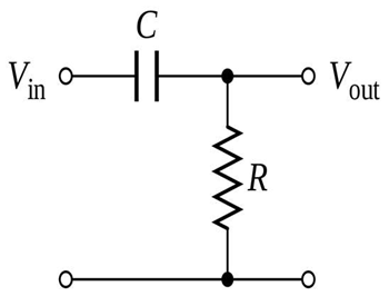
Figure 1. High Pass Filter Circuit
What is a High Pass Filter?
A high-pass filter (HPF) is a basic electronic circuit that lets high-frequency signals pass while reducing or blocking low-frequency signals. The figure above shows the simplest form of a passive high-pass filter, made from a capacitor (C) and a resistor (R). In this circuit, the input signal (Vin) first passes through the capacitor. Because a capacitor naturally blocks low frequencies and allows higher frequencies to move through more easily, only the higher-frequency parts of the signal reach the output (Vout). The resistor then provides a path to ground, helping shape the filter’s cutoff behavior.
How a High Pass Filter Works?

Figure 2. High Pass Filter Working Diagram
A high-pass filter works by blocking low-frequency signals and allowing higher-frequency signals to pass through the circuit. In the figure above, this behavior is shown clearly through the capacitor C1 and resistor R3. At low frequencies, C1 has high impedance, so most of the low-frequency content is dropped across the capacitor and routed to ground through R3. This prevents unwanted low-frequency noise from reaching the next stage.
As the input frequency increases, the impedance of C1 decreases. This allows high-frequency signals to pass through the high-pass filter stage and move toward the amplifier. In this active high-pass filter design, the operational amplifier then boosts or stabilizes the high-frequency portion of the signal using the feedback network formed by R1 and R2.
This entire process is controlled by the cutoff frequency, which determines the point where the filter starts reducing low-frequency signals. Frequencies above the cutoff pass more easily, resulting in a cleaner and more accurate high-frequency output.
Types of High Pass Filters
High-pass filters can be classified into two main categories based on circuit design.
Passive High Pass Filter
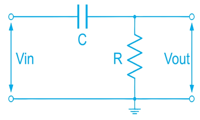
Figure 3. Passive High Pass Filter Circuit
A passive high-pass filter uses only passive components, most commonly a resistor (R) and capacitor (C) to block low frequencies and allow higher frequencies to pass. In the figure, the capacitor is placed in series with the input signal, while the resistor is connected to ground. This simple RC layout forms a high-pass filter because the capacitor resists low-frequency signals but easily passes high-frequency components. Since the circuit uses no external power source, it is stable and cost-effective, but it cannot amplify the signal. Passive high-pass filters are ideal for basic noise removal and general signal conditioning.
Active High Pass Filter
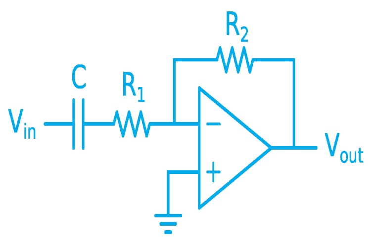
Figure 4. Active High Pass Filter Circuit
An active high-pass filter adds an operational amplifier (op-amp) to the basic RC structure for better control and performance. In the figure, the capacitor and resistor R1 create the high-pass filtering action, while the op-amp and feedback resistor R2 boost or shape the high-frequency output. This design provides adjustable gain, improved impedance matching, and a sharper frequency response compared to passive filters. Because of these advantages, active high-pass filters are widely used in audio circuits, sensor interfaces, and precision instrumentation where both filtering and amplification are needed.
Orders of High Pass Filters
High-pass filters are categorized by "order," which represents how steeply the filter attenuates frequencies below the cutoff point. Each order adds an additional reactive component, increasing roll-off rate and improving frequency selectivity.
First Order High Pass Filters
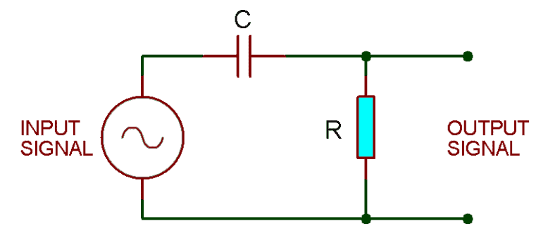
Figure 5. First-Order High Pass Filter Circuit
A first-order high-pass filter uses only one reactive component typically a single capacitor (C) to block low frequencies and pass higher frequencies. In the figure, the capacitor is placed in series with the input signal, followed by a resistor connected to ground. This simple RC configuration creates the first-order HPF behavior, producing a gradual roll-off of 20 dB per decade. Because of its basic structure, it offers smooth frequency transition and is ideal for simple noise removal or basic signal conditioning.
Second Order High Pass Filters
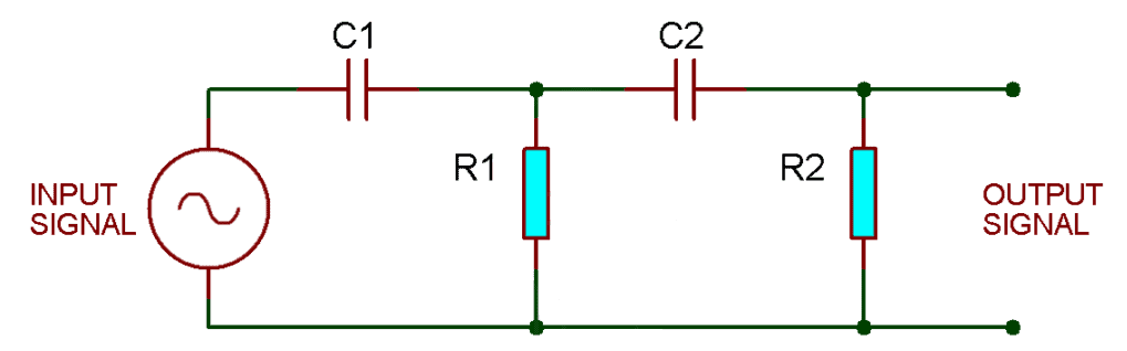
Figure 6. Second-Order High Pass Filter Circuit
A second-order high-pass filter includes two reactive components, such as the pair of capacitors C1 and C2 shown in the figure. Each capacitor forms a high-pass stage with its corresponding resistor (R1 and R2), creating a stronger filtering effect when combined. This design produces a steeper roll-off of 40 dB per decade, allowing much better suppression of unwanted low-frequency signals. Second-order HPFs are commonly used in audio processing, communication circuits, and applications requiring sharper frequency control.
Advantages and Limitations of High Pass Filters
Advantages
• Simple design and easy to implement
• Effective removal of low-frequency noise
• Stable performance across wide frequency ranges
• Active HPFs can provide gain and improved signal control
• Useful in both analog and digital signal applications
Limitations
• Passive filters cannot amplify signals
• Performance may degrade with component tolerances
• Active filters require external power
• High-order filters can become complex and costly
• May introduce phase shift in certain applications
High Pass Filter vs. Low Pass Filter
High-pass filters and low-pass filters are two of the most commonly used frequency filters in electronics. The table below shows their main differences in an easy way.
|
Specification |
High Pass
Filter (HPF) |
Low Pass
Filter (LPF) |
|
Main
Function |
Passes
high-frequency signals; blocks low frequencies |
Passes
low-frequency signals; blocks high frequencies |
|
Cutoff
Frequency Behavior |
Allows
signals above the cutoff |
Allows
signals below the cutoff |
|
Typical
Use |
Removes
rumble, hum, DC offset, and low-frequency noise |
Removes
high-frequency noise, spikes, and interference |
|
Reactive
Component Role |
Capacitor
blocks low frequencies and passes high frequencies |
Capacitor
passes low frequencies and blocks high frequencies |
|
Signal
Direction Effect |
Improves
clarity of high-frequency components |
Smooths and
stabilizes low-frequency signals |
|
Roll-Off
Slope (1st Order) |
20 dB/decade
downward from high to low |
20 dB/decade
upward from low to high |
|
Time-Domain
Effect |
Emphasizes
fast changes in the signal |
Emphasizes
slow changes in the signal |
|
Applications |
Audio
filtering, RF coupling, sensor calibration |
Power
supplies, anti-aliasing, smoothing circuits |
|
Output
Behavior |
Output
increases with frequency |
Output
decreases with frequency |
|
Circuit
Examples |
RC, LC, and
op-amp high-pass filters |
RC, LC, and
op-amp low-pass filters |
Applications of High Pass Filters
Audio Processing
High-pass filters remove low-frequency noise such as rumble and wind. This helps keep the audio signal clean and clear. They are widely used in microphones, speakers, and mixing systems to improve overall sound quality.
Communication Systems
High-pass filters allow important high-frequency information to pass through the communication line. They help reduce unwanted low-frequency interference that can distort the signal. This results in clearer transmission and better separation of communication channels.
Power Electronics
In power electronics, high-pass filters shape PWM signals for smoother switching. They also help remove switching noise produced by converters and inverters. This improves system stability and ensures cleaner output signals.
Sensors and Instrumentation
High-pass filters remove DC offset and slow drift in sensor readings. This helps focus on the actual changing part of the signal. As a result, measurements become more accurate and easier to analyze.
Image Processing (Conceptual HPFs)
Conceptual high-pass filters highlight sharp changes in an image, such as edges. They help enhance contrast and fine details. This makes them useful for sharpening images and improving visual clarity.
Radio and RF Applications
High-pass filters block unwanted DC components in RF circuits. They allow high-frequency radio signals to pass through efficiently. These filters are important in coupling and decoupling networks for stable RF operation.
Conclusion
High-pass filters help clean signals by blocking low frequencies and letting higher ones through. Different types and orders offer various levels of filtering strength. Knowing how they work, along with their pros and cons, makes it easier to choose the right filter for each application. They remain useful in many systems, from audio and communication to power electronics and sensing devices.
About us
ALLELCO LIMITED
Read more
Quick inquiry
Please send an inquiry, we will respond immediately.
Frequently Asked Questions [FAQ]
1. Can I customize the cutoff frequency of a high-pass filter?
Yes. You can adjust the cutoff frequency by choosing different resistor and capacitor values. Some active HPFs also let you fine-tune frequency and gain through the op-amp’s feedback network.
2. Can I use a high-pass filter with my existing amplifier or audio setup?
Yes. Just make sure the cutoff frequency matches the range you want to filter, and check that your amplifier’s input impedance works well with the HPF design. This prevents unwanted signal loss.
3. What happens if I choose the wrong cutoff frequency?
If the cutoff is too high, you’ll lose important parts of the signal. If it’s too low, unwanted noise will still pass through. Choosing the right value is key to getting clear and accurate output.
4. Are high-pass filters compatible with digital circuits and microcontrollers?
Yes. They are commonly used to remove DC offset and clean signals before feeding them into ADCs, sensors, and microcontroller inputs. Just make sure the filter does not distort the useful portion of the signal.
5. Is it difficult to install or integrate a high-pass filter into my circuit?
No. Most HPFs are easy to add, especially simple RC versions. Active HPFs may require proper power supply connections, but they’re still straightforward if you follow the circuit diagram.
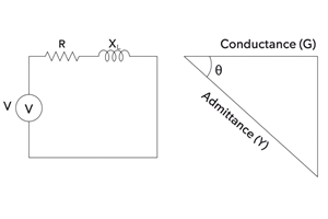
What is Admittance: Complete Guide to Formula, Units, and AC Circuit Analysis
on December 8th
Carbon Resistor Explained: Types, Construction, Color Code and Applications
on December 5th
Popular Posts
-

Complex Instruction Set Computers: How They Changed Computing?
on April 18th 147754
-

USB-C Pinout and Features
on April 18th 111931
-

Using Xilinx Unified Simulation Primitives: A Comprehensive Guide to FPGA Design and Simulation
on April 18th 111349
-

Power Supply Voltages in Electronics: Meaning of VCC, VDD, VEE, VSS, and GND
on April 18th 83718
-

RJ45 Connector Guide: Pinout, Wiring, Cable Types, and Uses
on January 1th 79505
-

The Ultimate Guide to Wire Color Codes in Modern Electrical Systems
The way our electrical systems use colors isn’t just for looks. Each wire color now indicates a specific function, making it easier to identify and handle electrical components correctly during ins...on January 1th 66873
-

Quality (Q) Factor: Equations and Applications
The quality factor, or 'Q', is important when checking how well inductors and resonators work in electronic systems that use radio frequencies (RF). 'Q' measures how well a circuit minimizes energy...on January 1th 63010
-

Purge Valve Guide: Function, Symptoms, Testing, and Replacement for Optimal Engine Performance
The purge valve is a key part of a car’s system that helps keep the air clean by managing fuel vapors before they can escape into the atmosphere. This not only helps the environment by reducing pol...on January 1th 62960
-

Achieving Peak Performance with the Maximum Power Transfer Theorem
The Maximum Power Transfer Theorem explains how energy from a source, such as a battery or generator, flows to a connected load. It shows the exact condition where the load receives the most power....on January 1th 54080
-

A23 Battery Specifications and Compatibility
The A23 battery is a small, cylinder-shaped battery with high voltage. Also called 23A, 23AE, or MN21, it runs at 12 volts and much higher than AA or AAA batteries. Its special design make...on January 1th 52101
HOT Part Number
-
7443551181
Würth Elektronik
FIXED IND 18UH 7.5A 22 MOHM SMD
LM4040C50IDCKR
Texas Instruments
IC VREF SHUNT 0.5% SC70-5
TPS76338DBVR
Texas Instruments
IC REG LINEAR 3.8V 150MA SOT23-5
MC908GZ32MFAE
NXP USA Inc.
IC MCU 8BIT 32KB FLASH 48LQFP
MUR1620CT
onsemi
DIODE ARRAY GP 200V 8A TO220AB
CA3140T
Rochester Electronics, LLC
IC OPAMP GP 1 CIRCUIT TO99-8
ISL6217ACV-T
Renesas Electronics America Inc
IC REG CTRLR INTEL 1OUT 38TSSOP
MMDF2P02ER2G
onsemi
MOSFET 2P-CH 25V 2.5A 8SOIC
MAX17543ATP+
Analog Devices Inc./Maxim Integrated
IC REG BUCK ADJ 2.5A 20TQFN
FTR-110-03-G-D-LC-06
Samtec Inc.
CONN HEADER SMD 20POS 1.27MM
HMC826LP6CETR
Analog Devices Inc.
IC PLL W/VCO FRACTIONAL-N 40SMD
NJM386M
Nisshinbo Micro Devices Inc.
IC AUDIO PWR AMP BIPO LV 8DMP
P6SMB12AT3
onsemi
TVS DIODE 10.2VWM 16.7VC SMB
BD82001FVJ-E2
Rohm Semiconductor
IC PWR SWITCH N-CHAN 1:1 8TSSOP
TLE2142ACD
Texas Instruments
IC OPAMP GP 2 CIRCUIT 8SOIC
2225SC101KAT1A\SB
KYOCERA AVX
CAP CER 100PF 1.5KV X7R 2225
AON6414AL
Alpha & Omega Semiconductor Inc.
MOSFET N-CH 30V 13A/30A 8DFN
0452001.MRL
Littelfuse Inc.
FUSE BRD MNT 1A 125VAC/VDC 2SMD -

P6SMB550A
Bourns Inc.
TVS DIODE 495VWM 760VC DO214AA
PIC18F23K20T-I/SS
Microchip Technology
IC MCU 8BIT 8KB FLASH 28SSOP
GRM1555C1H5R1BA01D
Murata Electronics
CAP CER 5.1PF 50V C0G/NP0 0402
MC9S08AC60MPUE
NXP USA Inc.
IC MCU 8BIT 60KB FLASH 64LQFP
KA317TU
onsemi
IC REG LIN POS ADJ 1.5A TO220-3
DMP2120U-13
Diodes Incorporated
MOSFET P-CH 20V 3.8A SOT23 T&R 1
CD74HC30M96
Texas Instruments
IC GATE NAND 1CH 8-INP 14SOIC
PIC16F570T-I/SS
Microchip Technology
IC MCU 8BIT 3KB FLASH 28SSOP
NE5230DG
onsemi
IC OPAMP GP 1 CIRCUIT 8SOIC
BCM33843ZUKFSBGB0T
Broadcom Limited
CABLE MODEM
06035C682KAT7A
KYOCERA AVX
CAP CER 6800PF 50V X7R 0603
BCR135SH6327XTSA1
Infineon Technologies
TRANS 2NPN PREBIAS 0.25W SOT363
CD74AC151M96
Texas Instruments
IC MULTIPLEXER 1 X 8:1 16SOIC
MAX44267AUD+
Analog Devices Inc./Maxim Integrated
IC OPAMP GP 2 CIRCUIT 14TSSOP
MB85RC16PNF-G-JNERE1
Kaga FEI America, Inc.
IC FRAM 16KBIT I2C 1MHZ 8SOP
HLMP-1401
Broadcom Limited
LED YELLOW DIFFUSED T-1 T/H
UCC2580D-4
Unitrode
IC OFFLINE SW MULT TOP 16SOIC
87832-0826
Molex
MGRID HDR SHRD SMT /LCK/CAP .38A -
UCC25705DGKTRG4
Texas Instruments
IC REG CTRLR MULT TOP 8VSSOP
FMMT3906TA
Diodes Incorporated
TRANS PNP 40V 0.2A SOT23-3
STU40N2LH5
STMicroelectronics
MOSFET N-CH 25V 40A IPAK
FSAM10SH60
onsemi
IC SMART POWER MOD 10A SPM32-AA
RT0603FRE071KL
Yageo
RES SMD 1K OHM 1% 1/10W 0603
ZX62-B-5PA(33)
Hirose Electric Co Ltd
CONN RCPT USB2.0 MICRO B SMD R/A
GBPC3506-E4/51
Vishay General Semiconductor - Diodes Division
BRIDGE RECT 1PHASE 600V 35A GBPC
SQA401EEJ-T1_GE3
Vishay Siliconix
MOSFET P-CH 20V 2.68A PPAK SC70
XC6221A182MR-G
Torex Semiconductor Ltd
IC REG LINEAR 1.8V 200MA SOT25
IRFH4210TRPBF
Infineon Technologies
MOSFET N-CH 25V 45A PQFN
L78L05ACD
STMicroelectronics
IC REG LINEAR 5V 100MA 8SO
04023J2R7BBSTR
KYOCERA AVX
CAP THIN FILM 2.7PF 25V 0402
C0603C0G1E750J
TDK Corporation
CAP CER 75PF 25V C0G 0201
SA20CA-E3/73
Vishay General Semiconductor - Diodes Division
TVS DIODE 20VWM 32.4VC DO204AC
PLL1705S1DBQR
Texas Instruments
PROTOTYPE
2SA2071T100Q
Rohm Semiconductor
TRANS PNP 60V 3A MPT3
XF3H-3555-31AR
Omron Electronics Inc-EMC Div
CONN FPC BOTTOM 35POS 0.3MM R/A
CY7C0851AV-133BBI
Infineon Technologies
IC SRAM 2MBIT 133MHZ 172FBGA