
How To Identify Capacitor Polarity Correctly And Safely
Working with capacitors becomes much easier when you understand how polarity is marked and why terminal orientation matters. You may come across different symbols, stripes, lead lengths, and circuit board markings that help identify the positive and negative terminals.Catalog
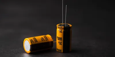
Figure 1. Polarized Electrolytic Capacitors
How to Identify Capacitor Positive and Negative Sides
In most polarized capacitors, the positive and negative terminals must be installed in the correct direction.
|
Capacitor Type |
Positive Side |
Negative Side |
Notes |
|
Radial aluminum electrolytic capacitor |
Longer lead is usually positive |
Stripe usually marks negative |
Check before the leads are trimmed |
|
SMD aluminum electrolytic capacitor |
Usually opposite the negative stripe |
Stripe often marks negative |
Always confirm the package marking |
|
Tantalum capacitor |
Bar or + mark usually indicates positive |
Opposite side is negative |
This differs from many aluminum
electrolytic capacitors |
|
Ceramic capacitor |
No polarity |
No polarity |
Can usually be installed either way |
|
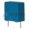
Film capacitor |
Usually no polarity |
Usually no polarity |
Special types should still follow the
datasheet |
A capacitor should not be installed based on only one clue when markings are unclear. For safer assembly, compare the capacitor body marking, PCB marking, schematic, and datasheet before applying power.
Which Capacitors Have Polarity
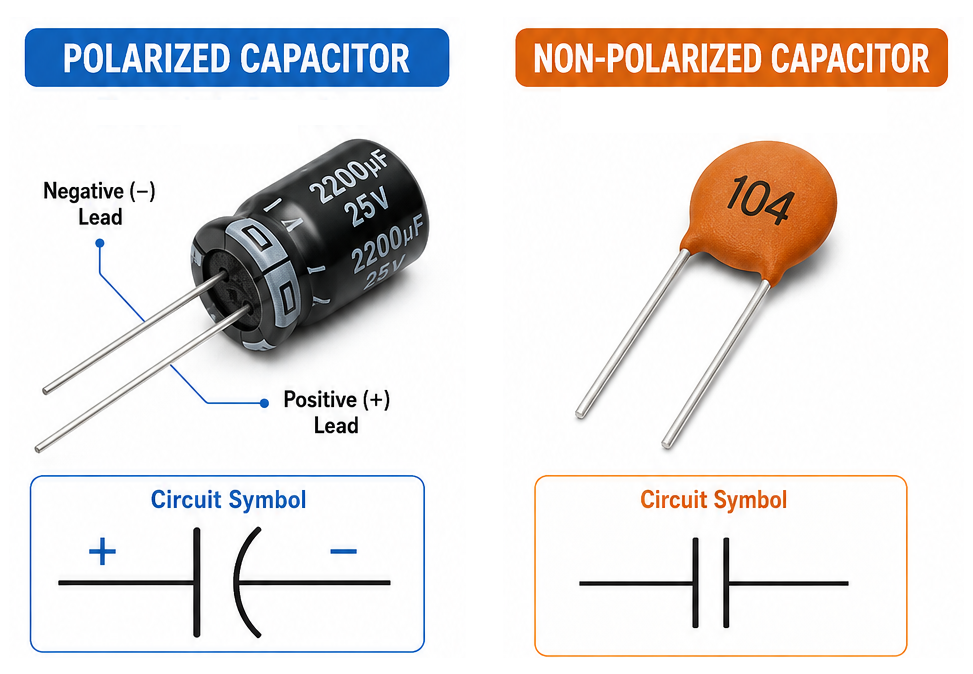
Figure 4. Polarized and Non-Polarized Capacitors Comparison
Some capacitors require a fixed terminal orientation, while others can operate in either direction. Polarized capacitors are normally used where relatively high capacitance is needed in a compact package. Non-polarized capacitors are commonly used in coupling, filtering, timing, RF, and AC signal applications where terminal direction is not fixed.
|
Capacitor Type |
Polarity Required |
Common Identification Method |
Typical Use |
|
Aluminum electrolytic capacitor |
Yes |
Negative stripe, lead length, PCB + mark |
Power filtering, smoothing, bulk energy
storage |
|
Tantalum capacitor |
Yes |
Positive bar, + mark, package marking |
Compact power filtering and decoupling |
|
SMD electrolytic capacitor |
Yes |
Stripe, printed mark, package symbol |
Surface-mount power circuits |
|
Ceramic capacitor |
Usually no |
No polarity marking |
Decoupling, bypassing, filtering |
|
Film capacitor |
Usually no |
No polarity marking |
AC signal circuits, filtering, timing |
|
Supercapacitor |
Usually yes |
+ and - markings |
Backup power and energy storage |
Most ceramic and film capacitors are non-polarized, but special capacitor types should still be checked against the datasheet. If the capacitor body has a clear + or - symbol, polarity must be followed.
Capacitor Polarity Markings by Type
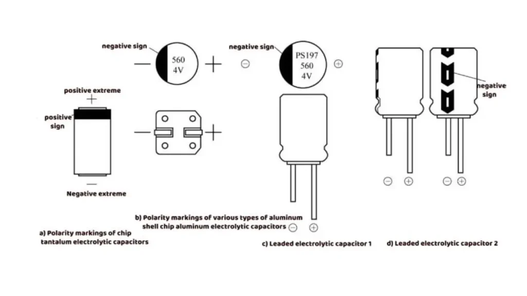
Figure 2. Capacitor Polarity Markings
Lead Length
Many new through-hole polarized capacitors use lead length to identify polarity. The longer lead is usually the positive terminal, while the shorter lead is usually the negative terminal. This method is only useful before the leads are trimmed.
Plus and Minus Symbols
Some capacitors print + or - symbols on the body or package. A + mark identifies the positive terminal, while a - mark identifies the negative terminal. These markings provide one of the clearest ways to identify polarity.
Stripe, Band, Bar, and Notch Markings
Electrolytic capacitors often use a stripe or band to mark one side of the component. On many aluminum electrolytic capacitors, the stripe marks the negative terminal. On many tantalum capacitors, a bar or + marking identifies the positive terminal. Since marking styles vary by manufacturer and package type, the datasheet should be checked if the marking is unclear.
Aluminum Electrolytic vs Tantalum Capacitor Polarity Markings
|
Capacitor Type |
Common Stripe / Bar Meaning |
Risk |
|
Aluminum electrolytic capacitor |
Stripe commonly marks the negative
terminal |
Reversing polarity can cause leakage,
heating, venting, or failure |
|
Tantalum capacitor |
Bar or + marking commonly identifies the
positive terminal |
Reverse installation may cause severe
failure or short circuit |
|
SMD package capacitors |
Marking style varies by manufacturer |
Always confirm with the datasheet or
original part marking |
How to Identify Capacitor Polarity on a PCB
Common PCB polarity indicators include:
• + symbol near the positive pad
• - symbol near the negative pad
• Polarity stripe printed on the silkscreen
• Shaded or filled pad marking
• Component outline showing capacitor orientation
• Reference designator and schematic connection
PCB markings should be compared with the capacitor body marking before soldering. If the board marking is damaged, missing, or unclear, check the schematic, BOM, or the original component orientation before replacing the capacitor.
How To Verify Capacitor Polarity Before Powering A Circuit
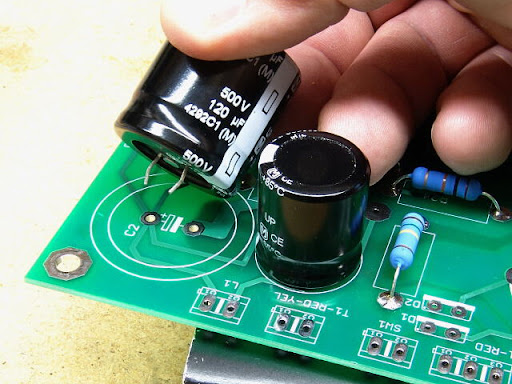
Figure 3. Verifying Capacitor Polarity on a Circuit Board
|
Step |
What to Check |
Why It Matters |
|
Step 1 |
Confirm whether the capacitor is
polarized |
Non-polarized capacitors usually do not
require orientation checking |
|
Step 2 |
Check the capacitor body for stripe, +
mark, bar mark, notch, or lead length difference |
Body markings give the first polarity
clue |
|
Step 3 |
Compare the capacitor marking with the
PCB polarity marking |
The installed direction must match the
board layout |
|
Step 4 |
Check the schematic or BOM if the board
marking is unclear |
Documentation can confirm the intended
connection |
|
Step 5 |
Use a multimeter to identify ground or
supply rail connections when needed |
This helps verify polarity on damaged or
unmarked boards |
|
Step 6 |
Confirm capacitance value, voltage
rating, package type, and polarity before soldering |
A correct polarity check is not enough if
the part rating is wrong |
|
Step 7 |
Do not power the circuit until
orientation is confirmed |
Powering a reversed polarized capacitor
can damage the component or circuit |
Before touching or replacing capacitors in a powered system, always make sure the circuit is disconnected from power and the capacitor is safely discharged. High-voltage capacitors can store dangerous energy even after the device is turned off.
Common Capacitor Polarity Mistakes
Polarity-related problems are often caused by incorrect installation, misread markings, wrong replacement parts, or unclear PCB symbols.
|
Mistake or Cause |
What Happens |
Potential Damage |
Recommended Fix |
|
Capacitor installed backwards |
Capacitor operates outside its intended
polarity |
Heating, leakage, venting, or failure |
Reinstall with correct polarity |
|
Misread polarity markings |
Incorrect terminal connection |
Circuit malfunction or unstable operation |
Verify all body and PCB markings before
installation |
|
Aluminum electrolytic and tantalum
markings confused |
Stripe or bar is interpreted incorrectly |
Reverse installation or short-circuit
risk |
Check capacitor type before installation |
|
Wrong capacitor type used |
Component characteristics do not match
circuit requirements |
Filtering, timing, or power stability
issues |
Replace with the specified capacitor type |
|
PCB polarity indicators ignored |
Capacitor orientation does not match
board design |
Assembly errors and troubleshooting
difficulty |
Follow PCB markings and schematic
references |
|
Damaged capacitor reused |
Existing defects remain in the circuit |
Reduced performance or premature failure |
Replace with a new qualified component |
|
Leads trimmed before polarity is checked |
Lead length can no longer identify
polarity |
Higher chance of installation error |
Check polarity before cutting leads |
About us
ALLELCO LIMITED
Read more
Quick inquiry
Please send an inquiry, we will respond immediately.
Frequently Asked Questions [FAQ]
1. How can capacitor polarity be identified when the leads have already been trimmed?
Polarity can usually be identified using printed symbols, stripes, bands, notches, or markings on the capacitor body. Circuit board markings may also provide additional orientation information.
2. Are all capacitors required to follow polarity markings?
No. Only polarized capacitors have designated positive and negative terminals. Non-polarized capacitors can generally be connected in either direction.
3. What information on a circuit board helps determine capacitor orientation?
Many circuit boards include plus and minus symbols, polarity bands, terminal labels, or component outlines that indicate the intended capacitor orientation.
4. When should a capacitor datasheet be consulted?
A datasheet is useful when component markings are unclear, when replacing a capacitor with a different part, or when verifying terminal orientation on unfamiliar capacitor types.
5. What is the main difference between polarized and non-polarized capacitors?
Polarized capacitors require a defined terminal orientation, while non-polarized capacitors do not. This difference influences how each type is selected and used within a circuit.
HC-05 Bluetooth Module Guide: Features, AT Commands, and Arduino Projects
on June 2th
LM35 Temperature Sensor: Pin Configuration, Operation, and Applications
on May 31th
Popular Posts
-

Complex Instruction Set Computers: How They Changed Computing?
on June 14th 148402
-

USB-C Pinout and Features
on June 14th 131612
-

Using Xilinx Unified Simulation Primitives: A Comprehensive Guide to FPGA Design and Simulation
on June 14th 111884
-

Power Supply Voltages in Electronics: Meaning of VCC, VDD, VEE, VSS, and GND
on June 14th 94454
-

RJ45 Connector Guide: Pinout, Wiring, Cable Types, and Uses
on January 1th 93984
-

The Ultimate Guide to Wire Color Codes in Modern Electrical Systems
The way our electrical systems use colors isn’t just for looks. Each wire color now indicates a specific function, making it easier to identify and handle electrical components correctly during ins...on January 1th 76891
-

Quality (Q) Factor: Equations and Applications
The quality factor, or 'Q', is important when checking how well inductors and resonators work in electronic systems that use radio frequencies (RF). 'Q' measures how well a circuit minimizes energy...on January 1th 74842
-

Purge Valve Guide: Function, Symptoms, Testing, and Replacement for Optimal Engine Performance
The purge valve is a key part of a car’s system that helps keep the air clean by managing fuel vapors before they can escape into the atmosphere. This not only helps the environment by reducing pol...on January 1th 68783
-
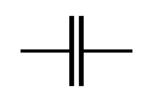
Understanding Capacitors and Their Symbols in Circuit Diagrams
Capacitors are small parts used in almost all electronic devices. They store and release electrical energy and are found in things like power supplies, radios, and circuits that help reduce noise. ...on June 14th 58527
-

A23 Battery Specifications and Compatibility
The A23 battery is a small, cylinder-shaped battery with high voltage. Also called 23A, 23AE, or MN21, it runs at 12 volts and much higher than AA or AAA batteries. Its special design make...on January 1th 58132
HOT Part Number
-
ADAU1978WBCPZ
Analog Devices Inc.
IC ADC 24BIT 192K 40LFCSP-WQ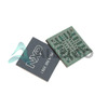
MIMX8MM1CVTKZAA
NXP USA Inc.
IC MPU I.MX 8M MINI SOLOLITE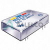
REC10-2405S/H3/M
Recom Power
DC DC CONVERTER 5V 10W
SBR20100CTFP
Diodes Incorporated
DIODE ARRAY SBR 100V 10A ITO220
SN74LS640NSR
Texas Instruments
IC TRANSCEIVER INVERT 5.25V 20SO
PM8371-BI
PMC-Sierra
PM8371-BI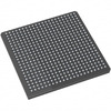
M2S025-FGG484
Microchip Technology
IC SOC CORTEX-M3 166MHZ 484FBGA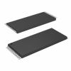
AT28C010-20TI
Microchip Technology
IC EEPROM 1MBIT PARALLEL 32TSOP
EP1C12F324C6N
Intel
IC FPGA 249 I/O 324FBGA
MC74VHCT373ADTRG
onsemi
IC LATCH TRANSP OCT 2ST 20-TSSOP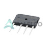
GBO25-12NO1
IXYS
BRIDGE RECT 1P 1.2KV 25A 4SIP
NCP302LSN20T1G
onsemi
IC SUPERVISOR 1 CHANNEL 5TSOP
SI3210-KT
Skyworks Solutions Inc.
IC TELECOM INTERFACE 38TSSOP
ADAU1787BCBZRL
Analog Devices Inc.
4 ADC, 2 DAC LOW POWER CODEC, AU
74VHC164MTCX
onsemi
IC SHIFT REGISTER 8BIT 14TSSOP
DAN222M3T5G
onsemi
DIODE ARRAY GP 80V 100MA SOT723
DG9451EN-T1-E4
Vishay Siliconix
IC MUX 8:1 105OHM 16MINIQFN
NPX-C01767
Amphenol NovaSensor
SENSOR PRES -

AOT5B65M1
Alpha & Omega Semiconductor Inc.
IGBT 650V 5A TO220
MPC508AU
Texas Instruments
IC MUX 8:1 1.5KOHM 16SOIC
TMS320DM355DZCE135
Texas Instruments
IC DGTL MEDIA SOC 337NFBGA
EFR32BG22C112F352GM32-CR
Silicon Labs
BLUE GECKO, QFN32, SECURE BOOT W
JMK105C6225MV-F
Taiyo Yuden
CAP CER 2.2UF 6.3V X6S 0402
MAX4481AXT+T
Analog Devices Inc./Maxim Integrated
IC OPAMP GP 1 CIRCUIT SC70-6
8A35001B-001AJG
Renesas Electronics America Inc
NETWORK TIMING
ACH3218-151-TD01
TDK Corporation
FILTER LC(T) SMD
VI-JND-IY
Vicor Corporation
DC DC CONVERTER 85V 50W
2204740-1
TE Connectivity AMP Connectors
CONN SPRING SLIDING BUS 2POS PCB
TAS5142DDVRG4
Texas Instruments
IC AMP CLSS D STER 100W 44HTSSOP
PC451J00000F
SHARP/Socle Technology
OPTOISOLATOR 3.75KV TRANS 4SMD
GRM1557U1H8R6DZ01D
Murata Electronics
CAP CER 8.6PF 50V U2J 0402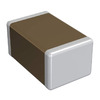
GRM2196P2A220JZ01D
Murata Electronics
CAP CER 22PF 100V P2H 0805
R5F51116ADFL#3A
Renesas Electronics America Inc
IC MCU 32BIT 256KB FLASH 48LFQFP
SN65LVDS050PWR
Texas Instruments
IC TRANSCEIVER FULL 2/2 16TSSOP
VI-J6Z-MZ
Vicor Corporation
VI-J6Z-MZ 300V 2V 5A
LM4041DIM7-1.2
Texas Instruments
IC VREF SHUNT 1% SC70-5 -
B32522N6684K289
EPCOS - TDK Electronics
CAP FILM 0.68UF 10% 450VDC RAD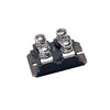
CLA110MB1200NA
IXYS
MOD THYRISTOR DUAL 1200V SOT-227
RT6200GE
Richtek USA Inc.
IC REG BUCK ADJ 600MA SOT23-6
MAX17501GATB+T
Analog Devices Inc./Maxim Integrated
IC REG BUCK ADJ 500MA 10TDFN
PZTA64
Fairchild Semiconductor
SMALL SIGNAL BIPOLAR TRANSISTOR,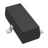
DRV5013ADEDBZRQ1
Texas Instruments
MAGNETIC SWITCH LATCH SOT23-3
HMC593LP3E
Analog Devices Inc.
IC AMP WIMAX 3.3GHZ-3.8GHZ 16QFN
74F02SCX
Fairchild Semiconductor
IC GATE NOR 4CH 2-INP 14SOIC
PE42423B-Z
pSemi
IC RF SWITCH SPDT 6GHZ 16QFN
LMK432F476ZM-T
Taiyo Yuden
CAP CER 47UF 10V Y5V 1812
MAX774ESA+
Analog Devices Inc./Maxim Integrated
IC REG CTRLR BUCK-BOOST 8SOIC
0805YD105MAT4A
KYOCERA AVX
CAP CER 1UF 16V X5R 0805
GRM155R71E103KA01J
Murata Electronics
CAP CER 10000PF 25V X7R 0402
MSP430FG4616IZQWR
Texas Instruments
IC MCU 16BIT 92KB FLASH 113BGA
RABS15M REG
Taiwan Semiconductor Corporation
BRIDGE RECT 1P 1KV 1.5A ABS-L
L6470H
STMicroelectronics
IC MTR DRV BIPLR 3.3/5V 28HTSSOP
UCC2973PW
Texas Instruments
IC CCFL CNTRL 160KHZ 8TSSOP
PI74LPT16245AEX
Diodes Incorporated
IC TXRX NON-INVERT 3.6V 48TSSOP