LGA vs BGA Comparison Guide for Electronic Systems Design
In this article, you will learn the key differences between LGA (Land Grid Array) and BGA (Ball Grid Array) packages. You will understand how each package is built, how it connects to the PCB, and where it is commonly used. The content also compares their structure, performance, and practical advantages and disadvantages. By the end, you will know how to choose the right package based on your design needs.Catalog
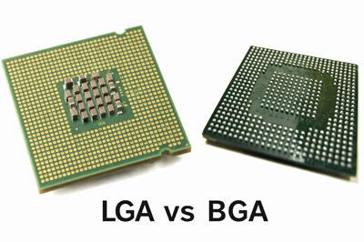
Figure 1. LGA vs BGA Overview
What is LGA (Land Grid Array)?
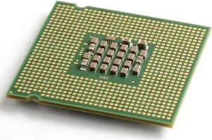
Figure 2. LGA Package
LGA (Land Grid Array) is a type of IC package where flat conductive pads, called lands, are located on the bottom of the component instead of pins or solder balls. These lands make contact with spring-loaded pins in a socket on the PCB, creating an electrical connection without permanent soldering. This design is widely used in CPUs and high-performance processors because it allows easy installation and replacement. The package itself does not contain solder elements, so the final connection is defined by the socket interface rather than the chip. This structure also simplifies visual inspection since the contacts are accessible on the surface.
What is BGA (Ball Grid Array)?
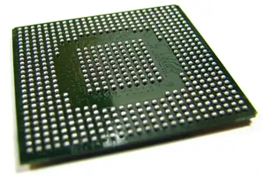
Figure 3. BGA Package
BGA (Ball Grid Array) is a surface-mount package that uses an array of small solder balls on the underside of the chip to form electrical connections. During assembly, these solder balls melt in a reflow process and bond directly to pads on the PCB, creating permanent joints. This packaging method enables a compact layout with a large number of interconnections in a small footprint. BGA packages are commonly used in high-density electronics such as smartphones, GPUs, and embedded systems. The solder balls also help distribute mechanical stress across the package during operation.
LGA vs BGA: Physical and Structural Differences
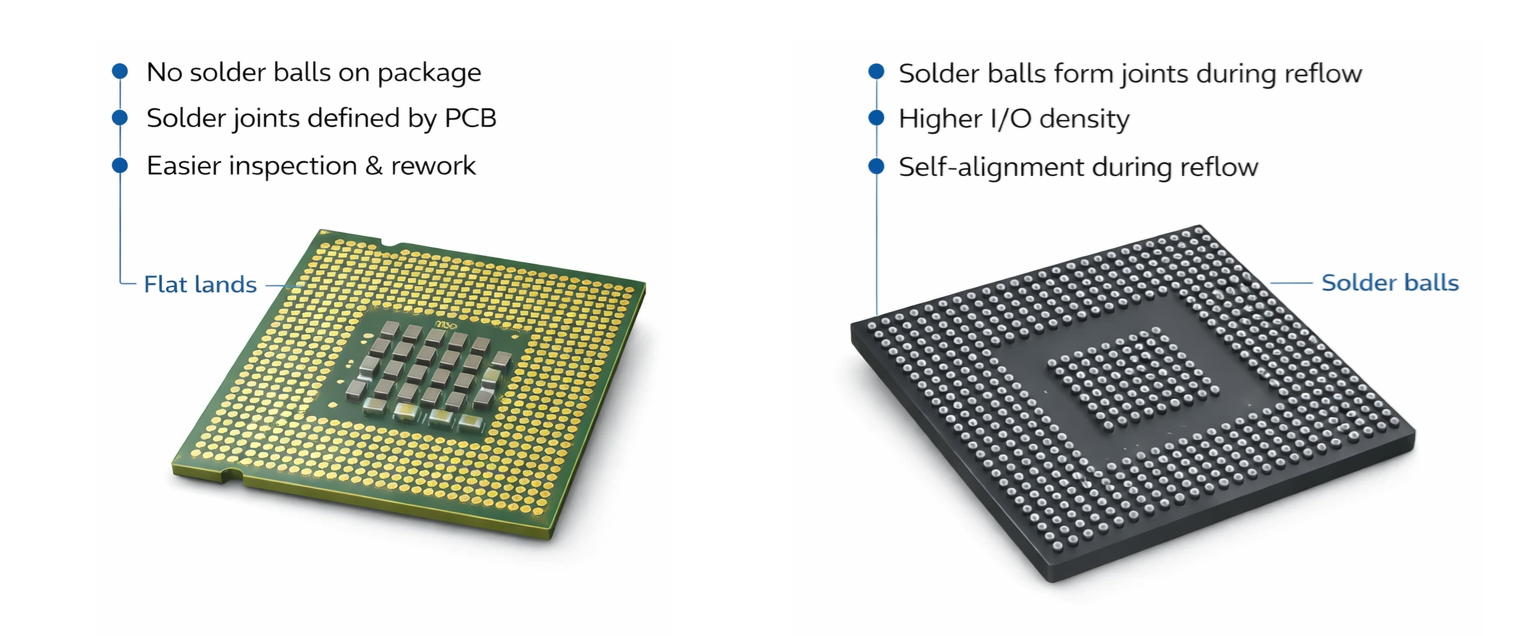
Figure 4. Structural Comparison
LGA packages use flat metallic lands arranged in a grid on the underside of the chip, which align with corresponding pins in a socket. These packages require a mechanical retention system, such as a socket and locking mechanism, to maintain reliable contact pressure. The absence of solder balls means the chip itself does not directly bond to the PCB, making it removable and reusable. The layout is defined by exposed contact pads that are clearly visible and accessible for inspection. In contrast, the mounting method depends on precise alignment within the socket rather than solder attachment. As seen in the figure, the flat and uniform pad surface distinguishes LGA from other package types.
BGA packages, on the other hand, feature an array of solder balls that act as both electrical connections and mechanical anchors. These solder balls are pre-attached to the package and melt during the reflow process to form permanent joints with the PCB. Unlike LGA, BGA components are directly mounted onto the board without a socket, making them non-removable without specialized rework equipment. The connections are hidden beneath the package, which makes visual inspection more challenging. The grid of solder balls also allows for tighter spacing and higher pin counts within the same footprint. As shown in the figure, the raised spherical contacts clearly differentiate BGA’s structure from the flat lands of LGA.
LGA vs BGA: Thermal and Electrical Performance
|
Performance
Aspect |
LGA (Land Grid
Array) |
BGA (Ball Grid
Array) |
|
Thermal
Dissipation |
Heat transfer
depends on socket contact and heatsink efficiency; slightly less direct
thermal path |
Direct solder
connection to PCB improves heat conduction and spreading efficiency |
|
Thermal
Resistance (θJA) |
Typically higher
due to interface layers between package and PCB |
Lower thermal
resistance due to direct attachment and better heat flow path |
|
Heat
Distribution Uniformity |
May have uneven
heat transfer depending on contact pressure distribution |
More uniform
heat distribution across solder joints and PCB |
|
Signal Integrity |
Slightly longer
signal path through socket may introduce impedance variation |
Short, direct
connections reduce signal loss and improve integrity |
|
Parasitic
Inductance |
Higher due to
socket pins and contact interface |
Lower due to
compact solder ball connections |
|
Electrical
Resistance |
Varies depending
on contact pressure and cleanliness of socket pins |
Low and stable
due to permanent metallurgical solder joints |
|
Power Delivery
Efficiency |
Good but
dependent on socket quality and pin contact consistency |
More efficient
due to low impedance paths and stable connections |
|
High-Frequency
Performance |
May experience
minor signal degradation at very high frequencies |
Better suited
for RF and high-speed designs due to minimal signal path length |
|
Electromagnetic
Performance |
Slightly higher
EMI risk due to longer interconnect paths |
Lower EMI due to
compact layout and shorter electrical loops |
|
Reliability
Under Load |
Performance may
vary over time due to wear or contamination in socket contacts |
Highly stable
performance over time due to fixed solder joints |
Advantages and Disadvantages of LGA
Advantages of LGA
• Allows easy installation and replacement without soldering, making it ideal for upgradeable systems.
• Simplifies inspection and maintenance since contacts are exposed and accessible.
• Reduces risk of package damage during handling because there are no fragile pins on the chip.
• Supports high pin counts while maintaining mechanical reliability through socket design.
Disadvantages of LGA
• Requires a socket, increasing overall system cost and board complexity.
• Contact reliability depends on consistent pressure and socket condition.
• Larger mechanical footprint compared to directly mounted packages.
• Susceptible to connection issues if contamination or misalignment occurs.
Advantages and Disadvantages of BGA
Advantages of BGA
• Enables very high I/O density in a compact footprint for modern electronics.
• Provides strong mechanical and electrical connections through solder joints.
• Improves electrical performance with shorter signal paths and lower inductance.
• Supports efficient thermal transfer through direct PCB attachment.
Disadvantages of BGA
• Difficult to inspect solder joints since they are hidden under the package.
• Requires specialized equipment for assembly and rework processes.
• Not easily replaceable once soldered onto the PCB.
• Manufacturing defects such as solder voids or bridging can be harder to detect.
How to Choose Between LGA and BGA Packages?
1. Define Serviceability Requirements
If your product requires easy upgrades or field replacement, LGA is typically more suitable because it allows non-permanent installation. This is especially important in systems like desktop computers or servers where components may need to be swapped. BGA, by contrast, is intended for permanent mounting and is not designed for frequent replacement. Consider how often maintenance or upgrades will occur over the product lifecycle. Selecting based on serviceability helps reduce long-term operational costs and downtime.
2. Evaluate Size and Space Constraints
For compact devices such as smartphones or embedded systems, BGA is often preferred due to its smaller footprint and higher density. LGA requires additional space for sockets and mechanical retention systems, which can increase board size. In space-constrained designs, minimizing footprint is good for overall product form factor. BGA enables tighter layouts and more efficient use of PCB area. This step ensures your package choice aligns with physical design limitations.
3. Consider Manufacturing Capabilities
Your available assembly process plays a major role in package selection. BGA requires controlled reflow soldering and inspection tools such as X-ray systems, which may not be available in all manufacturing setups. LGA, on the other hand, simplifies assembly by using sockets instead of soldering. Evaluate whether your production line can support the complexity of BGA assembly. Matching the package type with manufacturing capability avoids production risks.
4. Analyze Performance Requirements
High-speed and high-frequency applications often benefit from BGA due to shorter electrical paths and better signal integrity. LGA can still support high-performance applications but depends on socket quality and design. If your application involves demanding electrical performance, the package choice becomes important. Consider factors such as signal speed, noise, and power delivery stability. This ensures optimal performance for your specific use case.
5. Assess Cost Constraints
Budget considerations include both component and system-level costs. LGA may increase cost due to sockets and mechanical parts, while BGA can reduce board complexity but increase manufacturing expenses. The total cost should include assembly, testing, and potential rework. Evaluate the trade-offs between upfront and long-term costs. Choosing the right balance helps maintain profitability and scalability.
6. Determine Reliability Needs
For applications exposed to vibration, thermal cycling, or harsh environments, BGA often provides stronger mechanical stability due to soldered connections. LGA relies on mechanical pressure, which may be less robust under extreme conditions. Reliability requirements vary depending on the industry, such as automotive or industrial electronics. Consider environmental stress factors when selecting the package. This step ensures long-term durability and product reliability.
Applications of LGA and BGA Packages
Examples of LGA Components
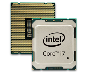
Figure 5. LGA Component Examples
• Desktop and Server CPUs - Many processors, such as Intel Core and Xeon series, use LGA packaging for socket-based installation. This allows to upgrade or replace CPUs without soldering. The design supports high pin counts required for complex processing tasks. It is widely used in personal computers and data centers.
• Network Interface Controllers - Certain Ethernet controllers adopt LGA packages to allow modular integration on motherboards. This helps simplify maintenance and replacement in networking hardware. The package supports stable electrical connections for high-speed data transfer. It is commonly found in enterprise networking equipment.
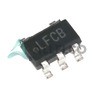
• Power Management ICs - Some power control devices use LGA for reliable contact and thermal performance. The flat pad design ensures consistent connection with the PCB or socket. These components are used in voltage regulation and power distribution systems. Their design supports efficient system-level integration.
• RF Modules - LGA is used in certain RF modules where compact size and reliable contact are required. The package supports high-frequency signal handling with stable connections. It is often used in communication devices and wireless systems. The structure allows easy integration into modular designs.
• Embedded Processors - Some embedded computing modules use LGA packaging for flexibility in industrial systems. This allows easier upgrades and maintenance in long-life applications. The package supports stable operation in controlled environments. It is commonly used in automation and control systems.
Examples of BGA Components
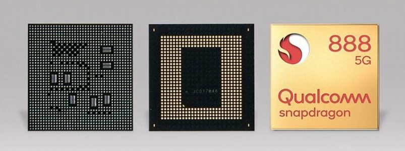
Figure 6. BGA Component Examples
• Graphics Processing Units (GPUs) - GPUs commonly use BGA packaging to support high pin density and fast data transfer. The compact design allows integration into graphics cards and laptops. Soldered connections improve performance and reliability under heavy workloads. This package is important for modern high-performance graphics systems.
• Mobile SoC Processors - Smartphone processors, such as those in Snapdragon series, rely on BGA for compact and efficient design. The package supports high integration of CPU, GPU, and connectivity features. It enables slim device profiles and high processing power. This makes it ideal for mobile and portable electronics.
• Field-Programmable Gate Arrays (FPGAs) - FPGAs often use BGA packages to accommodate large numbers of I/O connections. The design supports complex logic operations and high-speed communication. These components are used in telecommunications, AI, and data processing systems. The package ensures stable performance in demanding applications.
• Memory Chips (DRAM/Flash) - Many memory devices use BGA packaging for high-density stacking and efficient PCB layout. The small footprint allows multiple chips to be placed close together. This improves system performance and reduces latency. It is widely used in consumer electronics and computing systems.
• Chipsets and Controllers - Motherboard chipsets and embedded controllers frequently use BGA for permanent and reliable connections. The package supports complex functionality in a compact space. It is commonly used in laptops, tablets, and embedded systems. The design ensures long-term stability and performance.
Conclusion
LGA and BGA differ primarily in how they connect to the PCB, with LGA using socket-based contacts and BGA relying on soldered joints. LGA offers easier replacement and inspection, while BGA provides higher density, better electrical performance, and stronger mechanical stability. Each package has trade-offs in cost, manufacturability, and reliability depending on the application. Selecting the right option depends on balancing serviceability, space constraints, performance needs, and production capabilities.
About us
ALLELCO LIMITED
Read more
Quick inquiry
Please send an inquiry, we will respond immediately.
Frequently Asked Questions [FAQ]
1. Why do CPUs use LGA instead of BGA?
CPUs use LGA to allow easy installation, upgrades, and replacement without soldering, which is important for desktop and server systems.
2. Can BGA components be repaired or replaced?
Yes, but it requires specialized rework equipment like hot air stations and X-ray inspection, making it complex and costly.
3. Is LGA better for prototyping than BGA?
Yes, LGA is more suitable for prototyping because it allows repeated insertion and removal without damaging the PCB.
4. Does BGA have better signal integrity than LGA?
Yes, BGA typically offers better signal integrity due to shorter electrical paths and reduced inductance.
5. What tools are needed to assemble BGA packages?
BGA assembly requires reflow ovens, precise temperature control, solder paste, and often X-ray inspection systems.

Latch vs Flip-Flop: Comparison Guide for Digital Electronics
on April 2th
Through Hole in PCB Design Guidelines for Beginners
on April 1th
Popular Posts
-

Complex Instruction Set Computers: How They Changed Computing?
on April 17th 147721
-

USB-C Pinout and Features
on April 17th 111797
-

Using Xilinx Unified Simulation Primitives: A Comprehensive Guide to FPGA Design and Simulation
on April 17th 111330
-

Power Supply Voltages in Electronics: Meaning of VCC, VDD, VEE, VSS, and GND
on April 17th 83660
-

RJ45 Connector Guide: Pinout, Wiring, Cable Types, and Uses
on January 1th 79390
-

The Ultimate Guide to Wire Color Codes in Modern Electrical Systems
The way our electrical systems use colors isn’t just for looks. Each wire color now indicates a specific function, making it easier to identify and handle electrical components correctly during ins...on January 1th 66811
-

Quality (Q) Factor: Equations and Applications
The quality factor, or 'Q', is important when checking how well inductors and resonators work in electronic systems that use radio frequencies (RF). 'Q' measures how well a circuit minimizes energy...on January 1th 62968
-

Purge Valve Guide: Function, Symptoms, Testing, and Replacement for Optimal Engine Performance
The purge valve is a key part of a car’s system that helps keep the air clean by managing fuel vapors before they can escape into the atmosphere. This not only helps the environment by reducing pol...on January 1th 62870
-

Achieving Peak Performance with the Maximum Power Transfer Theorem
The Maximum Power Transfer Theorem explains how energy from a source, such as a battery or generator, flows to a connected load. It shows the exact condition where the load receives the most power....on January 1th 54051
-

A23 Battery Specifications and Compatibility
The A23 battery is a small, cylinder-shaped battery with high voltage. Also called 23A, 23AE, or MN21, it runs at 12 volts and much higher than AA or AAA batteries. Its special design make...on January 1th 52032
HOT Part Number
-

JANTX1N965B-1
MACOM Technology Solutions
DIODE ZENER 15V DO35
MC908AZ32ACFU
NXP USA Inc.
IC MCU 8BIT 32KB FLASH 64QFP
22-28-6080
Molex
KK 100 HDR ASSY RA BKWY 08 CKT T
P6KE18A-T
Diodes Incorporated
TVS DIODE 15.3VWM 25.2VC DO15
UC3843BVDG
onsemi
IC REG CTRLR FLYBACK 14SOIC
TPS70919DBVR
Texas Instruments
IC REG LINEAR 1.9V 150MA SOT23-5
GRM1555C1H9R6DA01D
Murata Electronics
CAP CER 9.6PF 50V C0G/NP0 0402
M95640-DRDW3TP/K
STMicroelectronics
IC EEPROM 64KBIT SPI 8TSSOP
SZMMSZ4713T1G
onsemi
DIODE ZENER 30V 500MW SOD123
MC68040FE25A
NXP USA Inc.
IC MPU M680X0 25MHZ 184CQFP
VI-MU4-EQ
Vicor Corporation
FLATPACK AC/DC POWER SUPPLY 48V
ST72F321BJ9T6
STMicroelectronics
IC MCU 8BIT 60KB FLASH 44LQFP
MCP130T-485I/TT
Microchip Technology
IC SUPERVISOR 1 CHANNEL SOT23-3
0402YA330KAT2A
KYOCERA AVX
CAP CER 33PF 16V C0G/NP0 0402
RD47M-T1B-A
Renesas
RD47M-T1B-A - ZENER DIODES 200 M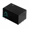
VSK-S1-12U
CUI Inc.
AC/DC CONVERTER 12V 1W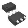
TMP303DDRLT
Texas Instruments
THERMOSTAT 125DEG PSH-PUL SOT563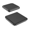
A40MX04-PLG68I
Microchip Technology
IC FPGA 57 I/O 68PLCC -
LP2992IM5X-1.8
Texas Instruments
IC REG LINEAR 1.8V 250MA SOT23-5
08051U390KAT2A
KYOCERA AVX
CAP CER 39PF 100V NP0 0805
74LVC573AQ20-13
Diodes Incorporated
IC OCTAL TRANSPAR LATCH 20QFN
GRM0336T1E9R7DD01D
Murata Electronics
CAP CER 9.7PF 25V T2H 0201
IXCP10M45S
IXYS
IC CURRENT REGULATOR TO220-3
06034D226MAT2A
AVX Corporation
CAP CER 22UF 4V X5R 0603
AD5262BRUZ200-RL7
Analog Devices Inc.
IC DGT POT 200KOHM 256TP 16TSSOP
MSCD165-18
Microsemi Corporation
DIODE MODULE 1.8KV 165A D2
XTR101BG
Texas Instruments
IC CURRENT TRANSMITTER 14CDIP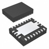
TPS40075RHLRG4
Texas Instruments
IC REG CTRLR BUCK 20VQFN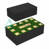
BGM15LA12E6327XTSA1
Infineon Technologies
IC AMP LTE 700MHZ-1GHZ 12ATSLP
SI7892BDP-T1-E3
Vishay Siliconix
MOSFET N-CH 30V 15A PPAK SO-8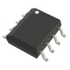
AD7894ARZ-2
Analog Devices Inc.
IC ADC 14BIT SAR 8SOIC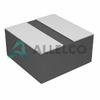
74438335010
Würth Elektronik
FIXED IND 1UH 2.7A 47 MOHM SMD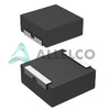
IHLP6767GZER100M11
Vishay Dale
FIXED IND 10UH 19A 9.33 MOHM SMD
0805YC103JAT2A
KYOCERA AVX
CAP CER 10000PF 16V X7R 0805
LTC7124IUDD#TRPBF
Analog Devices Inc.
IC REG BUCK ADJ 3.5A 24QFN
MAX4166ESA
Analog Devices Inc./Maxim Integrated
IC OPAMP GP 1 CIRCUIT 8SOIC -

COP8ACC728M9-XE
Texas Instruments
IC MCU 8BIT 4KB OTP 28SOIC
D80882
Intel
8088- MICROPROCESSOR, 8086/8088
BYWF29-200-E3/45
Vishay General Semiconductor - Diodes Division
DIODE GEN PURP 200V 8A ITO220AC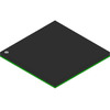
MPC853TZT66A
Freescale Semiconductor
RISC MPU, 32-BIT, 66.67MHZ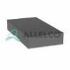
RK73H2HTTE5111F
KOA Speer Electronics, Inc.
RES 5.11K OHM 1% 3/4W 2010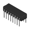
SN54LS257BJ
Texas Instruments
54LS257B QUADRUPLE 2-LINE TO 1-L
FAN8035L
onsemi
IC MOTOR CONTROL 48QFP
ATF-501P8-TR1
Broadcom Limited
FET RF 7V 2GHZ 8-LPCC
LQM18PN3R3MFRL
Murata Electronics
FIXED IND 3.3UH 700MA 438MOHM SM
GRM1885C1H821GA01D
Murata Electronics
CAP CER 820PF 50V C0G/NP0 0603
AT29C512-90TI
Microchip Technology
IC FLASH 512KBIT PARALLEL 32TSOP
MCC95-18IO8B
IXYS
MOD THYRISTOR DUAL 1800V TO240AA
TMP303EDRLR
Texas Instruments
THERMOSTAT 70DEG ACT HI SOT563-6
DAC7564IAPW
Texas Instruments
IC DAC 12BIT V-OUT 16TSSOP
BZX384-C6V8,115
NXP USA Inc.
DIODE ZENER 6.8V 300MW SOD323
LTC2472IMS#TRPBF
Analog Devices Inc.
IC ADC 16BIT SIGMA-DELTA 12MSOP
NLVVHCT50ADTR2G
onsemi
IC BUF NON-INVERT 5.5V 14TSSOP
IRFR210
Vishay Siliconix
MOSFET N-CH 200V 2.6A DPAK