LM3914: Pinout, Features, and How it Works?
The LM3914 integrated circuit stands out in the field of electronics for its ability to convert analog voltage levels into a visually intuitive LED display. This capability is good for applications that require clear and accurate voltage readings, such as in battery chargers and audio systems. By transforming analog signals into straightforward LED visuals, the LM3914 simplifies the development of display features in electronic devices. This article will delve into the pin configuration of the LM3914, explore its functionality, and discuss its wide-ranging applications, providing a comparative analysis with other ICs while highlighting specific advantages of using this versatile component.Catalog

Overview of the LM3914
The LM3914, an adaptable monolithic integrated circuit, excels in transforming varying voltage levels into a vibrant visual LED representation. It can skillfully manage up to 10 LEDs and operates in two distinct modes: dot mode, which lights one LED at a time, and bar mode, which activates all LEDs up to a specific voltage level. These modes can be switched with ease via a simple pin configuration, reflecting the IC's flexibility.
The ease of switching between dot and bar modes using just one pin enhances the LM3914's versatility for diverse applications. In practical scenarios, dot mode conserves energy by reducing active LEDs at any moment, which is a desirable trait in portable or energy-sensitive devices. On the other hand, bar mode provides an immediate, comprehensive display of the voltage level, serving well in contexts that demand rapid and intuitive data comprehension, such as audio visualization within a VU meter.
A notable characteristic of the LM3914 is its built-in capability to manage LED current without the need for external resistors, streamlining circuit design and minimizing components. This feature is advantageous in the creation of compact and efficient systems. The circuit’s low power requirements, paired with efficient LED current management, bolster its suitability for devices aiming for energy conservation. Using the LM3914 in low-power devices consistently meets energy-saving goals, proving its efficacy in conserving energy while maintaining strong performance.
LM3914 Pin Configuration
The LM3914 is available in two package types: a 20-pin PLCC and an 18-pin PDIP.
Pin Configuration of 20-pin PLCC

|
Pin Number |
Pin Name |
Description |
|
1 |
LED1 |
LED Driver Output 1 |
|
2 |
V+ |
Supply Voltage |
|
3 |
V- |
Ground |
|
4 |
Divider (Low End) |
Low Reference Voltage Input |
|
5 |
Signal Input |
Signal Input |
|
6 |
Divider (High End) |
High Reference Voltage Input |
|
7 |
NC |
Not Connected |
|
8 |
Reference Output |
Reference Voltage Output |
|
9 |
NC |
Not Connected |
|
10 |
Ref Adj |
Reference Voltage Adjust |
|
11 |
Mode Select |
Selects Dot or Bar Mode |
|
12 |
LED10 |
LED Driver Output 10 |
|
13 |
LED9 |
LED Driver Output 9 |
|
14 |
LED8 |
LED Driver Output 8 |
|
15 |
LED7 |
LED Driver Output 7 |
|
16 |
LED6 |
LED Driver Output 6 |
|
17 |
LED5 |
LED Driver Output 5 |
|
18 |
LED4 |
LED Driver Output 4 |
|
19 |
LED3 |
LED Driver Output 3 |
|
20 |
LED2 |
LED Driver Output 2 |
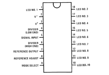
Pin Configuration of 18-pin PDIP
|
Pin Number |
Pin Name |
Description |
|
1 |
LED1 |
LED Driver Output 1 |
|
2 |
V+ |
Supply Voltage |
|
3 |
V- |
Ground |
|
4 |
Divider (Low End) |
Low Reference Voltage Input |
|
5 |
Signal Input |
Signal Input |
|
6 |
Divider (High End) |
High Reference Voltage Input |
|
7 |
Reference Output |
Reference Voltage Output |
|
8 |
Reference Adjust |
Reference Voltage Adjust |
|
9 |
Mode Select |
Selects Dot or Bar Mode |
|
10 |
LED10 |
LED Driver Output 10 |
|
11 |
LED9 |
LED Driver Output 9 |
|
12 |
LED8 |
LED Driver Output 8 |
|
13 |
LED7 |
LED Driver Output 7 |
|
14 |
LED6 |
LED Driver Output 6 |
|
15 |
LED5 |
LED Driver Output 5 |
|
16 |
LED4 |
LED Driver Output 4 |
|
17 |
LED3 |
LED Driver Output 3 |
|
18 |
LED2 |
LED Driver Output 2 |
LM3914 Features and Specifications
• Supports both bar and dot display modes.
• Adjustable voltage reference for precise LED activation thresholds.
• Programmable LED sink current: 2mA to 30mA.
• Controls up to 10 LEDs simultaneously.
• Drives up to 100 LEDs when multiple ICs are cascaded.
• Operates within a voltage range of 3V to 18V.
• Available in 18-pin DIP and PLCC packages.
Block Diagram of the LM3914

Alternatives to the LM3914
• LM3916
• CD4511
• MAX7219
• CD4054
Operational Complexity of the LM3914
The LM3914 IC is an analog-controlled LED driver designed to manage the brightness and activation of up to 10 individual LEDs. Its operation is based on the input analog voltage, which determines the specific LEDs that light up along the scale. Unlike setups that rely on microcontrollers, the LM3914 offers a simpler, more straightforward approach. It minimizes the need for additional components and eliminates the complexity of programming. The IC operates reliably within an analog voltage range of 3V to 18V, making it versatile for a variety of applications. Adjusting the LED current is simple, just connect a single resistor to pin 7 to regulate it as needed.
The LM3914 is especially versatile due to its ability to function in two display modes: bar mode and dot mode. In bar mode, multiple LEDs light up simultaneously to represent the input level, while in dot mode, only a single LED lights up at any given time. This flexibility makes the IC suitable for applications such as visual alarms, level indicators, or monitoring systems where a clear representation of changes in brightness is important. For larger-scale projects, the LM3914 can be easily expanded. By connecting multiple ICs in series, it’s possible to control up to 100 LEDs. This scalability broadens its use in complex systems requiring extended visual displays or indicators.
Utilization of the LM3914
Start by connecting the 10 LEDs. Each LED corresponds to a specific voltage level based on the input signal. You don’t need separate current-limiting resistors, as the IC has a built-in current limiter controlled through pin 7. Simply connect the cathode (negative side) of each LED to the appropriate output pin on the IC, while the anode (positive side) connects to the +5V supply. The IC’s output pins are designed to sink current, allowing this setup to work efficiently without additional components.
Next, provide power to the IC by connecting pins 2 and 3 to the power source. Make sure the supply voltage is at least 1.5V higher than the highest voltage the IC will monitor. For example, if the monitored voltage ranges from 0V to 5V, the supply voltage should be at least 6.5V. Proper power management ensures that the IC and the LEDs operate without issues.
Adjust the reference voltages to match the input signal range. Connect pin 4, which sets the low reference voltage, to 0V, and pin 6, which sets the high reference voltage, to 5V. These connections allow the IC to interpret input signals within the desired range. Then, connect the input analog signal to pin 5. This signal determines how many LEDs light up, as the IC compares the input voltage to its internal reference levels and activates the appropriate number of LEDs to indicate the voltage.
The LM3914 supports two display modes: bar mode and dot mode. In bar mode, where multiple LEDs light up to form a bar corresponding to the input voltage level, connect pin 9 to pin 3. For dot mode, where only one LED lights up to indicate the specific voltage level, leave pin 9 disconnected. Selecting the appropriate mode depends on how you want to visually represent the input signal.
Applications of the LM3914
Power Supply Monitors
When used in power supply monitoring, the LM3914 delivers precise visual feedback on voltage levels. It translates voltage variations into an easy-to-read LED display to quickly detect any fluctuations. This is especially use in applications where electronic components rely on a stable power supply to operate correctly. By ensuring consistent voltage levels, the LM3914 helps prevent hardware malfunctions, extend the lifespan of components, and maintain overall system reliability.
Automotive Dashboard Gauges
The LM3914 is a key component in modern automotive gauges, providing monitoring and display of vehicle information. It can be configured to track and show parameters such as fuel levels, engine temperature, or battery voltage. By converting sensor data into a clear visual format, it allows drivers to assess their vehicle’s condition at a glance. This ensures that important metrics are easily understood, enabling timely maintenance and promoting safer driving.
Audio Level Meters
The LM3914 is also widely used in audio level meters, providing a visual representation of sound volume levels. By activating a series of LEDs in response to audio signals, the circuit enables to monitor volume changes with precision. Depending on the application, the display can function in two modes: a bar display where multiple LEDs are lit simultaneously, or a dot display where only one LED is active at a time. These meters help fine-tune audio levels to avoid distortion, ensuring consistent sound quality in live performances or recordings.
Battery Level Indicators
The LM3914 plays a central role in designing battery level indicators, where it controls a sequence of LEDs to visually represent a battery’s charge status. Each LED lights up to indicate a specific range of charge levels, giving an immediate and intuitive sense of remaining battery life. This feature is valuable in portable devices, helping avoid unexpected power loss by offering a clear, display of battery status. By simplifying the process of gauging charge levels, it improves convenience and device reliability.
Pros and Cons
Pros
The LM3914’s elegant straightforwardness supports swift prototyping and integration across various applications. By reducing dependency on numerous external components, it cuts down on possible failure points, enhancing reliability. Its capability to run on one power supply increases its practicality in settings where dual supplies could complicate matters. When dealing with projects that prioritize efficient and vivid LED displays, the LM3914 excels by transforming analog signals into clear visual feedback, fostering satisfaction and operational fluidity.
Cons
However, it's important to acknowledge the LM3914's constraints. A noteworthy limitation is its fixed linear scale for LED displays, which might not suit every scenario, particularly those demanding logarithmic scaling to accurately depict data over extensive ranges. Having a nuanced understanding of the project's demands is needed before opting for the LM3914. While its direct approach serves well for straightforward implementations, complex or more dynamic environments might benefit from exploring other options that grant finer control over how the display behaves.
Comparison Between LM3914 and LM3915
Characteristics of LM3914 and LM3915
Devices such as the LM3914 and LM3915, crafted for visual representation of analog voltages, excel through their distinctive output types. The LM3914 converts input voltage into a linear display, making it apt for scenarios where straightforward voltage measurements are desired. On the flip side, the LM3915 produces a logarithmic output that finds its niche in managing audio signals, aligning well with the inherently logarithmic nature of auditory perception.
Applications
When selecting the suitable component for a specific task, reflection on the application's unique demands is important. For implementations like battery level indicators or other voltage monitoring systems, the linear scale of the LM3914 offers greater convenience. Its straightforwardness lends itself to an easily comprehensible display of voltage levels. In contrast, for audio-centric applications, the logarithmic display of the LM3915 can enhance the experience greatly. Given that audio signals often span a vast dynamism, a scale like that of the LM3915 which emulates the ear's non-linear perception of sound intensity, provides a richer interpretation and insight.
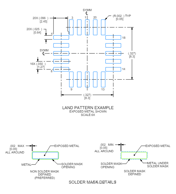
Package for LM3914
LM3914 Manufacturer Information
Texas Instruments stands as a pioneer in semiconductor production, embodying a commitment to superior quality with the LM3914. This product, renowned for its consistent performance, aligns closely with the precision demands of various applications. Their sophisticated manufacturing procedures ensure that each unit aligns with the highest expectations. Texas Instruments provides support that transcends the mere physical product, characterized by detailed datasheets accompanying the LM3914. These documents simplify the integration process into diverse electronic layouts, offering insights beyond standard specifications.
Conclusion
The LM3914 is a reliable and versatile IC designed for converting analog voltages into intuitive LED displays. Its simplicity, flexibility in dot and bar modes, and ability to drive up to 10 LEDs make it ideal for applications such as battery level indicators, power monitors, and audio meters. With its efficient design and adaptability, the LM3914 continues to be a preferred choice for creating clear and effective visual voltage displays in a wide range of electronic systems.
About us
ALLELCO LIMITED
Read more
Quick inquiry
Please send an inquiry, we will respond immediately.
Frequently Asked Questions [FAQ]
1. What is the function of the LM3914?
The LM3914 is a versatile integrated circuit adept at converting analog voltage levels into a dynamic visual display with 10 LEDs. This ability positions it as an integral part of systems that visualize linear analog data. It simplifies the journey from raw data to intuitive interpretation, often found in applications such as battery level indicators and audio signal meters. Its role is particularly valuable where visual feedback helps users effortlessly grasp variations in voltage levels.
2. Is the LM3914 IC considered analog or digital?
The LM3914 essentially operates as an analog display IC. Although its LED output presents a digital visual, it processes inputs through a linear analog method. This blend allows for the conversion of complex analog signals into accessible visual formats, maintaining the integrity of original data while enhancing user interaction. By converting analog information into straightforward visuals, it bridges the technical and user-friendly worlds.
3. What is the maximum current capacity for the LM3914?
The LM3914 handles a current of up to 2.5mA. This relatively low current draw highlights its efficiency in power usage, making it suitable for inclusion in portable and battery-driven devices. In many design plans, keeping power consumption low is beneficial, particularly when focusing on sustainability and efficiency. This capability helps developers create solutions that respect both environmental constraints and functional needs.
4. How does the LM3914 differ from the LM3916?
The LM3914 and LM3916 ICs primarily differ in how they transform outputs. The LM3914 features a linear output scale, fitting for applications where consistent voltage portrayal is needed. On the other hand, the LM3916 uses a logarithmic VU (volume unit) scale. This logarithmic trait is particularly insightful in audio scenarios where sound intensity perceived by humans isn't linear. Recognizing these differences aids in selecting the appropriate component, ensuring project needs are met with both technical precision and user satisfaction.

Everything You Need to Know About the 74HC266 and 74LS266 XNOR Gates
on December 4th

Understanding 74HC136 and 74LS136 XOR Gates in the 7400 Logic Series
on December 3th
Popular Posts
-

Complex Instruction Set Computers: How They Changed Computing?
on April 18th 147751
-

USB-C Pinout and Features
on April 18th 111923
-

Using Xilinx Unified Simulation Primitives: A Comprehensive Guide to FPGA Design and Simulation
on April 18th 111349
-

Power Supply Voltages in Electronics: Meaning of VCC, VDD, VEE, VSS, and GND
on April 18th 83714
-

RJ45 Connector Guide: Pinout, Wiring, Cable Types, and Uses
on January 1th 79502
-

The Ultimate Guide to Wire Color Codes in Modern Electrical Systems
The way our electrical systems use colors isn’t just for looks. Each wire color now indicates a specific function, making it easier to identify and handle electrical components correctly during ins...on January 1th 66872
-

Quality (Q) Factor: Equations and Applications
The quality factor, or 'Q', is important when checking how well inductors and resonators work in electronic systems that use radio frequencies (RF). 'Q' measures how well a circuit minimizes energy...on January 1th 63005
-

Purge Valve Guide: Function, Symptoms, Testing, and Replacement for Optimal Engine Performance
The purge valve is a key part of a car’s system that helps keep the air clean by managing fuel vapors before they can escape into the atmosphere. This not only helps the environment by reducing pol...on January 1th 62955
-

Achieving Peak Performance with the Maximum Power Transfer Theorem
The Maximum Power Transfer Theorem explains how energy from a source, such as a battery or generator, flows to a connected load. It shows the exact condition where the load receives the most power....on January 1th 54078
-

A23 Battery Specifications and Compatibility
The A23 battery is a small, cylinder-shaped battery with high voltage. Also called 23A, 23AE, or MN21, it runs at 12 volts and much higher than AA or AAA batteries. Its special design make...on January 1th 52092
HOT Part Number
-

AP2553FDC-7
Diodes Incorporated
IC PWR SWITCH P-CHANNEL 1:1 6DFN
REG1117FA-5.0/500
Texas Instruments
IC REG LIN 5V 1A DDPAK/TO263-3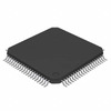
DSPIC33CH64MP508-I/PT
Microchip Technology
IC MCU 16BIT 88KB FLASH 80TQFP
NVTFS5826NLWFTWG
onsemi
MOSFET N-CH 60V 7.6A 8WDFN
CL03C180JA3ANNC
Samsung Electro-Mechanics
CAP CER 18PF 25V C0G/NP0 0201
C1608X8R1H103M080AE
TDK Corporation
CAP CER 10000PF 50V X8R 0603
LTC1682IMS8-5#PBF
Analog Devices Inc.
IC REG CHARGE PUMP 5V 50MA 8MSOP
PXAS30KBA
Rochester Electronics, LLC
IC MCU 16BIT ROMLESS 68PLCC
C3216Y5V1C106Z
TDK Corporation
CAP CER 10UF 16V Y5V 1206
ADA4610-1ARZ-R7
Analog Devices Inc.
IC OPAMP JFET 1 CIRCUIT 8SOIC
BYM11-200-E3/97
Vishay General Semiconductor - Diodes Division
DIODE GEN PURP 200V 1A DO213AB
GRM2167U1H560JZ01D
Murata Electronics
CAP CER 56PF 50V U2J 0805
TOP258GN-TL
Power Integrations
IC OFFLINE SWITCH FLYBACK 8SMD
STM8S207RBT3
STMicroelectronics
IC MCU 8BIT 128KB FLASH 64LQFP
XC6701B502MR-G
Torex Semiconductor Ltd
IC REG LINEAR 5V 150MA SOT25
08053G104ZAT2A
AVX Corporation
CAP CER 0.1UF 25V Y5V 0805
BZM55B13-TR
Vishay General Semiconductor - Diodes Division
DIODE ZENER 13V 500MW MICROMELF
MCH5809-TL-E
onsemi
NCH+SBD 2.5V DRIVE SERIES -

BZD17C3V6P-E3-08
Vishay General Semiconductor - Diodes Division
DIODE ZENER 3.6V 800MW DO219AB
DSRHD06-13
Diodes Incorporated
BRIDGE RECT 1P 600V 1A T-MINIDIP
BCX54-16E6327
Infineon Technologies
SMALL SIGNAL BIPOLAR TRANSISTOR
AD9961BCPZ
Analog Devices Inc.
IC BROADBAND FRONT-END 72LFCSP
AT80C51RD2-RLRUM
Microchip Technology
IC MCU 8BIT ROMLESS 44VQFP
PHK31NQ03LT,518
Nexperia USA Inc.
MOSFET N-CH 30V 30.4A 8SO
1469002-1
TE Connectivity AMP Connectors
CONN HDR HIGH SPEED 120POS PCB
S5JHE3_A/I
Vishay General Semiconductor - Diodes Division
DIODE GEN PURP 600V 5A DO214AB
SCAN90004TVS
Texas Instruments
IC REDRIVER LVDS 4CH 48TQFP
CD4025BCN
onsemi
IC GATE NOR 3CH 3-INP 14DIP
2225HC332KAT1A
KYOCERA AVX
CAP CER 3300PF 3KV X7R 2225
MN63Y1208-E1
Panasonic Electronic Components
IC RFID READR/TRAN 13.56MZ 16QFN
06035C112JAT2A
KYOCERA AVX
CAP CER 1100PF 50V X7R 0603
LFE3-95EA-8LFN672I
Lattice Semiconductor Corporation
IC FPGA 380 I/O 672FPBGA
XBS053V13R-G
Torex Semiconductor Ltd
DIODE SCHOTTKY 20V 500MA SOD323A
GRM0335C2A6R5CA01J
Murata Electronics
CAP CER 6.5PF 100V C0G/NP0 0201
STW36N55M5
STMicroelectronics
MOSFET N-CH 550V 33A TO247
C1608C0G2A090D080AA
TDK Corporation
CAP CER 9PF 100V C0G 0603 -
GRM1886P1H4R8CZ01D
Murata Electronics
CAP CER 4.8PF 50V P2H 0603
M29W128FL70N6E
Micron Technology Inc.
IC FLASH 128MBIT PARALLEL 56TSOP
70MT100KB
Vishay General Semiconductor - Diodes Division
BRIDGE RECT 3PHASE 1KV 70A MTK
ADXL344ACCZ-RL7
Analog Devices Inc.
ACCEL 2-16G I2C/SPI 16LGA
BZX84C39-HE3-08
Vishay General Semiconductor - Diodes Division
DIODE ZENER 39V 300MW SOT23-3
1735447-7
TE Connectivity AMP Connectors
CONN RCPT HSG 7POS 2.00MM
1808AA150JAT1A
KYOCERA AVX
CAP CER 15PF 1KV NP0 1808
Z84C4106PEC
Zilog
IC INTERFACE SPECIALIZED 40DIP
GRM1555C1H7R4WZ01D
Murata Electronics
CAP CER 7.4PF 50V C0G/NP0 0402
BDCN-20-13+
Mini-Circuits
RF DIR COUPLER 360MHZ-1GHZ 6SMD
MCC19-14IO1B
IXYS
MOD THYRISTOR DUAL 1400V TO240AA
OP467GPZ
Analog Devices Inc.
IC OPAMP GP 4 CIRCUIT 14DIP
LA4636-E
Sanyo
11 WATT 2-CHANNEL BTL AF POWER A
P6KE82A-T
Diodes Incorporated
TVS DIODE 70.1VWM 113VC DO15
NCV7608DWR2G
onsemi
IC HALF BRIDGE DRIVER 28SOIC
TLJA227M004R1100
KYOCERA AVX
CAP TANT 220UF 20% 4V 1206
TUSB2136PM
Texas Instruments
IC USB HUB I/O CONTROL 64-LQFP
HUFA75637P3
onsemi
MOSFET N-CH 100V 44A TO220-3