Overview of Carbon Film Resistors
You often see carbon film resistors on circuit boards, but it’s not always clear what makes them different or how to use them properly. This article walks you through what a carbon film resistor is, how it works, and why it’s commonly chosen in everyday electronics. You’ll learn how resistance, tolerance, power rating, and temperature behavior affect performance, along with where these resistors are used and how to pick the right one for a circuit. Everything is explained in plain language, so you can follow along even without a technical background.Catalog
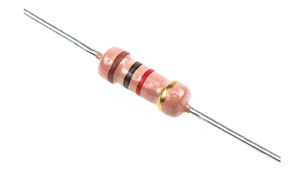
Figure 1. Carbon Film Resistor
What Is a Carbon Film Resistor
A carbon film resistor is a fixed resistor used in electronic circuits to control the flow of electric current and manage voltage levels. It is classified as a passive electronic component, meaning it does not generate energy or amplify signals, but instead provides a stable resistance that supports normal circuit operation. The resistance value is set during manufacturing and remains constant under standard operating conditions, which places carbon film resistors firmly in the fixed resistor category.
Because their resistance cannot be adjusted after production, carbon film resistors are used in circuits that require predictable and consistent electrical behavior. They are commonly applied to limit current, reduce voltage, and help establish defined electrical conditions within a circuit. This combination of stable performance and straightforward function makes carbon film resistors a practical choice for many general electronic applications.
Working Principle and Construction
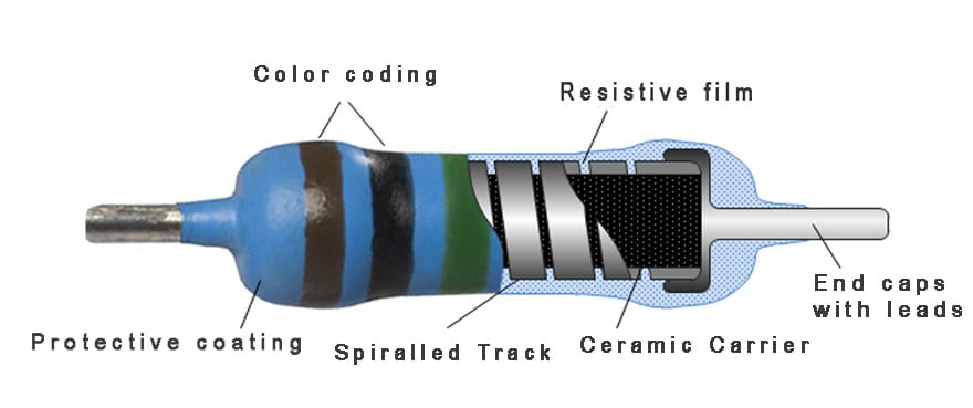
Figure 2. Carbon Film Resistor Structure
A carbon film resistor operates by restricting the flow of electric current through a thin carbon layer applied to an insulating base. When a voltage is applied across the terminals, current enters through one lead, travels along the carbon film, and exits through the other, with the carbon material providing controlled opposition that produces a defined resistance value.
That resistance is set by the length and thickness of the carbon path. A longer path increases resistance because the current must travel farther, while a shorter path lowers it, and a thinner carbon layer offers greater resistance than a thicker one. To achieve accurate resistance values without increasing physical size, the carbon layer is commonly formed into a spiral path, which extends the effective current path within a compact structure.
The physical structure is built around a ceramic core that provides mechanical support and electrical insulation, with a carbon film coating surrounding it as the resistive element. Metal end caps are attached to each end of the carbon layer to ensure reliable electrical contact, and metal leads extend from these caps for connection to a circuit. The entire assembly is sealed with a protective outer coating, which helps maintain stable operation during normal use.
Electrical Characteristics of Carbon Film Resistors
Carbon film resistors are defined by properties such as resistance value, tolerance, power rating, and temperature behavior, which determine how they perform in a circuit.
Resistance Range
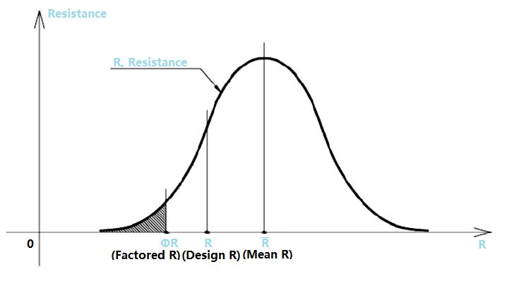
Figure 3. Resistance Value Distribution
The resistance range of carbon film resistors covers a wide span of values, from low resistance to high resistance levels. This range represents the nominal values that manufacturers design and produce. As illustrated by the resistance distribution curve, the rated resistance is centered around a design value, with actual manufactured values clustering closely around this point. This shows that resistance values are not random but intentionally controlled during production to remain near the specified rating.
The color band chart further supports this concept by showing how different resistance values are represented using standardized color codes. Each combination of bands corresponds to a specific resistance within the available range, allowing the value to be identified directly on the resistor body.
Tolerance
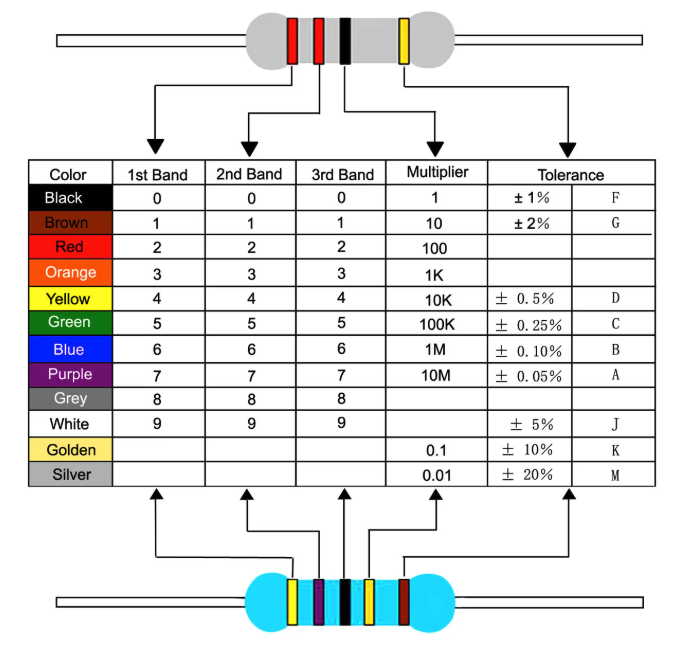
Figure 4. Resistor Color Code and Tolerance
Tolerance defines the allowable variation around the nominal resistance value. The bell-shaped curve image visually represents this concept by showing how most resistors fall near the center value, while fewer parts appear toward the limits. This illustrates that tolerance is a controlled range rather than an error.
In practice, tolerance is indicated by a dedicated color band on the resistor, as shown in the color code reference. This band communicates how much deviation from the nominal value is acceptable. Tighter tolerance means less variation, while wider tolerance allows greater deviation without affecting normal circuit operation.
Power Rating
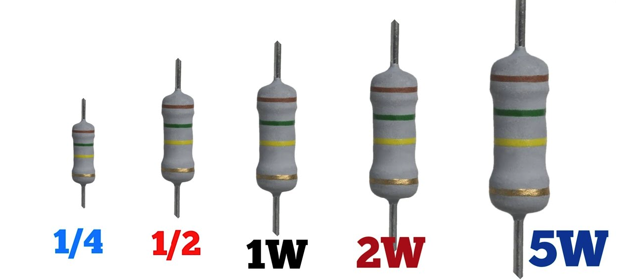
Figure 5. Carbon Film Resistor Power Ratings
The power rating describes how much electrical power a carbon film resistor can safely dissipate as heat. The size comparison image clearly demonstrates this relationship by showing resistors with increasing physical size labeled with higher power ratings. Larger resistors are able to dissipate more heat due to their greater surface area and material volume.
Unlike resistance and tolerance, power rating is not indicated by color bands. Instead, it is determined by the resistor’s physical dimensions and construction. Selecting the correct power rating helps prevent overheating and ensures stable performance during operation.
Temperature Behavior
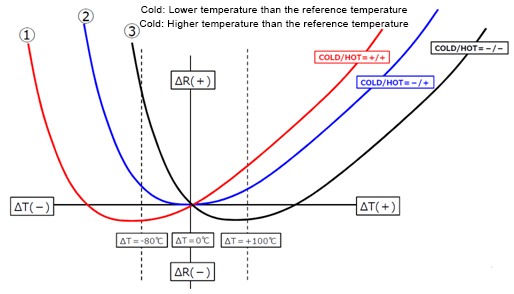
Figure 6. Resistance Change With Temperature
Temperature behavior describes how resistance changes as operating temperature rises or falls. The temperature response graph shows how resistance shifts relative to a reference temperature, with resistance increasing or decreasing depending on material characteristics. This visual representation helps clarify that resistance is not perfectly constant across all temperatures.
This behavior is summarized by the temperature coefficient, which indicates the direction and degree of resistance change with temperature variation. While carbon film resistors exhibit predictable temperature response, small resistance shifts are normal and acceptable for general electronic applications.
Advantages and Disadvantages
| Advantages | Limitations |
| Stable resistance under normal operating conditions | Lower accuracy compared to metal film resistors |
| Lower electrical noise than carbon composition resistors | Resistance value can drift slightly with temperature |
| Wider tolerance options than precision resistor types | Not ideal for high-precision or measurement circuits |
| Simple and proven construction | Limited long-term stability compared to metal film |
| Wide range of resistance values available | Less consistent performance in tightly regulated designs |
| Suitable for high-voltage applications | Performance affected by humidity if coating degrades |
| Good performance at elevated temperatures | Not suited for very low-noise or high-frequency precision applications |
| Cost-effective for general-purpose use |
|
| Compact size for many power ratings |
|
Applications of Carbon Film Resistors
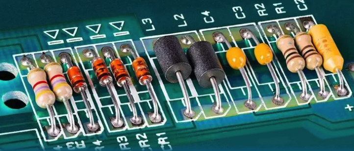
Figure 7. Carbon Film Resistors on Printed Circuit Board
Carbon film resistors are commonly used in general electronic circuits where consistent resistance is required for normal operation. On printed circuit boards like the one shown, they are installed alongside other passive components to control current flow and establish voltage levels within signal paths and basic control sections. Their predictable behavior makes them suitable for consumer electronics, educational projects, and routine circuit assemblies.
They are also applied in high-voltage circuits, where components must tolerate increased electrical stress without breakdown. In these designs, carbon film resistors are used in voltage divider networks, power supply sections, and protection paths to help manage voltage safely and reliably. Their construction supports stable performance under higher voltage conditions.
In high-temperature environments, carbon film resistors are selected when moderate resistance stability is acceptable. The ceramic core and carbon film structure allow operation at elevated temperatures commonly found in power electronics and industrial equipment. These characteristics make carbon film resistors a practical option for circuits exposed to heat where precise resistance control is not critical.
How to Choose a Carbon Film Resistor
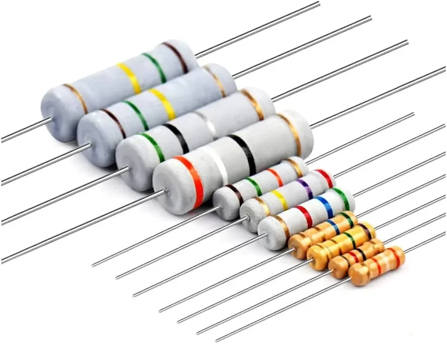
Figure 8. Selection of Carbon Film Resistors
Choosing a carbon film resistor begins with selecting the required resistance value, which is defined by the circuit design and determines how current or voltage is controlled. The chosen value should closely match the intended requirement to ensure the circuit operates as expected.
The next factor is tolerance, which indicates how much the actual resistance may vary from the rated value. Circuits that depend on stable electrical levels benefit from tighter tolerance ratings, while general-purpose designs can operate reliably with wider tolerance ranges.
The power rating should be selected to safely handle the amount of heat generated during operation. Choosing a resistor with a power rating higher than the expected dissipation helps avoid overheating and supports long-term reliability.
Finally, the operating temperature range should be considered when the resistor is used near heat sources or in warm environments. Keeping operation within the specified temperature limits helps maintain stable resistance and consistent performance.
Conclusion
Carbon film resistors are widely used because they offer stable resistance and predictable behavior in many electronic circuits. By understanding how they work, how they are built, and what their electrical characteristics mean, you can better judge when they fit your needs. Their advantages make them suitable for general electronics, while their limitations help define where other resistor types may be a better option. Knowing how resistance, tolerance, power rating, and temperature behavior affect performance makes selection easier. When chosen correctly, carbon film resistors provide reliable operation in both simple projects and practical circuit designs.
About us
ALLELCO LIMITED
Read more
Quick inquiry
Please send an inquiry, we will respond immediately.
Frequently Asked Questions [FAQ]
1. What is a carbon film resistor used for?
Carbon film resistors are used to control current and voltage in electronic circuits, helping set operating conditions and protect components.
2. Are carbon film resistors adjustable?
No, carbon film resistors are fixed resistors, meaning their resistance value is set during manufacturing and cannot be adjusted.
3. How do you identify the resistance value of a carbon film resistor?
The resistance value is identified using color bands printed on the resistor body, which represent digits and a multiplier.
4. Can carbon film resistors handle high temperatures?
They can operate at moderately high temperatures, but their resistance may change slightly as temperature increases.
5. When should you avoid using carbon film resistors?
They are not ideal for circuits that require very high accuracy, tight tolerance, or extreme long-term stability.

What Makes the EP2S130F1020C3 FPGA Suitable for Complex Designs
on January 8th
Exploring the EPF10K30ATI144-3N FPGA Architecture and Specs
on January 6th
Popular Posts
-

Complex Instruction Set Computers: How They Changed Computing?
on April 18th 147754
-

USB-C Pinout and Features
on April 18th 111931
-

Using Xilinx Unified Simulation Primitives: A Comprehensive Guide to FPGA Design and Simulation
on April 18th 111349
-

Power Supply Voltages in Electronics: Meaning of VCC, VDD, VEE, VSS, and GND
on April 18th 83718
-

RJ45 Connector Guide: Pinout, Wiring, Cable Types, and Uses
on January 1th 79505
-

The Ultimate Guide to Wire Color Codes in Modern Electrical Systems
The way our electrical systems use colors isn’t just for looks. Each wire color now indicates a specific function, making it easier to identify and handle electrical components correctly during ins...on January 1th 66873
-

Quality (Q) Factor: Equations and Applications
The quality factor, or 'Q', is important when checking how well inductors and resonators work in electronic systems that use radio frequencies (RF). 'Q' measures how well a circuit minimizes energy...on January 1th 63010
-

Purge Valve Guide: Function, Symptoms, Testing, and Replacement for Optimal Engine Performance
The purge valve is a key part of a car’s system that helps keep the air clean by managing fuel vapors before they can escape into the atmosphere. This not only helps the environment by reducing pol...on January 1th 62960
-

Achieving Peak Performance with the Maximum Power Transfer Theorem
The Maximum Power Transfer Theorem explains how energy from a source, such as a battery or generator, flows to a connected load. It shows the exact condition where the load receives the most power....on January 1th 54080
-

A23 Battery Specifications and Compatibility
The A23 battery is a small, cylinder-shaped battery with high voltage. Also called 23A, 23AE, or MN21, it runs at 12 volts and much higher than AA or AAA batteries. Its special design make...on January 1th 52101
HOT Part Number
-

1N3341R
Solid State Inc.
DO5 50 WATT ZENER DIODES
MXL1016IS8-T
Analog Devices Inc./Maxim Integrated
IC COMPARATOR 1 W/LATCH 8SOIC
ISL8200MIRZ
Renesas Electronics America Inc
DC DC CONVERTER 0.6-6V
LTC2850HS8#PBF
Analog Devices Inc.
IC TRANSCEIVER HALF 1/1 8SOIC
STB6N60M2
STMicroelectronics
MOSFET N-CH 600V 4.5A D2PAK
LT3430EFE#TRPBF
Analog Devices Inc.
IC REG BUCK SEPIC ADJ 3A 16TSSOP
APX803L20-13SA-7
Diodes Incorporated
IC SUPERVISOR 1 CHANNEL SOT23
0429.200WRM
Littelfuse Inc.
FUSE BOARD MNT 200MA 125VAC/VDC
24C01C-I/P
Microchip Technology
IC EEPROM 1KBIT I2C 400KHZ 8DIP
LTC2297IUP#TRPBF
Analog Devices Inc.
IC ADC 14BIT PIPELINED 64QFN
08051C562JAT4A
KYOCERA AVX
CAP CER 5600PF 100V X7R 0805
BZT52B15
Diotec Semiconductor
DIODE ZENER 15V 500MW SOD123F
TPS2421-2DDAR
Texas Instruments
IC HOT SWAP CTRLR GP 8SOPWR
UCC28070PWRG4
Texas Instruments
IC PFC CONTROLLER CCM 20TSSOP
RT0402DRD0718RL
YAGEO
RES SMD 18 OHM 0.5% 1/16W 0402
BAT54ZFILM
STMicroelectronics
DIODE SCHOTTKY 40V 300MA SOD123
TLIN10283DRQ1
Texas Instruments
IC TRANSCEIVER 1/1 8SOIC
MC9S08LL64CLH
NXP USA Inc.
IC MCU 8BIT 64KB FLASH 64LQFP -
CD54ACT373F3A
Texas Instruments
OCTAL TRANSPARENT LATCHES WITH 3
MAX5391NATE+T
Analog Devices Inc./Maxim Integrated
IC DGT POT 100KOHM 256TAP 16TQFN
PI90LVB010WE
Diodes Incorporated
IC RECEIVER 0/4 8SOIC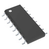
TB5T1D
Texas Instruments
IC TRANSCEIVER FULL 2/2 16SOIC
HSR412
onsemi
SSR RELAY SPST-NO 140MA 0-400V
IKW25N120T2FKSA1
Infineon Technologies
IGBT TRENCH 1200V 50A TO247-3
NCP502SQ30T1
onsemi
IC REG LINEAR 3V 80MA SC88A
SMAJ24CA
SMC Diode Solutions
TVS DIODE 24VWM 38.9VC SMA
C1005X6S1A334M050BC
TDK Corporation
CAP CER 0.33UF 10V X6S 0402
AD8221AR
Analog Devices Inc.
IC INST AMP 1 CIRCUIT 8SOIC
MPQ2171GJ-AEC1-Z
Monolithic Power Systems Inc.
AUTOMOTIVE GRADE. 5.5V, 1A, 2.6M
AD790JRZ-REEL7
Analog Devices Inc.
IC COMPARATOR 1 W/LATCH 8SOIC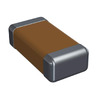
12061A270JA12A
KYOCERA AVX
CAP CER 27PF 100V NP0 1206
LT3694IFE#PBF
Analog Devices Inc.
IC REG TRIPLE BUCK/LNR 20TSSOP
DS2431Q+U
Analog Devices Inc./Maxim Integrated
IC EEPROM 1KBIT 1-WIRE 6TDFN
GRM1555C1H4R3BZ01D
Murata Electronics
CAP CER 4.3PF 50V C0G/NP0 0402
A40MX04-PL44
Microchip Technology
IC FPGA 34 I/O 44PLCC
12104D107KAT2A
KYOCERA AVX
CAP CER 100UF 4V X5R 1210 -

ADA4084-4ARUZ
Analog Devices Inc.
IC OPAMP GP 4 CIRCUIT 14TSSOP
LTC3704EMS#PBF
Analog Devices Inc.
IC REG CTRLR CUK 10MSOP
AONS66406
Alpha & Omega Semiconductor Inc.
N
AP7343-28W5-7
Diodes Incorporated
IC REG LINEAR 2.8V 300MA SOT25
74107PC
Texas Instruments
J-K FLIP-FLOP
04025A6R0DAT2A
KYOCERA AVX
CAP CER 6PF 50V NP0 0402
RT9193-33GB
Richtek USA Inc.
IC REG LINEAR 3.3V 300MA SOT23-5
VI-J51-EZ
Vicor Corporation
DC DC CONVERTER 12V 25W
MAX20075ATCA/V+
Analog Devices Inc./Maxim Integrated
IC REG BUCK PROG 600MA 12TDFN
GRM188R61E106MA73J
Murata Electronics
CAP CER 10UF 25V X5R 0603
PIC18C658-I/L
Microchip Technology
IC MCU 8BIT 32KB OTP 68PLCC
MPM3620GQV-P
Monolithic Power Systems Inc.
DC DC CONVERTER 0.8-18.48V
VLS201610ET-6R8M
TDK Corporation
FIXED IND 6.8UH 530MA 840MOHM SM
MHP-TAM15-9-72
Littelfuse Inc.
THERMOSTAT 72DEG C SPST-NC STRAP
PWB130A40
SanRex Corporation
THYRISTOR MODULE 400V 130A
BCM20704UA1KFFB1G
Cypress Semiconductor Corp
SINGLE-CHIP BLUETOOTH TRANSCEIVE
XC7Z035-L2FFG676I
AMD
IC SOC CORTEX-A9 800MHZ 676FCBGA
S-1132B18-M5T1G
ABLIC Inc.
IC REG LINEAR 1.8V 300MA SOT23-5