PIC18F4620 Microcontroller: Features, Pinouts, and Datasheet Guide
This article begins by exploring the PIC18F4620 microcontroller, discuss its balance between computational power and cost-efficiency. We'll examine the microcontroller’s capabilities in detail, such as its durability and energy efficiency. This method not only makes the information more relatable but also more useful for you, encouraging a deeper appreciation of the technology and motivating further exploration into the PIC18F4620's role in advancing microcontroller technology.Catalog

Overview of PIC18F4620
The PIC18F4620 microcontroller showcases a blend of computational efficiency and cost-effectiveness, leveraging its Enhanced Flash program memory for superior durability and an extended lifespan. This characteristic finds utility in applications requiring frequent memory rewrites, ensuring long-term reliability. The PIC18 series including the PIC18F2525, PIC18F2620, PIC18F4525, and PIC18F4620 models is crafted to fulfill the needs of high-performance and power-sensitive implementations.
Pinout of PIC18F4620
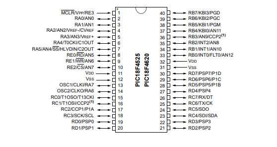
Pin Configuration
Power and Ground Pins
The power requirements for the PIC18F4620 range from 2V to 5.5V, catered through the VDD and VSS pins. VDD connects to the positive supply voltage. VSS is designated for ground.
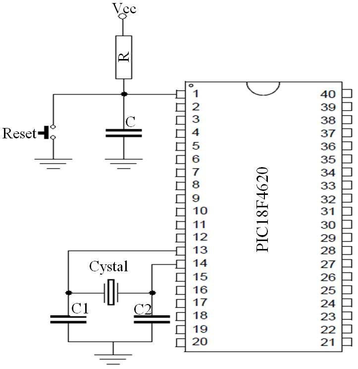
Placing appropriate decoupling capacitors, such as ceramic or tantalum types, near these pins helps in noise reduction and maintaining stable operation, stable power delivery underpins consistent microcontroller performance.
Oscillator Pins
The OSC1 and OSC2 pins are utilized for connecting external crystals or resonators, generating the clock signal needed for operation. The choice of clock source is use as it influences both power consumption and performance. Selecting suitable oscillator components ensures that the microcontroller functions at the desired frequency with minimal jitter.
Input/Output Ports
The microcontroller comprises several I/O ports: PORTA, PORTB, PORTC, PORTD, and PORTE. Each port, consisting of multiple pins, can be configured as input or output depending on application requirements.
Effectively using these ports can streamline design processes, initialization of TRIS registers determines the input or output status of pins for controlling external circuits like sensors, switches, and LEDs.
Special Function Pins
Specific pins are allocated for specialized functions:
Analog-to-Digital Conversion (ADC) Channels
Pulse-Width Modulation (PWM) Outputs
Communication Interfaces: UART, SPI, and I2C
Leveraging these built-in peripherals, such as timers and communication modules, enriches circuit designs and boosts functionality. For example, utilizing the built-in UART communication can simplify coding efforts and enhance data transmission reliability in serial communication projects.
PIC18F4620 Symbol, Footprint, and CAD Model

PIC18F4620 Symbol
The symbol of the PIC18F4620 serves as a graphical representation used in schematics to indicate the component and its electrical connections. The symbol includes all the pins and their designated functions, enabling seamless schematic design.
PIC18F4620 Footprint
The footprint for the PIC18F4620 specifies the physical layout and size of the component on the PCB. This includes the arrangement and dimensions of pads, which are good for secure and reliable soldering.
PIC18F4620 CAD Model
A CAD (Computer-Aided Design) model offers a 3D representation of the PIC18F4620 microcontroller, detailing physical aspects such as height, width, and pin layout. The CAD model is instrumental for precise PCB design, enabling accurate placement and spatial planning.
Features of PIC18F4620
PIC18F4620 provides adaptable operating modes to distinct power-saving requirements, adding a touch to its usability:
Operating Modes
Run: Activates both the CPU and peripherals, ensuring immediate responsiveness for active tasks.
Idle: Disables the CPU while maintaining peripheral activity, perfect for scenarios where background processes require attention.
Sleep: Powers down the CPU and peripherals, ideal for conserving energy during periods of inactivity.
Power Efficiency
Ultra-Low 50nA Input Leakage: This minimizes unintended current, a factor in precision applications where leakage could compromise performance and, by extension, reliability.
Run Mode: Consumes a modest 11µA, reflecting its suitability for power-sensitive operations needing frequent activation without excessive energy draw.
Idle Mode: Draws merely 2.5µA, beneficial for tasks that require peripheral monitoring without demanding full processing power.
Sleep Mode: Uses an extremely low 100nA, ideal for applications where battery life preservation during long periods of inactivity is great.
Timer1 Oscillator: Operates at 900nA with a 32 kHz frequency, maintaining timekeeping functions with minimal power, ensuring the accuracy of time-dependent operations even in low-power states.
Watchdog Timer: Consumes 1.4µA, contributing to system stability by automatically resetting the microcontroller if a software fault or unresponsive state is detected, a safeguard reassuring for relying on uninterrupted service.
Applications in Embedded Systems
Balancing Performance with Power Consumption: Selecting appropriate modes based on operational needs can extend battery life in portable devices.
Accuracy and Reliability: The ultra-low input leakage current and efficient oscillators ensure the system remains precise and dependable, even when operating in low-power states.
Advantages of the PIC18F4620
Oscillator Flexibility
Crystal Oscillator: Operating up to 40 MHz, enhanced by a 4x Phase Lock Loop (PLL), offers remarkable performance and speed, making it suitable for applications where precision is needed.
RC Modes: Handles up to 4 MHz with an external resistor-capacitor (RC) setup, extendable to 40 MHz with an external clock source, providing adaptability in diverse scenarios.
Internal Oscillator Block: Ranges from 31 kHz to 8 MHz, ensuring a swift wake-up time from Sleep mode (1 µs), which reduces latency and aids in effective power management.
Fail-Safe Clock Monitor: Adds reliability by ensuring safe shutdown in case of a peripheral clock failure, bolstering system robustness.
Notable Peripherals
High-Current Sink/Source: Each I/O pin manages up to 25 mA, accommodating higher power requirements without external drivers.
Multiple Interrupts and PWM Outputs: This feature supports synchronous control over various modules for motor control and communication systems, enhancing operational efficiency.
Master Synchronous Serial Port (MSSP): Supports SPI/I2C protocols imperative for efficient multi-IC communication, enabling seamless integration in sophisticated designs.
Enhanced USART and ADC Module: The USART supports both asynchronous and synchronous modes, while the 10-bit ADC offers up to 13 channels for extensive data acquisition and serial communication in sensor interfacing and telemetry.
Analog Comparators and HLVD: Dual analog comparators and 16-level High/Low-Voltage Detection (HLVD) facilitate precise voltage monitoring and decision-making, supporting accuracy-demanding applications.
Special Features
C Compiler Optimized Architecture: Tailored for C compilers, this feature simplifies development, streamlining the path to market for complex projects.
Durable Memory Cycles: Offers 100,000 erase/write cycles for Enhanced Flash and up to 1,000,000 cycles for EEPROM, ensuring the durability and reliability of stored data in rigorous applications.
Self-Programmable and In-Circuit Debug: Supports self-programming and in-circuit debugging via two pins, improving programming flexibility and troubleshooting efficiency, a notable advantage in various engineering practices.
Wide Voltage Range: Operates from 2.0V to 5.5V with brown-out reset options, providing stable performance across diverse power conditions in portable and power-sensitive devices.
PIC18F4620 Technical Specifications
|
Type |
Parameter |
|
Factory Lead Time |
6 Weeks |
|
Mount |
Through Hole |
|
Mounting Type |
Through Hole |
|
Package / Case |
40-DIP (0.600, 15.24mm) |
|
Number of Pins |
40 |
|
Data Converters |
A/D 13x10b |
|
Number of I/Os |
36 |
|
Watchdog Timers |
Yes |
|
Operating Temperature |
-40°C~125°C TA |
|
Packaging |
Tube |
|
Series |
PIC® 18F |
|
Published |
2004 |
|
JESD-609 Code |
e3 |
|
Pbfree Code |
Yes |
|
Part Status |
Active |
|
Moisture Sensitivity Level (MSL) |
Not Applicable |
|
Number of Terminations |
40 |
|
Terminal Finish |
Matte Tin (Sn) |
|
Max Power Dissipation |
1W |
|
Terminal Position |
DUAL |
|
Supply Voltage |
5V |
|
Frequency |
40MHz |
|
Base Part Number |
PIC18F4620 |
|
Pin Count |
40 |
|
Supply Voltage-Max (Vsup) |
5.5V |
|
Power Supplies |
5V |
|
Interface |
I2C, SPI, UART, USART |
|
Memory Size |
64kB |
|
Oscillator Type |
Internal |
|
RAM Size |
3.8K x 8 |
|
Voltage - Supply (Vcc/Vdd) |
4.2V~5.5V |
|
uPs/uCs/Peripheral ICs Type |
MICROCONTROLLER |
|
Number of Bits |
8 |
|
Core Processor |
PIC |
|
Peripherals |
Brown-out Detect/Reset, HLVD, POR, PWM, WDT |
|
Program Memory Type |
FLASH |
|
Core Size |
8-Bit |
|
Program Memory Size |
64KB 32K x 16 |
|
Connectivity |
I2C, SPI, UART/USART |
|
Supply Current-Max |
35mA |
|
Bit Size |
8 |
|
Access Time |
40 μs |
|
Has ADC |
YES |
|
DMA Channels |
NO |
|
Data Bus Width |
8b |
|
Number of Timers/Counters |
4 |
|
EEPROM Size |
1K x 8 |
|
CPU Family |
PIC |
|
Number of ADC Channels |
13 |
|
Number of PWM Channels |
2 |
|
Number of USB Channels |
1 |
|
Height |
4.953mm |
|
Length |
53.09mm |
|
Width |
14.732mm |
|
REACH SVHC |
No SVHC |
|
Radiation Hardening |
No |
|
RoHS Status |
ROHS3 Compliant |
|
Lead Free |
Lead Free |
Functional Block Diagram
Equivalent Models of PIC18F4620
• PIC18F4620-I/ML MICROCONTROLLERS AND PROCESSORS
• PIC18LF4620-I/ML MICROCONTROLLERS AND PROCESSORS
• PIC18LF4620T-E/ML MICROCONTROLLERS AND PROCESSORS
• PIC18F4620-E/ML MICROCONTROLLERS AND PROCESSORS
PIC18F4620 Comparable Parts
|
Part Number |
Manufacturer |
Package / Case |
Number of Pins |
Data Bus Width |
Number of I/O |
Interface |
Memory Size |
Supply Voltage |
Peripherals |
View Compare |
|
PIC18F4620-E/P |
Microchip Technology |
40-DIP (0.600, 15.24mm) |
40 |
8 b |
36 |
I2C, SPI, UART, USART |
64 kB |
5 V |
Brown-out Detect/Reset, HLVD, POR, PWM,
WDT |
|
|
PIC18F4680-E/P |
Microchip Technology |
40-DIP (0.600, 15.24mm) |
40 |
8 b |
36 |
CAN, I2C, SPI, UART, USART |
64 kB |
5 V |
Brown-out Detect/Reset, HLVD, POR, PWM,
WDT |
PIC18F4620-E/P VS PIC18F4680-E/P |
|
PIC18F4680-I/P |
Microchip Technology |
40-DIP (0.600, 15.24mm) |
40 |
8 b |
36 |
CAN, I2C, SPI, UART, USART |
64 kB |
5 V |
Brown-out Detect/Reset, HLVD, POR, PWM,
WDT |
PIC18F4620-E/P VS PIC18F4680-I/P |
|
PIC18F4610-I/P |
Microchip Technology |
40-DIP (0.600, 15.24mm) |
40 |
8 b |
36 |
I2C, SPI, UART, USART |
64 kB |
5 V |
Brown-out Detect/Reset, HLVD, POR, PWM,
WDT |
PIC18F4620-E/P VS PIC18F4610-I/P |
Packaging and Dimensions of PIC18F4620

|
PIC18F4620 Dimensions |
Dimension Limits |
MIN (inches) |
NOM (inches) |
MAX (inches) |
|
Number of Pins |
N |
40 | ||
|
Pitch |
e |
0.100 BSC | ||
|
Top to Seating Plane |
A |
0.25 |
||
|
Molded Package Thickness |
A2 |
0.125 |
0.195 |
|
|
Base to Seating Plane |
A1 |
0.015 |
||
|
Shoulder to Shoulder Width |
E |
0.59 |
0.625 |
|
|
Molded Package Width |
E1 |
0.485 |
0.58 |
|
|
Overall Length |
D |
1.98 |
2.095 |
|
|
Tip to Seating Plane |
L |
0.115 |
0.2 |
|
|
Lead Thickness |
c |
0.008 |
0.015 |
|
|
Upper Lead Width |
b1 |
0.03 |
0.07 |
|
|
Lower Lead Width |
b |
0.014 |
0.023 |
|
|
Overall Row Spacing |
eB |
0.7 |
Manufacturer Background
Microchip Technology Inc. excels in microcontroller, mixed-signal, and analog advancements. The firm actively engages in educational outreach, supplying an extensive collection of resources. Among them are organized labs, detailed curricula, specialized training sessions, and advanced development tools.
Datasheet PDF
PIC18LF4620-I/ML Datasheets:
PIC18Fx525, x620 Datasheet.pdf
Label and Packing Changes 23/Sep/2015.pdf
Packing Changes 10/Oct/2016.pdf
PIC18F(2, 4)zzz Programming Specification.pdf
Wire Bond Chg Qual 19/Jul/2016.pdf
PIC18F4620-E/P Datasheets:
PIC18F(2, 4)zzz Programming Specification.pdf
PIC18Fx525, x620 Datasheet.pdf
Label and Packing Changes 23/Sep/2015.pdf
Packing Changes 10/Oct/2016.pdf
Frequently Asked Questions [FAQ]
1. What is PIC18F4620?
The PIC18F4620 is a versatile microcontroller praised for its adaptability in industrial applications. Its architecture, designed to minimize power usage, delivers robust processing capabilities that resonate well in rigorous environments. Others often lean towards this microcontroller given its endurance and the extensive tool support that simplifies the development processes.
2. How do I program pic18f4620?
To program the PIC18F4620, follow these steps:
Open MPLAB, an all-encompassing IDE designed for Microchip products.
Choose the type of project you are working on.
Specify the exact microcontroller model.
Select the appropriate compiler.
Define the project path for organized workflow.
3. What's the size of PIC18f4620?
The PIC18F4620, with dimensions of 2.095 x 0.58 x 0.195 inches, seamlessly fits into tight spaces, required in compact and embedded systems. This size allows for effortless integration into various hardware layouts, aligning with the space-conscious design principles that drive contemporary technology advancements.
About us
ALLELCO LIMITED
Read more
Quick inquiry
Please send an inquiry, we will respond immediately.

Comparing Coin Cell Batteries: CR1616 Versus CR1620
on October 11th
Understanding the BC338 NPN Transistor: Features and Uses
on October 10th
Popular Posts
-

Complex Instruction Set Computers: How They Changed Computing?
on April 18th 147749
-

USB-C Pinout and Features
on April 18th 111893
-

Using Xilinx Unified Simulation Primitives: A Comprehensive Guide to FPGA Design and Simulation
on April 18th 111349
-

Power Supply Voltages in Electronics: Meaning of VCC, VDD, VEE, VSS, and GND
on April 18th 83713
-

RJ45 Connector Guide: Pinout, Wiring, Cable Types, and Uses
on January 1th 79502
-

The Ultimate Guide to Wire Color Codes in Modern Electrical Systems
The way our electrical systems use colors isn’t just for looks. Each wire color now indicates a specific function, making it easier to identify and handle electrical components correctly during ins...on January 1th 66866
-

Quality (Q) Factor: Equations and Applications
The quality factor, or 'Q', is important when checking how well inductors and resonators work in electronic systems that use radio frequencies (RF). 'Q' measures how well a circuit minimizes energy...on January 1th 63001
-

Purge Valve Guide: Function, Symptoms, Testing, and Replacement for Optimal Engine Performance
The purge valve is a key part of a car’s system that helps keep the air clean by managing fuel vapors before they can escape into the atmosphere. This not only helps the environment by reducing pol...on January 1th 62926
-

Achieving Peak Performance with the Maximum Power Transfer Theorem
The Maximum Power Transfer Theorem explains how energy from a source, such as a battery or generator, flows to a connected load. It shows the exact condition where the load receives the most power....on January 1th 54071
-

A23 Battery Specifications and Compatibility
The A23 battery is a small, cylinder-shaped battery with high voltage. Also called 23A, 23AE, or MN21, it runs at 12 volts and much higher than AA or AAA batteries. Its special design make...on January 1th 52087
HOT Part Number
-
NCV7720DQAR2G
onsemi
IC MOTOR DRIVER 24SSOP
1N5227B
SMC Diode Solutions
DIODE ZENER 3.6V 500MW DO35
ADS7830IPWR
Texas Instruments
IC ADC 8BIT SAR 16TSSOP
NP60N06PDK-E1-AY
Renesas Electronics America Inc
MOSFET TRANSISTOR MORE 1 W
TL441CN
Texas Instruments
IC LOGARITHMIC 1 CIRCUIT 16DIP
2SAR514P5T100
Rohm Semiconductor
TRANS PNP 80V 0.7A MPT3
SMA6J18A-TR
STMicroelectronics
TVS DIODE 18VWM 33.2VC SMA
C8051F124
Silicon Labs
IC MCU 8BIT 128KB FLASH 100TQFP
2N5089
NTE Electronics, Inc
TRANS NPN 25V 0.05A TO92
18121C104JAT2A
KYOCERA AVX
CAP CER 0.1UF 100V X7R 1812
HCPL-7721-060E
Broadcom Limited
OPTOISO 3.75KV PUSH PULL 8DIP
NCT72CMTR2G
onsemi
SENSOR DIGITAL -40C-125C 8WDFN
AMK316AC7476MLHT
Taiyo Yuden
CAP CER 47UF 4V X7S 1206
AT17C65-10JC
Microchip Technology
IC SERIAL CONFIG PROM 64K 20PLCC
AD5248BRMZ100-RL7
Analog Devices Inc.
IC DGT POT 100KOHM 256TAP 10MSOP
PIC32MZ2048EFM100-E/GJX
Microchip Technology
IC MCU 32BIT 2MB FLASH 100TFBGA
12101K3R9CBTTR
KYOCERA AVX
CAP THIN FILM 3.9PF 100V 1210
GBPC5010W
GeneSiC Semiconductor
BRIDGE RECT 1P 1KV 50A GBPC-W -

UMK316F474ZF-T
Taiyo Yuden
CAP CER 0.47UF 50V Y5V 1206
CY25100SXC-064T
Infineon Technologies
IC CLOCK GENERATOR
9UMS9633BKLF
Renesas Electronics America Inc
IC MOBILE PC CLK EMEBED 48VFQFPN
AFT05MP075NR1
NXP USA Inc.
FET RF 2CH 40V 520MHZ TO270-4
LFE3-150EA-7FN672I
Lattice Semiconductor Corporation
IC FPGA 380 I/O 672FPBGA
VC060309A200RP
KYOCERA AVX
VARISTOR 12.7V 30A 0603
IRS44262STRPBF
Infineon Technologies
IC GATE DRVR LOW-SIDE 8SOIC
CY2544C016
Infineon Technologies
TSBU
MIC2551AYML
Micrel Inc.
USB TRANSCEIVER
DRV5021A3EDBZRQ1
Texas Instruments
MAGNETIC SWITCH UNIPOLAR SOT23-3
SY88343BLEY
Microchip Technology
IC LIMITING 1 CIRCUIT 10MSOP
AOT440
Alpha & Omega Semiconductor Inc.
MOSFET N-CH 40V 15.5A/105A TO220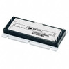
VI-2W2-EW
Vicor Corporation
DC DC CONVERTER 15V 100W
MCP6292IDR
Texas Instruments
IC OPAMP GP 2 CIRCUIT 8SOIC
ATF750C-15JI
Microchip Technology
IC CPLD 10MC 15NS 28PLCC
640550-7
TE Connectivity AMP Connectors
CONN DUST COVER 7POS CLOSED
PM10CZF120
Powerex Inc.
MOD IPM 6PAC 1200V 10A
TLC277CP
Texas Instruments
IC CMOS 2 CIRCUIT 8DIP -

RT1206BRD071K2L
YAGEO
RES SMD 1.2K OHM 0.1% 1/4W 1206
SN74F163ANS
Texas Instruments
IC BINARY COUNTER 4-BIT 16SO
ATA664251-WGQW
Microchip Technology
IC MCU 8BIT 16KB FLASH 48QFN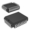
AT28BV64-30JC
Microchip Technology
IC EEPROM 64KBIT PARALLEL 32PLCC
GBPC2508
Yangjie Technology
GBPC 800V 25.0A Diodes Bridge
MT47H128M16RT-25E IT:C
Micron Technology Inc.
IC DRAM 2GBIT PARALLEL 84FBGA
AD9644BCPZ-80
Analog Devices Inc.
IC ADC 14BIT PIPELINED 48LFCSP
MK21DX256VLK5
NXP USA Inc.
IC MCU 32BIT 256KB FLASH 80FQFP
FQPF3N90
Fairchild Semiconductor
MOSFET N-CH 900V 2.1A TO220F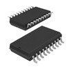
74HC541D,653
NXP USA Inc.
IC BUFF/DVR TRI-ST 8BIT 20SOIC
MX25V8035ZNI-15G
Macronix
IC FLASH 8MBIT SPI 66MHZ 8WSON
P6SMB18CA
Taiwan Semiconductor Corporation
TVS DIODE 15.3VWM 25.5VC DO214AA
AUIPS7091S
Infineon Technologies
IC PWR SWITCH N-CHAN 1:1 D2PAK-5
RP122K331D-TR
Nisshinbo Micro Devices Inc.
IC REG LIN 3.3V 400MA DFN1010-4
GALI-51+
Mini-Circuits
IC AMP CELLULAR 0HZ-4GHZ SOT89
770901-1
TE Connectivity AMP Connectors
CONN PIN 22-26AWG TIN CRIMP
IPA60R800CEXKSA1
Infineon Technologies
MOSFET N-CH 600V 5.6A TO220-FP
P4SMA91A
Meritek
TVS DIODE 77.8VWM 125VC