Square Quad Flat Package (QFP) Technology: Design, Applications, and Challenges
This guide explores Square Quad Flat Package (QFP) technology, a key innovation in integrated circuit packaging. Known for its thin pins and high pin count, QFP is needed for creating compact, reliable CPUs. Widely used in large-scale circuits, it supports device miniaturization while improving functionality and efficiency. By working seamlessly with surface-mount technology (SMT), QFP enables faster production and greater reliability in modern electronics.Catalog

Definition
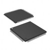
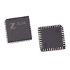
QFP, or Quad Flat Package, denotes a compact, square-shaped flat package predominantly utilized in electronic components. In the early days of graphics card design, QFPs were a common choice, providing a dependable method for mounting integrated circuits. As technology evolved, particularly with the emergence of high-speed applications surpassing 4ns, the industry gradually embraced more efficient packaging solutions, such as TSOP-II and BGA. This transition stems from a collective desire for enhanced performance and improved manufacturing capabilities. QFPs feature a distinctive design with pins protruding from all four sides, which not only aids in easy identification but also simplifies the soldering process during assembly. While this design offers benefits in various contexts, it also introduces challenges related to space efficiency and thermal management. As the demand for compact and high-performance electronic devices grows, the limitations of QFPs become increasingly evident.
Introduction
The quad flat package (QFP) is a key development in surface-mount technology, offering a compact design with leads shaped like seagull wings. This design simplifies assembly and optimizes space on printed circuit boards (PCBs). QFPs are made from ceramic, metal, or plastic, with plastic being the most common choice due to its cost-effectiveness and ease of production. Unless otherwise specified, most references to QFPs assume the plastic version. QFPs are widely used in various applications, including digital circuits like microprocessors and display drivers, as well as analog circuits such as video recorders and audio processors. They are available in different specifications, with lead pitches ranging from 1.0mm to 0.3mm and a maximum pin count of 304 at a 0.65mm pitch. In Japan, QFPs with a lead spacing of less than 0.65mm are classified as QFP (FP) to ensure precision in naming.
These packages are categorized by thickness into three main types: standard QFPs (2.0–3.6mm thick), LQFPs (Low-profile QFPs, 1.4mm), and TQFPs (Thin QFPs, 1.0mm). Additional terms, like SQFP or VQFP, are sometimes used for 0.5mm pin spacing, though this can cause confusion, highlighting the need for clear and consistent naming conventions within the industry. One major challenge with QFPs is the risk of lead bending when the pin spacing is less than 0.65mm. This issue can complicate soldering and reduce product reliability. To address this, improved versions such as BQFP (Bend-resistant QFP) and GQFP (Gold QFP) have been introduced. Multilayer ceramic QFPs are also becoming popular for high-reliability applications, reflecting growing demand for durability and performance.
Shape
QFP (Quad Flat Package) components, characterized by their high pin count and compact design, are important in diverse electronic applications such as high-frequency circuits, microprocessors, audio systems, and power circuits. Their shape enhances signal integrity, reduces interference, and optimizes space utilization, making them highly versatile. Effective thermal management and material selection are key design considerations, ensuring performance and reliability. Many often use prototyping and simulation tools to address challenges in implementation. As technology advances, QFP packages are evolving to include innovations like embedded passive components, aligning with trends toward miniaturization and integration. These features make QFP packages great in modern electronic systems.

Maintenance
Common Problems
The bending of QFP (Quad Flat Package) leads is a recurrent challenge in components that measure 28mm or larger. This predicament complicates the assembly process and may result in functional failures if not handled with care. The frequency of this issue shows the importance of understanding the various factors that contribute to lead deformation, including handling techniques, storage conditions, and environmental influences.
Repair Techniques
Training operators to treat components with a gentle touch is good for reducing lead damage. Techniques such as toe adjustment and coplanarity checks are integral in ensuring that leads are not only straightened but also positioned correctly for optimal performance. Operators need to be adept at minimizing additional bending during repairs, as applying excessive force can lead to permanent damage. Some adjustments may require repositioning individual leads, emphasizing the necessity of a careful approach to prevent excessive deformation. A systematic repair protocol can improve the longevity and reliability of the components.
Simplified Repair Method
A practical repair method involves utilizing tin-absorbing wire. By folding the wire to create a smooth midline, operators can effectively apply rosin and melt the solder. This technique allows for precise chip alignment, followed by diagonal soldering to secure it in place. Sequential welding of the pins ensures a thorough connection, which is important for the assembly's performance. In instances where chip removal is required, a similar approach can be adopted, albeit without solder absorption. Employing a thin iron wire can facilitate chip detachment by sliding it between the pins and the package, highlighting the necessity of finesse in electronic repairs.
Specific Operational Steps
When addressing QFP lead repairs, it is required to first evaluate the salvability of the component. Not every damaged part can be restored, overly bent pins may break during adjustment, leading to further complications. Operations should be conducted on an anti-static workbench, equipped with sufficient lighting and magnification to ensure precision. Utilizing templates greatly assists in aligning pins, ensuring they fit accurately into their designated spaces. These templates serve as invaluable tools for checking pin alignment and coplanarity, which are important for maintaining high-quality assembly standards. Incorporating these practices not only elevates the quality of repairs but also nurtures a culture of diligence and precision among operators.
Performance Comparison
The electrical performance of QFPs is limited by their lead frame structure, which restricts design flexibility and can increase resistance and wiring density as lead counts grow. In contrast, BGA packages, particularly PBGAs with their multilayer design, offer superior performance for high-frequency applications by reducing noise and improving power stability. BGAs also excel in thermal management, signal integrity, and assembly reliability due to their reduced coplanarity defects. However, challenges like joint invisibility after assembly require advanced inspection methods, such as infrared techniques, to ensure quality. While QFPs may suffice for simpler projects, the design flexibility and performance advantages of BGAs often make them the better choice for high-demand, compact, and efficient electronics to optimize device reliability and functionality.
About us
ALLELCO LIMITED
Read more
Quick inquiry
Please send an inquiry, we will respond immediately.

Guide to HDMI Technology
on December 30th

Complex Instruction Set Computers: How They Changed Computing?
on December 30th
Popular Posts
-

Understanding Power Supply Voltages in Electronics VCC, VDD, VEE, VSS, and GND
on June 13th 24175
-

USB-C Pinout and Features
on June 13th 21286
-

The Ultimate Guide to Wire Color Codes in Modern Electrical Systems
on January 1th 17465
-

TL494 Current-Mode PWM Controller IC
on January 1th 14733
-

Current Divider Circuits and Effective Use of the Divider Formula
on January 1th 13630
-

FET (Field Effect Transistor) Circuit Symbols
Field-Effect Transistors (FETs) are widely used in modern electronics and are found in everything from simple devices to complex digital systems. To work with these transistors effectively, it's helpful to understand the symbols that represent different types of FETs. These symbols do more than just show what the transistors look like—they also provide information about how each transistor works ...on January 1th 13440
-

Quality (Q) Factor: Equations and Applications
The quality factor, or 'Q', is important when checking how well inductors and resonators work in electronic systems that use radio frequencies (RF). 'Q' measures how well a circuit minimizes energy loss and impacts the range of frequencies the system can handle around its main frequency. In systems with inductors, capacitors, and tuned circuits, a higher 'Q' means the circuit focuses more on a spe...on January 1th 13393
-

Understanding and Building Op-Amp Based Peak Detectors
In the world of electronic circuit design, peak detectors are key tools for accurately analyzing and processing signal strengths. These circuits are designed to find and keep the highest signal amplitude, making sure the peak value is precisely captured and held as needed. Peak detectors are important in many fields, from improving audio quality in communication systems to aiding medical diagnoses...on June 13th 12497
-

LM741 Op-Amp: Features, Specifications, and Applications
The LM741 op-amp is a popular and flexible electronic component. This article goes over the pin layout, functions, specs, and different ways the LM741 can be used, while also comparing it to similar models like the LM358.Catalog1. What Is the LM741 Op-Amp?2. The LM741 Pin Configuration3. The LM741 Pin Functions4. Specifications of the LM7415. Features of LM7416. LM741 Circuit Applications7. LM741 ...on June 13th 12034
-

ST-LINK/V2: Pinout, Specifications, and Datasheet
This article takes you through the ST-LINK/V2, a well-regarded tool that amplifies connectivity and functionality. Key topics will cover its pinout configuration, delve into its 3D model, and spotlight specifications. Such understanding expands the horizons of STM microcontrollers in diverse applications. By grasping these interfaces and tools, you can transform embedded systems, opening doors to ...on January 1th 11579
