TJA1050 Transceiver Setup and Configuration Guide
The TJA1050 is a CAN transceiver that connects the CAN protocol controller to the physical bus, providing a reliable, fast, and stable way to transfer data in high-speed networks. This article covers its features, setup, and practical uses, making it easier for you to understand how the TJA1050 enhances data communication.Catalog

TJA1050 Overview
The TJA1050 acts as a link between the CAN protocol controller and the physical bus, creating a way for data to move smoothly across these points. It’s a reliable solution in high-speed environments, making it suitable for systems where fast, consistent data transfer is required. The design minimizes electromagnetic emissions, which means it helps prevent interference in other parts of the system. This feature is especially valuable in networks where other components are closely packed, and reduced emissions allow these parts to function without disruptions.
When a node is unpowered, the TJA1050 maintains stability, allowing the overall network to stay unaffected. Unlike previous transceivers, this model skips standby mode, making it ideal for partially powered networks where parts of the system may occasionally go into a power-down state without impacting the rest of the network. This capability makes it particularly helpful in automotive or industrial settings where systems often require uninterrupted connectivity.
TJA1050 Pin Configuration

| Symbol | Pin | Description |
| TXD | 1 | Transmit data input; reads in data from the CAN controller to the bus line drivers |
| GND | 2 | Ground |
| Vcc | 3 | Supply voltage |
| RXD | 4 | Receive data output; reads out data from the bus lines to the CAN controller |
| Vref | 5 | Reference voltage output |
| CANL | 6 | LOW-level CAN bus line |
| CANH | 7 | HIGH-level CAN bus line |
| S | 8 | Select input for high-speed mode or silent mode |
TJA1050 CAD Design
TJA1050 CAD Symbol

TJA1050 PCB Footprint

TJA1050 3D Model Design

Key Features of TJA1050
High-Speed Data Transmission
The TJA1050 enables rapid data transmission, reaching up to 1 Mbaud, which means it can handle high-speed networks where quick and reliable communication is a priority. This feature is especially useful in settings that require continuous, high-performance data exchange, such as automotive and industrial networks.
Compliance with ISO 11898 Standard
The TJA1050 meets the ISO 11898 standard, ensuring compatibility with other CAN-based systems. This compliance means you can integrate it into various networks without compatibility issues, making it a versatile choice for different projects.
Low Electromagnetic Emission (EME)
With its low electromagnetic emission design, the TJA1050 helps reduce the risk of interference with nearby electronic devices. This feature allows the transceiver to operate effectively, even in environments where devices are closely spaced, like automotive or industrial settings.
Wide Common-Mode Range for Electromagnetic Immunity (EMI)
The TJA1050’s broad common-mode range improves its immunity to electromagnetic interference, helping it maintain stable performance in environments with high electromagnetic noise. This stability is essential for ensuring that data transmission remains unaffected by external disturbances.
Unpowered Node Stability
One of the TJA1050’s unique benefits is its ability to keep the CAN bus stable even when some nodes are unpowered. This feature is valuable in applications where parts of the network may power down occasionally, allowing the rest of the system to function without disruptions.
Transmit Data (TXD) Dominant Time-Out
The TXD dominant time-out function prevents transmission errors by automatically stopping transmission if a dominant state is held for too long. This feature helps protect the network from unintentional interference or signal disruption, supporting overall network stability.
Silent Mode
The silent mode feature lets you disable the transmitter, making the TJA1050 ideal for monitoring or diagnostics. This allows the device to observe network activity without sending any signals, which is helpful in systems where you need to avoid disturbing ongoing data traffic.
Protection Against Automotive Transients
The TJA1050 includes built-in protection against automotive transients, which shields it from sudden voltage spikes. This durability ensures the transceiver can operate reliably in vehicles, where voltage fluctuations are common due to various electrical systems.
Compatibility with 3.3V and 5V Devices
Compatible with both 3.3V and 5V devices, the TJA1050 works well across different systems, giving you flexibility in designing and integrating the transceiver into your projects without voltage compatibility concerns.
Thermal and Short-Circuit Protection
The TJA1050 is equipped with thermal protection and short-circuit resilience, guarding it against overheating and accidental connections to battery or ground. These features improve the device’s durability, making it a reliable choice in applications with high safety and performance demands.
Supports Up to 110 Nodes
With support for up to 110 nodes, the TJA1050 can connect many devices within a network, making it suitable for large systems. This capacity is beneficial in applications where numerous devices need to communicate effectively without overloading the network.
TJA1050 Functional Block Diagram
The TJA1050’s block diagram visually represents the way this component manages data flow. It illustrates how the transceiver sends and receives data signals, maintaining a balanced output between the CANH (high-level) and CANL (low-level) lines. This balance is key to controlling electromagnetic interference, enabling the device to handle high data rates with ease. Each section of the block diagram shows how data is processed and transmitted, which helps you understand the device’s overall operation.
It’s designed with flexibility, handling speeds up to 1 Mbaud while staying compliant with CAN standards, including ISO 11898. This approach allows the TJA1050 to adapt to various applications seamlessly, showing the device’s functionality and stability in high-speed data communication environments.

TJA1050 Circuit and Applications

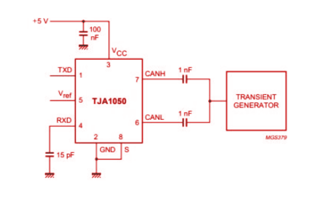
TJA1050 Automotive Transient Test Circuit
TJA1050 Specifications
Technical specifications, attributes, parameters, and comparable parts for NXP USA Inc. TJA1050T/N,118.
| Type | Parameter |
| Mounting Type | Surface Mount |
| Package / Case | 8-SOIC (0.154, 3.90mm Width) |
| Surface Mount | YES |
| Operating Temperature | -40°C ~ 150°C |
| Packaging | Tape & Reel (TR) |
| Published | 2002 |
| JESD-609 Code | e0 |
| Part Status | Obsolete |
| Moisture Sensitivity Level (MSL) | 1 (Unlimited) |
| Number of Terminations | 8 |
| Type | Transceiver |
| HTS Code | 8542.39.00.01 |
| Voltage - Supply | 4.75V ~ 5.25V |
| Terminal Position | DUAL |
| Terminal Form | GULL WING |
| Peak Reflow Temperature (Cel) | NOT SPECIFIED |
| Number of Functions | 1 |
| Supply Voltage | 5V |
| Terminal Pitch | 1.27mm |
| Time@Peak Reflow Temperature-Max (s) | NOT SPECIFIED |
| Base Part Number | TJA1050 |
| Pin Count | 8 |
| JESD-30 Code | R-PDSO-G8 |
| Qualification Status | Not Qualified |
| Power Supplies | 5V |
| Supply Current-Max | 0.075mA |
| Data Rate | 1000 Mbps |
| Protocol | CANbus |
| Number of Drivers/Receivers | 1/1 |
| Duplex | Half |
| Receiver Hysteresis | 70mV |
| Number of Transceivers | 1 |
| Length | 4.9mm |
| Height Seated (Max) | 1.75mm |
| Width | 3.9mm |
| RoHS Status | ROHS3 Compliant |
Frequently Asked Questions [FAQ]
1. What is the difference between TJA1050 and MCP2551?
The TJA1050 and MCP2551 both act as interfaces between the CAN protocol controller and the physical CAN bus, but they have unique features. The TJA1050 is designed for high-speed CAN networks, supporting differential transmission and reception between the controller and bus. It’s suitable for networks where nodes may be powered down without affecting the rest of the system. The MCP2551, on the other hand, also supports high-speed CAN but is known for its fault tolerance, protecting the controller from high-voltage spikes caused by external sources like EMI and ESD. This feature provides an extra layer of stability on the bus, especially in environments prone to electrical noise.
2. What are the typical CAN voltage levels?
CAN bus voltage levels vary depending on the line. On the CANH (high) line, the voltage usually sits between 2.5 and 3.5 volts when idle, typically around 2.7 to 3.3 volts during operation. On the CANL (low) line, the voltage generally ranges from 1.5 to 2.5 volts when idle and between 1.7 to 2.3 volts in running conditions. These levels help maintain a clear differential signal, which is necessary for reliable data transmission on the CAN bus.
3. Under what conditions does the TJA1050 operate?
The TJA1050 operates within a supply voltage range of 4.75V to 5.25V. It’s a compact module, measuring 22.0 mm in length, 11.5 mm in width, and 3.3 mm in height, with a weight of about 0.8 to 1.0 grams. The TJA1050 can support up to 110 nodes, making it suitable for larger CAN networks where multiple devices need to communicate seamlessly.
4. Can a Raspberry Pi communicate with a CAN bus?
Raspberry Pi doesn’t come with a built-in CAN bus interface, but it does include an SPI bus on its GPIO pins, which is widely supported by many CAN controllers. The SPI bus uses four connections: MOSI (Master Out Slave In), MISO (Master In Slave Out), SCLK (Serial Clock), and CS (Chip Select), allowing the Raspberry Pi to interface with a CAN transceiver module for CAN communication.
5. How does the MCP2515 CAN bus controller interface with the TJA1050 driver and SPI interface?
The MCP2515 CAN module, combined with the TJA1050 transceiver, enables CAN communication through an SPI interface. This module meets CAN V2.0B standards and supports data rates of up to 1 Mbps. It operates on a 5V DC power supply and has an 8MHz crystal oscillator with a 120Ω termination resistor for signal stability. By connecting to an SPI interface on microcontrollers like Arduino, this module allows seamless control over CAN bus devices, enabling applications in long-distance data transmission and signal radiation prevention.
About us
ALLELCO LIMITED
Read more
Quick inquiry
Please send an inquiry, we will respond immediately.
LT1085 Low Dropout Voltage Regulator
on October 29th
All About the LMV358 Operational Amplifier
on October 29th
Popular Posts
-

Complex Instruction Set Computers: How They Changed Computing?
on April 18th 147749
-

USB-C Pinout and Features
on April 18th 111920
-

Using Xilinx Unified Simulation Primitives: A Comprehensive Guide to FPGA Design and Simulation
on April 18th 111349
-

Power Supply Voltages in Electronics: Meaning of VCC, VDD, VEE, VSS, and GND
on April 18th 83714
-

RJ45 Connector Guide: Pinout, Wiring, Cable Types, and Uses
on January 1th 79502
-

The Ultimate Guide to Wire Color Codes in Modern Electrical Systems
The way our electrical systems use colors isn’t just for looks. Each wire color now indicates a specific function, making it easier to identify and handle electrical components correctly during ins...on January 1th 66872
-

Quality (Q) Factor: Equations and Applications
The quality factor, or 'Q', is important when checking how well inductors and resonators work in electronic systems that use radio frequencies (RF). 'Q' measures how well a circuit minimizes energy...on January 1th 63005
-

Purge Valve Guide: Function, Symptoms, Testing, and Replacement for Optimal Engine Performance
The purge valve is a key part of a car’s system that helps keep the air clean by managing fuel vapors before they can escape into the atmosphere. This not only helps the environment by reducing pol...on January 1th 62952
-

Achieving Peak Performance with the Maximum Power Transfer Theorem
The Maximum Power Transfer Theorem explains how energy from a source, such as a battery or generator, flows to a connected load. It shows the exact condition where the load receives the most power....on January 1th 54078
-

A23 Battery Specifications and Compatibility
The A23 battery is a small, cylinder-shaped battery with high voltage. Also called 23A, 23AE, or MN21, it runs at 12 volts and much higher than AA or AAA batteries. Its special design make...on January 1th 52092
HOT Part Number
-

BD9B100MUV-E2
Rohm Semiconductor
IC REG BUCK ADJ 1A 16VQFN
UPD70F3539AF5A9-PN7-Q-A
Renesas Electronics America Inc
IC MICROCONTROLLER
18081A621JAT2A
KYOCERA AVX
CAP CER 620PF 100V NP0 1808
FDN340P
onsemi
MOSFET P-CH 20V 2A SUPERSOT3
70231-101
Amphenol ICC (FCI)
CONN RCPT BLADE PWR 8POS EDGE MT
MPSW42RLRAG
onsemi
TRANS NPN 300V 0.5A TO92
MC7824BT
onsemi
IC REG LINEAR 24V 1A TO220AB
AD8009ARZ-REEL
Analog Devices Inc.
IC OPAMP CFA 1 CIRCUIT 8SOIC
LT1815CS5#TRPBF
Analog Devices Inc.
IC OPAMP VFB 1 CIRCUIT TSOT23-5
DG411DYZ
Renesas Electronics America Inc
IC SWITCH SPST-NCX4 35OHM 16SOIC
VFT2060C-M3/4W
Vishay General Semiconductor - Diodes Division
DIODE SCHOTTKY 20A 60V ITO-220AB
TSX562AIYST
STMicroelectronics
IC CMOS 2 CIRCUIT 8MINISO
MR256D08BMA45
Everspin Technologies Inc.
IC RAM 256KBIT PARALLEL 48FBGA
VSC3312YYP-01
Microchip Technology
IC SWITCH 16X16 6.5GBPS 196FCBGA
XC68HC908GP20CFB
Motorola
TSG 8BIT20K FLASH
CSR8811A08-ICXR-R
Qualcomm
IC RF TXRX+MCU BLUETOOTH
MPSW05
onsemi
TRANS NPN 60V 0.5A TO92
1N4055R
Solid State Inc.
DIODE GEN PURP REV 900V 275A DO9 -

ASX342ATSC00XPED0-DP
onsemi
IMAGE SENSOR VGA 1/4 CIS SOC
0433.125NR
Littelfuse Inc.
FUSE BOARD MNT 125MA 125VAC/VDC
1SMA5941BT3G
onsemi
DIODE ZENER 47V 1.5W SMA
DCP010512BP-U/700
Texas Instruments
DC DC CONVERTER 12V 1W
1-1734344-1
TE Connectivity AMP Connectors
CONN D-SUB HD RCPT 15P R/A SLDR
KSD1621STF
onsemi
TRANS NPN 25V 2A SOT89-3
BQ24161RGET
Texas Instruments
IC BATT CHG LI-ION 1CELL 24VQFN
BTA26-600BW
STMicroelectronics
TRIAC ALTERNISTOR 600V 25A TOP3
NCP1239DD65R2G
onsemi
IC OFFLINE SWITCH FLYBACK 7SOIC
TMS320TCI6482BZTZA
Texas Instruments
TMS320 - DIGITAL SIGNAL PROCESSO
BQ20Z90DBTR-V150
Texas Instruments
IC GAS GAUGE LI-ION 30TSSOP
PCMB104T-1R0MT
Susumu
FIXED IND 1UH 18A 3.3 MOHM SMD
CY29942AXCT
Infineon Technologies
IC CLK BUFFER 1:18 200MHZ 32TQFP
CC0402KRX7R9BB561
YAGEO
CAP CER 560PF 50V X7R 0402
STPS20M60SG-TR
STMicroelectronics
DIODE SCHOTTKY 60V 20A D2PAK
AT25010N-10SC-2.7
Microchip Technology
IC EEPROM 1KBIT SPI 3MHZ 8SOIC
04023A1R0CAT4A
KYOCERA AVX
CAP CER 1PF 25V C0G/NP0 0402
ISL6327IRZ
Intersil
SWITCHING CONTROLLER, VOLTAGE-MO -

LQW18AN75NG0ZD
Murata Electronics
FIXED IND
DFA100BA160
SanRex Corporation
DIODE MODULE 1600V 100A
BAR46AFILM
STMicroelectronics
DIODE ARRAY SCHOTTKY 100V SOT23
MAX825SEUK
Analog Devices Inc./Maxim Integrated
IC SUPERVISOR MPU
MMST2222A-7-F
Diodes Incorporated
TRANS NPN 40V 0.6A SOT323
FODM8801AR2
onsemi
OPTOISO 3.75KV TRANS 4-MINI-FLAT
FJV1845FMTF
Fairchild Semiconductor
SMALL SIGNAL BIPOLAR TRANSISTOR,
EVK105RH5R1JW-F
Taiyo Yuden
CAP CER 5.1PF 16V R2H 0402
6651170-3
TE Connectivity AMP Connectors
CONN EDGE DUAL FMALE 4POS 0.508
KSZ8893FQLI-FX
Microchip Technology
IC SWITCH ETH 3PORT 128QFP
170M6340
Eaton - Bussmann Electrical Division
FUSE SQUARE 400A 1.3KVAC RECT
BCM20741A2KFB1G
Broadcom Limited
SINGLE-CHIP BLUETOOTH
MAX3443EASA+
Analog Devices Inc./Maxim Integrated
IC TRANSCEIVER HALF 1/1 8SOIC
GRM0335C1H9R3DA01D
Murata Electronics
CAP CER 9.3PF 50V C0G/NP0 0201
TNY175PN
Power Integrations
11.5 W (85-265 VAC) 15 W (230 VA
742700726
Würth Elektronik
FERRITE CORE 278 OHM SOLID 4MM
DM74S20N
onsemi
IC GATE NAND 2CH 4-INP 14DIP
P4SMA56CA-E3/61
Vishay General Semiconductor - Diodes Division
TVS DIODE 47.8VWM 77VC DO214AC