The Complete Guide to Electronic Component Schematic Symbols
This guide explains what schematic symbols are and how they are used to show electronic components in circuit diagrams. You’ll learn about different types of symbols for power sources, resistors, capacitors, transistors, motors, speakers, and many more. It also covers the standard rules (like IEC, ANSI, and IPC) that make these symbols the same around the world. Whether you're fixing, building, or learning about electronics, knowing these symbols helps you understand circuits more easily.Catalog

What is an Electronic Component Schematic Symbol?
Schematic symbols are simplified visual representations used in electronic circuit diagrams. Rather than showing the physical appearance of components, they illustrate how components function and connect within a system. This simplification helps focus on how electricity flows and how components interact, rather than on how they look or are built. The main purpose of these symbols is to turn complex circuitry into diagrams that are easier to understand and work with. A well-drawn schematic can be interpreted by anyone, regardless of their background or location. This universal language makes collaboration and troubleshooting more efficient.
Using symbolic icons instead images reduces visual clutter in diagrams. It highlights logical relationships between parts and supports faster understanding of the circuit’s design. For example, a single symbol can represent an entire relay or integrated circuit. This allows to focus on the system’s overall behavior rather than getting lost in the intricate details of individual components. These abstractions also play a role when diagnosing problems, planning upgrades, or explaining system behavior to others. They're valuable in dense or complex systems such as embedded controllers or radio-frequency modules.
Standardization of Schematic Symbols
IEC 60617
Developed and maintained by the International Electrotechnical Commission (IEC), IEC 60617 is one of the most comprehensive international standards for graphical symbols used in electrical and electronic diagrams. It includes thousands of standardized symbols covering everything from resistors and capacitors to more complex electromechanical components. The goal of IEC 60617 is to promote a uniform visual language that can be applied globally in technical drawings. It’s widely adopted in fields ranging from education and design to manufacturing and maintenance. Access to the complete symbol library is provided through an online database. This database is regularly updated to reflect new technologies and evolving industry practices.
IEEE/ANSI 315 (1975)
Published by the Institute of Electrical and Electronics Engineers (IEEE) in collaboration with the American National Standards Institute (ANSI), IEEE/ANSI 315 was the go-to standard in North America for many decades. First released in 1975, it provided a clear, consistent set of symbols for electrical and electronic diagrams and played a role in shaping engineering education and technical documentation throughout the late 20th century. Although it was officially withdrawn in 2019, it continues to be a reference for legacy systems and historical documentation. Many rely on this standard to accurately interpret and maintain vintage or long-lived systems. Its influence is still evident in many engineering tools and textbooks.
IPC-2612-1
Issued by the IPC (Association Connecting Electronics Industries), IPC-2612-1 is a modern standard that addresses the creation and application of graphical symbols specifically in electronic design automation (EDA) environments. Unlike older standards that were developed with hand-drawing or 2D CAD in mind, IPC-2612-1 is tailored for the digital workflows used in today's ECAD (Electronic Computer-Aided Design) platforms. It provides detailed guidance on how symbols should be constructed, formatted, and integrated into component libraries, which is valuable for design teams building custom or standardized parts for printed circuit board (PCB) layout and simulation. By harmonizing the representation of symbols across various software platforms, IPC-2612-1 helps reduce errors, improve team collaboration, and support more efficient manufacturing processes.
Power Supply Symbols
These schematic symbols represent different types of power sources that provide electrical energy to a circuit. Understanding these symbols is needed for interpreting and designing circuit diagrams.
AC Power Source
The AC power symbol typically appears as a circle with a sine wave inside or simply a pair of terminals labeled “AC.” This represents a source of alternating current, where the direction of flow reverses periodically usually 50 or 60 times per second, depending on the region. AC power is the standard form of electricity supplied by utility companies and is commonly used in homes, businesses, and industrial facilities. It’s ideal for transmitting power over long distances due to its ability to be easily transformed to different voltages using transformers.
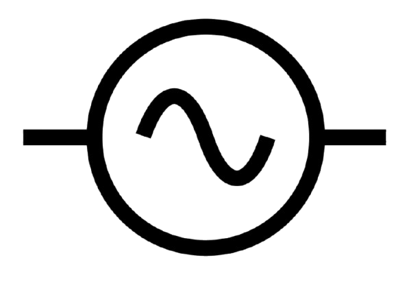
Figure 2. AC Power Supply Symbol
DC Power Source
The symbol for a DC power source usually features two parallel lines, one longer (positive) and one shorter (negative). In some variations, an arrow is included to indicate that the voltage is adjustable. This type of source provides a steady, unidirectional flow of electric charge. DC power is important in electronics, especially in circuits requiring a consistent voltage level. It’s commonly supplied by power adapters, solar panels, and regulated power supplies used in laboratories and prototyping.

Figure 2. DC Power Source Symbol
Battery
The battery symbol is composed of alternating long and short lines, representing the positive and negative terminals of one or more electrochemical cells. This symbol indicates a self-contained DC power source that stores energy chemically. Batteries are good for portable electronics, such as smartphones and laptops, as well as for backup power in systems like alarms and emergency lighting. The number of cell symbols used often corresponds to the voltage level of the battery, with more cells representing higher voltage output.
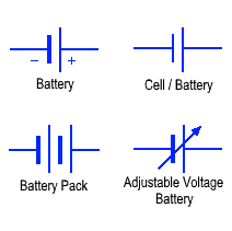
Figure 3. Battery/Cell Symbol
Passive Component Symbols
Passive components are important building blocks in electrical and electronic circuits. Unlike active components (like transistors or diodes), passive components do not generate power or amplify signals. Instead, they respond to electrical energy and influence how signals behave, often by storing or dissipating energy. Here are the main types of passive components and their standard circuit symbols:
Resistors
Resistors are components that limit or control the flow of electric current within a circuit. The most common type is the fixed resistor, typically represented by a zigzag or rectangular line, which has a constant resistance value. Variable resistors, such as potentiometers and rheostats, are depicted with an arrow across the resistor symbol, indicating that their resistance can be manually adjusted. Specialized resistors also exist, including thermistors, which are temperature-sensitive and marked with a diagonal line or arrow through the symbol; their resistance changes in response to temperature variations. Similarly, photoresistors also known as light-dependent resistors (LDRs) alter their resistance based on light intensity and are often symbolized with arrows pointing toward the resistor to denote incoming light. Each of these resistor types plays a unique role in regulating current under varying environmental or operational conditions.

Figure 4. Resistors Symbol
Capacitors
Capacitors are components that store and release electrical energy in the form of an electric field, playing a role in timing, filtering, and energy storage applications. Non-polarized capacitors, often used in AC circuits or where polarity is not a concern, are represented in circuit diagrams by two parallel lines of equal length, symbolizing the plates. In contrast, polarized capacitors, such as electrolytic or tantalum types, have a specific polarity and are used primarily in DC circuits; their symbols feature one straight line and one curved line or include a plus sign to indicate the positive terminal. Additionally, variable capacitors, which allow for the adjustment of capacitance, are depicted with an arrow drawn across or through the capacitor symbol, reflecting their tunable nature.

Figure 5. Capacitor Symbol
Inductors
Inductors are passive components that store energy in a magnetic field when electric current flows through them. Their primary function is to resist changes in current, which makes them especially useful in filtering, tuning, and timing applications. In circuit diagrams, standard inductors are represented by a series of loops or a coiled wire symbol. When the inductor contains a magnetic core, often used to increase inductance, this is shown with lines or rectangles near or inside the coil, indicating an iron-core inductor. Variable inductors, which allow the inductance to be adjusted, are depicted with an arrow passing through the coil, following a similar convention used for other adjustable components like variable resistors and capacitors.

Figure 6. Inductors Symbol
Transformers
Transformers are passive components that transfer electrical energy between two or more circuits through the principle of electromagnetic induction. They are commonly used to step voltage levels up or down in power distribution and signal isolation. In schematic diagrams, transformers are typically represented by two inductive coils placed side by side, often with parallel lines between them to indicate a magnetic core. Dots or marks near the coils may be used to show winding polarity or phase relationships. The style and number of coil turns depicted can suggest whether the transformer is configured for stepping voltage up or down. Some transformers also feature a center tap, an additional connection on the primary or secondary winding which is useful in power supply circuits and audio applications where dual voltage outputs or phase splitting is required.

Figure 7. Transformers Symbol
Semiconductor Device Symbols

Figure 8. Semiconductor Device Symbols
Semiconductor device symbols are used in circuit diagrams to show important parts that control electricity in electronic devices. These parts are called “active components” because they can change, direct, or boost electrical signals. They are used in almost everything electronic from computers and phones to lights and speakers. One common type is the diode. A diode lets electricity flow in only one direction, kind of like a one-way street. This is useful for changing AC (alternating current) into DC (direct current), which many devices need. There are different types of diodes. Zener diodes can let electricity flow backward when the voltage is high enough, which helps control voltage. LEDs (light-emitting diodes) light up when electricity passes through them. Photodiodes create electricity when they sense light, which makes them useful in sensors. A bridge rectifier is made of four diodes and is often used in power supplies to turn AC into DC.
Another key part is the transistor. Transistors can act like a switch that turns electricity on and off, or they can make signals stronger. There are different kinds of transistors, like NPN and PNP (which are types of bipolar transistors), and JFETs, which are controlled by voltage. Transistors are used in almost every electronic device and are especially important in computers. Integrated circuits (ICs) are small chips that contain many tiny electronic parts inside them. In a diagram, they look like rectangles. These chips can do many jobs, depending on what’s inside. Some ICs are logic gates, which do basic math and decision-making in computers. Others, like operational amplifiers (op-amps), are used to increase signal strength or control sound and light in devices.
Electromechanical Device Symbols
Electromechanical components are devices that convert electrical energy into physical motion, sound, or other mechanical effects. In circuit diagrams, these components are represented by standardized symbols that not only depict the type of device but also often indicate how it is activated or connected within a circuit. A relay is an electrically operated switch that uses an electromagnet to mechanically operate one or more sets of contacts. When current flows through the coil, it generates a magnetic field that pulls the switch closed or open. Relay symbols typically show the coil and the corresponding switch contacts, illustrating how the relay operates within the circuit.

Figure 9. Symbol Of Relay in Electrical Circuit
Motors transform electrical energy into rotary motion, powering a wide range of mechanical systems. Circuit symbols for motors often include the letter "M" and may show connections for power and control, indicating whether the motor is AC or DC. Buzzers produce audible signals when electrical current is applied. These components are used for alerts, alarms, or notifications in electronic systems. Their schematic symbols may include wave lines or a stylized speaker, representing the sound-producing function. A fuse is a safety device that protects electrical circuits from overcurrent by melting and breaking the connection when the current exceeds a certain threshold. Fuse symbols typically consist of a small rectangle or a line with a central bar, representing the breakable element. These symbols not only identify the devices themselves but also provide clues about how and when they are activated within the circuit. For example, a relay symbol may show a control line connected to a switch, while a motor symbol might be paired with a capacitor or driver circuit. Understanding these symbols is important for interpreting and designing functional and safe electronic schematics.

Figure 10. Symbol of Motor, Fuse and Buzzer
Measurement and Diagnostic Symbols
These symbols represent instruments commonly used for observing, measuring, and diagnosing the behavior of electrical and electronic circuits:
Voltmeters and Ammeters used to measure electrical potential (voltage) and current flow, respectively. A voltmeter is typically connected in parallel across a component to measure voltage, while an ammeter is connected in series to measure current through a circuit. These tools are good for evaluating circuit performance and identifying faults. Galvanometers are sensitive instruments designed to detect and measure very small currents. Often used in analog systems, galvanometers can indicate current direction and are foundational components in analog meter displays. Oscilloscopes allow visualization of electrical signals over time. By displaying voltage waveforms on a screen, oscilloscopes help analyze signal behavior, frequency, amplitude, and timing. They are great in troubleshooting, waveform analysis, and testing signal integrity in complex circuits.

Figure 11. Voltmeters and Ammeters Symbol

Figure 12. Galvanometer and Oscilloscope Symbol
Audio and Communication Symbols
These symbols are commonly found on devices that handle the transmission or reception of audio and communication signals. They help identify key components involved in sound processing and signal exchange in various electronic systems. Microphones represent components that capture sound waves and convert them into electrical signals. Microphones are good in applications such as voice recording, video conferencing, and live sound systems. The symbol resembles a small vertical cylinder or stylized sound pickup device. Speakers indicate devices that convert electrical signals back into audible sound. Found in everything from mobile phones to PA systems, speakers play a role in delivering audio output. Their symbol often looks like a cone or a stylized sound wave emitting from a box. Telecom and RF (Radio Frequency) Ports identify ports used to connect communication devices, including telephones, antennas, and wireless modules. They serve as entry and exit points for data and audio signals in wired and wireless communication systems. The symbols may vary but often include waveforms or antenna imagery to denote signal flow.

Figure 13. Audio and Communication Symbols
Digital Logic and Interface Symbols
Digital logic and interface symbols are important tools in the design and interpretation of circuits that process binary data. These symbols serve as a visual shorthand for representing the components and pathways within digital systems, particularly in embedded systems, automation controls, and computing platforms. Logic gates, such as AND, OR, and XOR, form the foundation of digital decision-making by performing specific logical operations based on binary inputs. They are used to implement control logic, signal processing, and data flow within circuits. Buses and branching boxes help manage the complexity of signal routing by representing grouped data lines and allowing organized distribution of signals between different parts of a system. These elements are great for maintaining clarity in schematic diagrams and ensuring efficient data communication. Potentiometers, while often associated with analog circuits, also play a role in digital systems by enabling manual adjustment of signal levels, especially in scenarios where analog input needs to be interpreted digitally. Together, these symbols not only guide the construction and analysis of digital circuits but also enable clear communication across various fields of technology.

Figure 14. Logic Gate Symbols
Conclusion
Schematic symbols make it easier to read, design, and fix electronic circuits. They are like a common language that people everywhere can understand, no matter what country they’re from. This guide shows how each symbol stands for a part in a circuit and helps you understand what that part does. When you know these symbols well, you can build better circuits, solve problems faster, and work more confidently with electronics.
About us
ALLELCO LIMITED
Read more
Quick inquiry
Please send an inquiry, we will respond immediately.
Frequently Asked Questions [FAQ]
1. What are electronics schematic symbols?
Electronics schematic symbols are simplified drawings used to represent components in a circuit diagram. Instead of showing the physical shape of parts like resistors, capacitors, or diodes, these symbols act as visual shortcuts that make circuit layouts easier to understand. Each symbol corresponds to a specific electronic part and shows how it connects within the circuit. For example, a resistor is usually drawn as a zigzag line, and a capacitor as two parallel lines. These symbols help quickly interpret how a circuit works without needing to see the real components.
2. How to read an electrical schematic diagram?
To read an electrical schematic diagram, start by recognizing the symbols used for different components like resistors, transistors, switches, and power sources. Next, follow the lines that connect them, these lines represent wires or traces that carry electrical signals. Where two lines meet with a dot, it means they’re electrically connected; if there's no dot, they just cross each other without contact. Most diagrams are designed to flow from left to right or top to bottom, showing the direction of power or signal. Also, pay attention to labels like R1 or C2, which help identify each component in the circuit. Understanding these basics lets you follow the function and structure of the system.
3. What is the standardization of symbols?
Standardization of schematic symbols means that the electronics industry follows common rules for drawing and using symbols in diagrams. This ensures that anyone looking at a schematic can understand it the same way. Organizations like the IEEE, IEC, and ANSI create and maintain these standards to keep designs consistent, accurate, and universal. Without standardization, different symbols for the same part could cause confusion or errors in building or fixing circuits. Following standards also makes it easier to document, share, and update electronic designs across teams and projects.
4. What is ANSI standard symbols?
ANSI standard symbols refer to the set of official schematic symbols created by the American National Standards Institute. These are mostly used in the United States for electrical and electronic diagrams. ANSI symbols are part of structured standards like ANSI Y32.2, which define how to draw components in wiring diagrams, control systems, and industrial schematics. The purpose is to make diagrams clear and uniform so everyone can read and work with them without confusion. Using ANSI symbols helps maintain quality and communication across different industries and technical teams.
5. Is there a standard for P&ID symbols?
Yes, P&ID (Piping and Instrumentation Diagram) symbols are standardized to ensure clear and consistent communication in process and control systems. The most widely used standard for these symbols is ISA 5.1, provided by the International Society of Automation. This standard defines how to represent elements like valves, pumps, sensors, piping, and control instruments. P&IDs are commonly used in industries such as oil and gas, water treatment, chemical plants, and manufacturing. Using standardized symbols helps everyone understand how the system works, how it’s controlled, and how each part connects within the larger process.

MC7447ATHX1000NB Overview and Specs
on March 25th

Capacitor Symbols: A Complete Guide to Capacitor Types in Circuit Diagrams
on March 21th
Popular Posts
-

Complex Instruction Set Computers: How They Changed Computing?
on April 18th 147749
-

USB-C Pinout and Features
on April 18th 111901
-

Using Xilinx Unified Simulation Primitives: A Comprehensive Guide to FPGA Design and Simulation
on April 18th 111349
-

Power Supply Voltages in Electronics: Meaning of VCC, VDD, VEE, VSS, and GND
on April 18th 83714
-

RJ45 Connector Guide: Pinout, Wiring, Cable Types, and Uses
on January 1th 79502
-

The Ultimate Guide to Wire Color Codes in Modern Electrical Systems
The way our electrical systems use colors isn’t just for looks. Each wire color now indicates a specific function, making it easier to identify and handle electrical components correctly during ins...on January 1th 66867
-

Quality (Q) Factor: Equations and Applications
The quality factor, or 'Q', is important when checking how well inductors and resonators work in electronic systems that use radio frequencies (RF). 'Q' measures how well a circuit minimizes energy...on January 1th 63004
-

Purge Valve Guide: Function, Symptoms, Testing, and Replacement for Optimal Engine Performance
The purge valve is a key part of a car’s system that helps keep the air clean by managing fuel vapors before they can escape into the atmosphere. This not only helps the environment by reducing pol...on January 1th 62936
-

Achieving Peak Performance with the Maximum Power Transfer Theorem
The Maximum Power Transfer Theorem explains how energy from a source, such as a battery or generator, flows to a connected load. It shows the exact condition where the load receives the most power....on January 1th 54074
-

A23 Battery Specifications and Compatibility
The A23 battery is a small, cylinder-shaped battery with high voltage. Also called 23A, 23AE, or MN21, it runs at 12 volts and much higher than AA or AAA batteries. Its special design make...on January 1th 52087
HOT Part Number
-

XC3S50A-4VQG100C
AMD
IC FPGA 68 I/O 100VQFP
SI1102-A-GM
Silicon Labs
SENSOR OPT REFLECTIVE 50CM 8WDFN
TCN4-13+
Mini-Circuits
1:4 LTCC TRANSFORMER, 650 - 1250
VF30100S-E3/4W
Vishay General Semiconductor - Diodes Division
DIODE SCHOTTKY 100V 30A ITO220AB
GRM033R70J103KA01D
Murata Electronics
CAP CER 10000PF 6.3V X7R 0201
QMK212B7102MDHT
Taiyo Yuden
CAP CER 1000PF 250V X7R 0805
M82351G-12
MACOM Technology Solutions
ACCESS VOICE PROCESSOR
74LV132D,112
Nexperia USA Inc.
IC GATE NAND SCHMIT 4CH 2IN 14SO
AH1801-FJG-7
Diodes Incorporated
MAG SWITCH OMNIPOLAR DFN2020B-3
DG412DY-T1-E3
Vishay Siliconix
IC SWITCH SPST-NOX4 35OHM 16SOIC
PIC16F876A-I/SO
Microchip Technology
IC MCU 8BIT 14KB FLASH 28SOIC
LXA08FP600
Power Integrations
DIODE GP 600V 8A TO220 FULL PACK
FM25V20A-DG
Infineon Technologies
IC FRAM 2MBIT SPI 40MHZ 8DFN
CY7C1011CV33-10ZXC
Cypress Semiconductor Corp
IC SRAM 2MBIT PARALLEL 32TSOP II
04023C221KAT2A
KYOCERA AVX
CAP CER 220PF 25V X7R 0402
RO3101A
Murata Electronics
SAW RES 433.9200MHZ SMD
XRD9818ACGTR
MaxLinear, Inc.
IC AFE 3 CHAN 16BIT 28TSSOP
CL21F104ZBANNNC
Samsung Electro-Mechanics
CAP CER 0.1UF 50V Y5V 0805 -

BZT52-B16_R1_00001
Panjit International Inc.
SOD-123, ZENER
P0300ECL
Littelfuse Inc.
THYRISTOR 25V 400A TO226-2
TPS73615DBVTG4
Texas Instruments
IC REG LINEAR 1.5V 400MA SOT23-5
SN74AXC4T774BQBR
Texas Instruments
IC TRANSCEIVER HALF 4/4 16WQFN
170M5954
Eaton - Bussmann Electrical Division
FUSE SQUARE 350A 1KVAC RECT
CC0805KRX7R9BB682
YAGEO
CAP CER 6800PF 50V X7R 0805
SRP7028A-6R8M
Bourns Inc.
FIXED IND 6.8UH 4.5A 60 MOHM SMD
SMAJ150CA
Taiwan Semiconductor Corporation
TVS DIODE 150VWM 243VC DO214AC
PE-68675
Pulse Electronics
IC CHIP
MAX14890EATJ+
Analog Devices Inc./Maxim Integrated
IC RECEIVER 0/4 32TQFN
TFZGTR20B
Rohm Semiconductor
DIODE ZENER 20V 500MW TUMD2
1N5406-E3/73
Vishay General Semiconductor - Diodes Division
DIODE GEN PURP 600V 3A DO201AD
ME501610
Powerex Inc.
BRIDGE RECT 3P 1.6KV 100A MODULE
GRM1555C2A5R8DA01D
Murata Electronics
CAP CER 5.8PF 100V C0G/NP0 0402
MRF8S19140HSR3
NXP USA Inc.
FET RF 65V 1.96GHZ NI780HS
TN2130K1-G
Microchip Technology
MOSFET N-CH 300V 85MA TO236AB
ADL5519ACPZ-R7
Analog Devices Inc.
IC AMP LOG DETECT CTRLR 32LFCSP
SP3222ECT-L
MaxLinear, Inc.
IC TRANSCEIVER FULL 2/2 18SOIC -
502AT-2
Semitec USA Corp
NTC THERMISTORS 5KOHM 1%
NFM18CC101R1C3D
Murata Electronics
CAP FEEDTHRU 100PF 20% 16V 0603
PS2562L-1-F3-A
Renesas Electronics America Inc
OPTOISOLATOR 5KV DARL 4SMD
502494-0370
Affinity Medical Technologies - a Molex company
2.0 W/B SGL R/ARECASSY3CKTEMBSTP
C1206C223K5RACTU
KEMET
CAP CER 0.022UF 50V X7R 1206
NIS5102QP2HT1G
onsemi
IC HOT SWAP CTRLR GP 12PLLP
VI-J62-MY
Vicor Corporation
DC DC CONVERTER 15V 50W
ADR441ARMZ-REEL7
Analog Devices Inc.
IC VREF SERIES 0.12% 8MSOP
MIC5200-5.0BS
Microchip Technology
IC REG LINEAR 5V 100MA SOT223-3
TAS3251DKQR
Texas Instruments
IC AMP D MONO/STER 350W 56HSSOP
GRM1886T1H360JD01D
Murata Electronics
CAP CER 36PF 50V T2H 0603
TZM5249B-GS08
Vishay General Semiconductor - Diodes Division
DIODE ZENER 19V 500MW SOD80
LM2575-5.0YWM
Microchip Technology
IC REG BUCK 5V 1A 24SOIC
RT0402BRE075K6L
YAGEO
RES SMD 5.6K OHM 0.1% 1/16W 0402
C0603JB1A104M030BC
TDK Corporation
CAP CER 0.1UF 10V JB 0201
CSD17571Q2
Texas Instruments
MOSFET N-CH 30V 22A 6SON
P4SMA13CA
Bourns Inc.
TVS DIODE 11.1VWM 18.2VC DO214AC
AR0144ATSM20XUEA0-DPBR
onsemi
1MP 1/4 CIS SO