The Ultimate Guide to 4000 Series Integrated Circuits
The 4000 series integrated circuits (ICs) are the ultimate in digital electronics, offering versatility, wide power supply ranges, and robust CMOS designs. These ICs are useful for applications ranging from simple logic gates to complex counters and display drivers. This article explores the 4000 series IC family, highlighting their features, pin configurations, and practical uses. It addresses challenges like mixed logic families and pin labeling anomalies, bridging theory, and applications. With structured analysis, diagrams, and practical examples, this guide empowers you to design and troubleshoot circuits effectively. Whether optimizing counters, decoding BCD outputs, or working with logic gates, this resource deepens your understanding and enhances your electronic design skills.Catalog
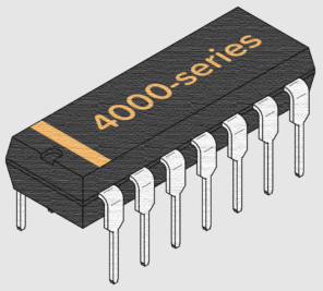
4000 Series CMOS Integrated Circuits
Supply Voltage
4000 series CMOS ICs are crafted to operate within a supply voltage range of 3 to 15V, demonstrating a remarkable ability to endure minor voltage fluctuations. This flexibility enhances their suitability for diverse applications, empowering you to apply them across various environments with ease. Their steadfastness in unpredictable conditions reflects common scenarios where power supply variations can occur.
Input Impedance and Signal Integrity
These ICs exhibit high input impedance, which is beneficial for reducing interference with connected circuits and averting signal deterioration. However, unconnected inputs may encounter electrical noise, possibly resulting in disruptions. Connecting unused inputs to power or ground is advised to maintain performance consistency, a method widely endorsed by circuit specialists based on observations of noise complications.
Output Functionality and Component Compatibility
CMOS ICs in this series can drive around 1mA for typical digital circuit CMOS inputs. When supplied with higher voltages, their output capacity increases to 10mA, offering you the flexibility to incorporate additional components with less effort. For managing larger loads, using an external transistor is a favored approach. A single IC can control up to 50 inputs, showcasing its effectiveness and scalability in extensive projects. In practical applications, cascading multiple ICs optimizes signal transmission with minimal loss.
Signal Transmission and Frequency Range
Signal propagation delay in these ICs is approximately 30ns at a 9V power supply, suitable for many applications but potentially restrictive in high-speed settings, where the 74 series may be more favorable. Their frequency capacity of up to 1MHz supports adequate performance for typical tasks, though intricate operations might require faster alternatives. Practical trials have demonstrated their frequency adaptability.
Energy Consumption Patterns
The 4000 series features minimal power consumption, an attractive attribute for power-sensitive applications. Although power usage does increase with frequency, it stays significantly lower than similar technologies. This trait facilitates sustainable operations, aligning with larger industry trends towards energy efficiency, as seen in numerous development initiatives aimed at reducing ecological impact.
Interweaving Distinct Logic Families
Embracing uniformity in a circuit's logic family fosters consistency and ease. Nevertheless, intertwining varying families is achievable, especially when their power demands synchronize harmoniously. Consider the scenario of integrating the 4000 series with the 74HC family; it’s dynamic to confirm that the power source voltage spans from 3 to 6 volts. Deviations from this range risk yielding errant logic levels or possible failure of components.
Exploring deeper into the distinctions of power supply characteristics highlights their influence on achieving seamless integration. The 74LS family, for example, thrives with a steadfast 5V supply. This subtle but remarkable difference affects component choices deeply, as mismatched voltages can cause lackluster circuit efficiency or component damage. You can tend to keep power stability in your sights, striving to sidestep unexpected circuit malfunctions, illuminating the intricacies of meticulous power management in mixed-family circuits.
To connect a 74LS output with a 4000 or 74HC input reliably employ a 2.2kohm “pull-up” resistor. This component guarantees a sufficiently high input level, steering clear of ill-defined states. Place this pull-up resistor strategically—a technique often used to stabilize logic levels across differing technology landscapes. Its understated presence speaks to how minor alterations can significantly shore up system stability.

Functionalities of Quad 2-Input Logic Gates
In the world of digital electronics, quad 2-input gates hold a place of notable engagement, catering to diverse logic design landscapes. These gates manifest in various configurations, empowering you with the freedom to choose precisely the right fit for their unique applications infused with practical intelligence and a touch of worldly understanding. Let us explore several distinguished types:
• 4001: Quad 2-Input NOR Gate
This gate forms the keystone for implementing initial logical operations, often embraced in circumstances where a logic level's inversion or a basic NOR function brings simplicity and efficiency.
• 4011: Quad 2-Input NAND Gate
Famous for its universal nature, the NAND gate can be ingeniously combined to fashion any ultimate gate type, enhancing the creative processes involved in designing intricate circuits with limited resources.
• 4030: Quad 2-Input EX-OR Gate (obsolete now)
Once a staple in exclusive-OR tasks, the 4030 has gradually been succeeded by more contemporary solutions as logic gate technology strides forward with swiftness and efficacy.
• 4070: Quad 2-Input EX-OR Gate
The contemporary design of this gate remains used in generating and verifying parity within error-checking frameworks, a thoughtful feature active to digital communication systems' integrity.
• 4071: Quad 2-Input OR Gate
This gate seamlessly integrates into scenarios demanding an output upon any input's elevation, an elegant simplicity treasured in systems invoking straightforward OR logic.
• 4077: Quad 2-Input EX-NOR Gate
As the EX-OR gate's complement, the EX-NOR gate plays a key role in digital comparators and equality assessments, preserving the accuracy and fluidity of logical operations.
• 4081: Quad 2-Input AND Gate
When a function bids for high outputs upon dual high inputs, this gate reliably stands as a trusted companion, consistently performing in myriad digital environments.
• 4093: Specialized Quad 2-Input NAND Gate with Schmitt Trigger Inputs
Uniquely characterized by Schmitt trigger inputs, the 4093 adeptly processes signals vulnerable to noise or sluggish transitions. This gate shines through its adept noise resilience and faithful performance amidst challenging circumstances. The integration of hysteresis, growing with higher voltage supplies from approximately 0.5V at a 4.5V baseline, confers advantages when seeking dependable signal stability in fluid surroundings.

Triple 3-Input Gate Logic ICs in Action
Triple 3-input gates provide diverse possibilities for crafting elaborate electronic designs. Each type of gate fulfills a distinct role, embedding your curiosity and desire for innovation:
• 4023: Triple 3-Input NAND Gate
The 4023 gate adeptly handles logical product operations with subsequent inversion. Its ability to manage multiple input signals with ease simplifies circuit frameworks. Inspired by a passion for creativity, you can frequently leverage NAND as a universal gate, crafting inventive solutions and reducing circuit complexity.
• 4025: Triple 3-Input NOR Gate
The 4025 gate is proficient in executing logical sum operations and then inverting the results. It proves advantageous in contexts needing complete negation, allowing you to streamline circuits. This gate's application often results from the drive to optimize resources by reducing the number of physical components required for specific tasks.
• 4073: Triple 3-Input AND Gate
The 4073 gate offers a direct way to achieve logical conjunctions with high accuracy. Basic in demanding environments like safety systems, this gate satisfies the longing for precision in control systems, ensuring processes operate smoothly when all criteria are met.
• 4075: Triple 3-Input OR Gate
The 4075 gate supports logical disjunction effectively, serving as a crucial component in maintaining signal integrity. The implementation of OR gates in industry settings often fuels the pursuit of operational efficiency and responsiveness, reducing downtime and enhancing system control.
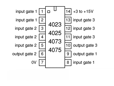
The specialized arrangement accomplished by extending the gate across the package reflects a strategic choice in maximizing spatial utility. This approach allows a more compact assembly on circuit boards, driven by the aspiration to reduce parasitic elements and improve overall electronic performance.
Complex Interactions of Dual 4-Input Gates
In the world of modern electronics, dual 4-input gates play a key role as building blocks in circuit design. These components, known for their versatility, contribute significantly to diverse applications by facilitating logical operations and addressing both intricate and straightforward technical challenges.
• Dual 4-Input NOR Gate (4002)
The dual 4-input NOR gate, identified as 4002, executes a logical NOR operation. It produces a high output solely when each input is low, aligning perfectly with scenarios demanding a fail-safe mechanism. Picture alarm systems, where activation triggers only in the full absence of inputs, affirming the necessity for such a response. The reliability and simplicity of the 4002 make it a go-to choice for you valuing contingency-driven designs in dangerous setups.
• Dual 4-Input NAND Gate (4012)
Functioning as a universal gate, the dual 4-input NAND gate (4012) outputs a low signal when all inputs are high. Its adaptability is unrivaled, as it can replicate multiple logical functions through input reconfiguration. This flexibility finds favor in the construction of sophisticated digital systems, especially when efficiency and minimalism in component usage are priorities. Employing the 4012 thus aids in refining circuit designs while optimizing resource deployment.
• Dual 4-Input OR Gate (4072)
A specialist in detecting any active input, the dual 4-input OR gate (4072) generates a high output if at least one input is high. This feature holds importance in decision-making circuits, where the occurrence of a positive cue prompts consequential actions like enabling backup protocols in computing setups. The 4072 enhances system agility and reliability by promptly acknowledging input presence and ushering in ensuing processes.
• Dual 4-Input AND Gate (4082)
In stark contrast, the dual 4-input AND gate (4082) demands all inputs to be high for a high output. Such a requirement is pivotal in contexts where every condition must be fulfilled before proceeding, typically in safety interlock activation within industrial equipment. The straightforward yet requisite function of the 4082 arms engineers with the ability to exert robust control, ensuring precision in gating is maintained to uphold system integrity.

Within these circuits, the designation "NC" stands for non-connected pins. Grasping the correct management of these pins is used to thwart unintended disturbances in circuit performance. Documenting and verifying each unconnected pin during the design phase is requisite to prevent them from inadvertently becoming origins of noise or unintended signals, thereby preserving the stability and efficacy of the circuit.
4068 NAND/AND Gate IC
The 4068 8-input NAND/AND gate exhibits a unique proficiency in handling an array of inputs simultaneously, characterized by its eight distinctive input ports. Although its propagation delay can pose limitations for high-frequency applications, it is mainly suited to scenarios where swift operation is not the driving factor. This aspect is worth noting in environments where timing accuracy holds notable weight.
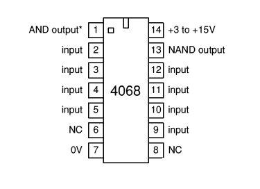
This gate's relatively slower propagation speed makes it advantageous in situations where operational pace is secondary. Such contexts may include educational environments focused on comprehending logical operations rather than executing them at maximum velocity. In practice, the 4068 gate facilitates a lucid demonstration of intricate logic functions without the pressing demand for speedy data processing.
Analysis of the 4069 Hex NOT Gate

The versatility of 4049 NOT and 4050 Buffer Logic Chips
The 4049 Hex NOT and 4050 Hex Buffer integrated circuits (ICs) are recognized for how they manage input voltages as high as +15V, even when powered by a substantially lower supply voltage. This attribute shines mainly in systems where different voltage levels coexist, allowing for seamless interaction among diverse logic families.
These ICs are crafted to efficiently drive the 74LS series inputs, which operate best with a constant +5V supply. This allows for up to four direct connections to 74LS inputs, streamlining circuit design by lessening the need for extra buffering. The avoided mismatches between components are an understated yet valuable feature, adding depth to the design's reliability.

During the implementation of these buffer ICs, pins marked as "NC" should be deliberately left unconnected, indicating that these pins have no linkage to the internal circuitry. This consideration is key during the design process, averting any potential disruption to the IC's normal function. A thorough understanding of these connections facilitates smooth integration into broader systems, highlighting the necessity of detail-oriented installation practices.
4000 Dual 3-Input NOR Gate Configurations
The innovative structure of the 4000 series integrated circuit includes not only a pair of versatile 3-input NOR gates but also a singular NOT gate. These components collectively facilitate a broad range of logic operations, contained neatly within one package. The presence of each "NC" pin ensures non-functional connections are easily identified, aiding in precise configuration.

The design of this IC encourages a smooth and efficient process for constructing intricate logic circuits. You can value its dual 3-input NOR gates, which enable numerous logical functions to be achieved with just this one component, fitting perfectly into compact circuit designs. The integration of a NOT gate enhances its adaptability, allowing for complex combinations that could be cumbersome with separate elements. For example, logical expressions such as (A NOR B OR C) are straightforward to execute with this setup.
4017 Decade Counter
The 4017-decade counter serves as a complex logic component renowned for its applications in digital electronics, facilitating the systematic sequencing of outputs. Leveraging the rising edge of the clock signal, it sequentially transitions outputs from Q0 to Q9 to a high state. With inputs and connections providing flexibility, it affords various practical applications and refined control mechanisms.
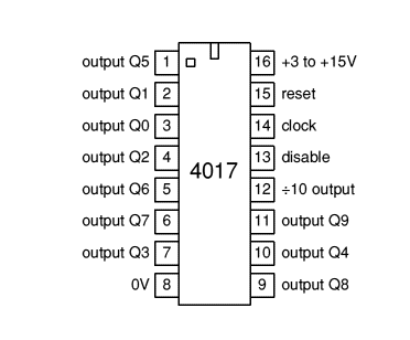
Driven deeply by clock pulses, the 4017 counter advances the count with each transition from low to high. You can utilize this characteristic to create timing sequences or establish ordered actions within circuits. Many find the integration of these principles into designs simplifies processes, introducing an element of structured sophistication to otherwise potentially chaotic signal environments.
Reset Function and Control
Activating the reset function with a high signal ensures the count resets to zero, establishing consistent starting points across cycles. When the reset remains low, the counter retains the current count, providing stability throughout the operational phases. You can propose looping the final count back to the reset input to create a custom counting range, a technique appreciated in applications with specific count constraints.
Disable Input and Inhibition
To interrupt the counting process, a high signal to the disable input effectively pauses sequencing. This feature proves advantageous in situations demanding precise control over operation timing. You can often incorporate this into larger control systems, ensuring operations advance only when conditions are optimal, thereby reflecting an enhanced command of circuit behavior.
÷10 Output and Expanded Uses
With the ÷10 output cycling every five counts, the input frequency is divided by ten, a utility in cascading multiple 4017 counters for extended sequences. This approach benefits systems requiring a decimal expansion of counting capability, where each successive counter accommodates a broader numeral scope. Insights from you emphasize the modularity of this configuration, promoting expansion without losing precision in control.
4026 Counter and Display Driver
The 4026-decade counter, a substantial element in digital electronics, seamlessly orchestrates numerical displays. It operates with a rising clock input, igniting segments a-g on a 7-segment display to mirror the current count, evoking the meticulous attention to detail seen in traditional artistry. Digital clocks and counters frequently depend on their consistent and effective functionality.

Upon receiving a clock pulse, the 4026 progresses the count, converting this digital signal into the illumination of specific segments on the display. When the enable input is set high, the information is continuously refreshed, offering an unfaltering depiction on the display, reminiscent of the careful maintenance of vintage clocks that preserves temporal accuracy.
You can enjoy the flexibility of resetting the count or disabling the counting function through means akin to those utilized in the 4017 counters. This ability to execute periodic resets is dominant in dynamic settings that require routine calibration to zero, similar to checkpoints in a marathon that aid in precise time management and performance analysis. The seamless integration of such resets emphasizes the counter's versatility.
The ÷10 output of the 4026 extends the counting capacity beyond a single digit, facilitating the cascading of additional counters to construct intricate numerical systems. This capacity for expansion mirrors the evolutionary journey of numerical systems in history, where evolving from basic units to complex and higher-order counting supported a myriad of advancements, from early commerce to sophisticated modern computing.
4029 Counter with Preset Capability
The 4029 integrated circuit excels as a synchronous counter, aligning output transitions seamlessly with the clock pulse to avert erroneous glitches. This ability ensures precision in digital circuits, mostly those with timing applications. It offers dual functionality with up and down counting, enhancing design flexibility. The up/down feature directs the counting direction with a high signal for incrementing counts and a low signal for decrementing. Handling the direction input during the clock pulse's high phase is required to guarantee smooth operations and minimize potential errors.

The 4029 counters can be initialized to a specific value by using binary-coded pins alongside a high signal on the preset input. This adds value in scenarios requiring immediate counter adjustment, like synchronizing with an external event or reinstating operations at a known state. This feature sees frequent use when precise interval measurements are domineering. The ease of presetting counters broadens its application in systems, from straightforward digital clocks to intricate computing mechanisms.
4510 Up/Down Decade Counter and 4516 Up/Down 4-Bit Counter
The synchronous 4510 and 4516 counters, similar to the 4029 model, exhibit an unparalleled capacity for error-free performance. Directional consistency and resetting are managed via specific inputs, ensuring homogeneous operations. Moreover, for the presetting feature to function harmoniously, it is required for the clock input to maintain a low state to achieve synchronization.

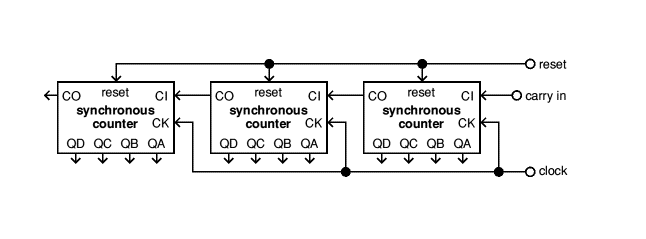
Establishing Synchronous Counter Networks
To form an interconnected network of counters, synchronize them meticulously by configuring their clock inputs together and channeling the carry-out from one counter directly into the carry-in of the next. In the 4029, 4510, and 4516 models, holding the initial counter's carry-in at a low state is a must, facilitating accurate signal travel throughout the network. This setup can be likened to conducting an orchestra, where each component contributes in harmony, elevating stability in practical circuit designs. It simultaneously emphasizes the reliability of these devices within intricate digital systems.
Effectively arranging a sequence of counters in applications involves precision in managing the carry-chain links to prevent errors such as missed or duplicate counts. This task embodies meticulous preparation and strategic forethought, offering profound insights into problem-solving and highlighting the importance of attention to detail. Additionally, reflecting upon the effects of a well-structured setup may provide valuable guidance for enhancing the overall efficiency of systems, thus cultivating a richer understanding of the complexities in digital design.
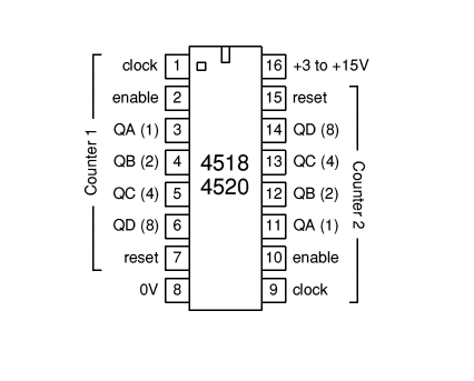
Comparing the 4518 and 4520 Counter ICs
The 4518 and 4520 integrated circuits are engineered with dual parallel counters, each advancing synchronously with the rising edge of a clock signal. These circuits offer the functionality to be reset to zero through designated inputs. For applications necessitating counts below their inherent maximum limit, an appropriate output must be rerouted to the reset input. This method finds relevance in diverse practical applications, mostly within the domain of frequency division and digital clock systems.
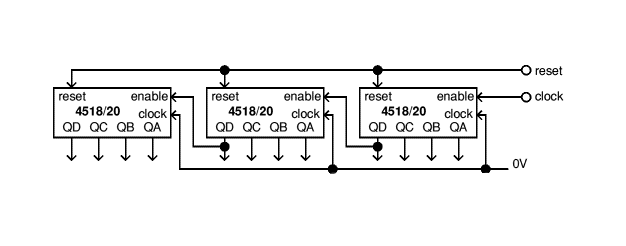
Serial Configuration Techniques for 4518 and 4520
To create an expansive count cycle, one needs to ensure the clock inputs are maintained in a low state while the enable inputs are activated. By serially connecting the counters' outputs, a cascading or ripple effect arises, emulating intricate counting sequences. However, for utmost precision in environments where timing is serious, such as digital signal processing systems, incorporating logic gates is beneficial for exact synchronous counting. This approach exemplifies the importance of timing precision and stands as a testament to the intricate dance between electronics and timing.
Overview of the 4020 14-Bit Ripple Counter
Ripple counters function through a series of interconnected flip-flops, where the output of one flip-flop provides the timing for the next in the sequence. In the specific case of the 4020 14-bit counter, each bit corresponds to a power of two, which allows for division by 16,384 across all stages. One notable aspect of these counters is their counting sequence progresses at the falling edge of the input clock signal, demonstrating their unique operational principle.
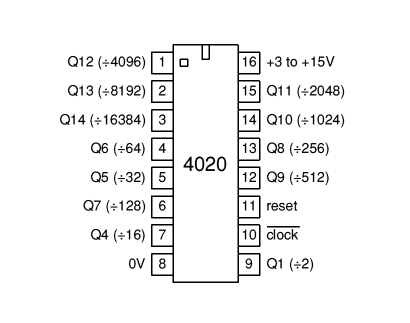
The output stages of a ripple counter such as the 4020 are organized to represent progressively higher powers of two. For instance, Qn signifies the value of 2^n. To clear or reset the counter, a particular high input is applied, setting all flip-flops to a predetermined initial state. Success in digital design often involves implementing effective reset mechanisms, ensuring that synchronization is achieved throughout the digital system.
Ripple counters, while simple in design, may introduce challenges due to their inherent propagation delays, potentially causing undesirable logic discrepancies. When an earlier flip-flop changes state, there is a brief delay before this transition is observed in the subsequent flip-flop, which could transiently affect the integrity of connected digital circuits. You can draw from a wealth of experience, often deploy additional synchronization techniques, or opt for alternatives, such as synchronous counters, to address and remedy these potential issues.
4024 Ripple Counter in Digital Timing
The 4024 responds to each clock edge by rippling through its states, much like the 4020, with outputs reflecting sequential powers of two. This architecture provides a streamlined method for representing states within its 7-bit register. Typically, these counters are employed in scenarios demanding accurate timing and frequency division, such as digital clocks or signal processing systems. You can frequently focus on meticulous clock signal management to prevent any glitches, thereby assuring that transitions remain smooth and predictable. This practice not only reflects technical prowess but also mirrors a deep-seated desire for stability and control.
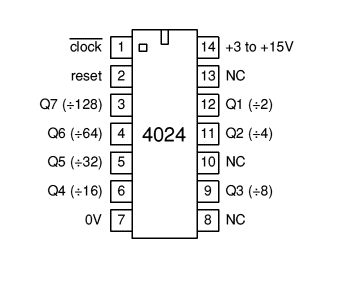
The reset function, similar to that of the 4020, can be activated to instantly return the counter to its initial state. Within the dynamic field of digital circuit design, having a dependable reset option is highly valued, especially during power-up phases or troubleshooting sessions. You can often incorporate reset controls into broader circuit systems, facilitating a controlled restart or enabling synchronization across interconnected modules.
4040 12-Bit Ripple Counter IC
The 4040 12-bit ripple counter operates through clock input and reset functions similar to those found in the 4020 counters. It employs a series of flip-flops to perform its counting functions, incrementing through powers of two. Digging into the mechanics of the 4040 allows one to appreciate its extensive applications in digital circuits, whether it's for frequency tracking or division.

The basic operation of the 4040-ripple counter is straightforward and effective. Each flip-flop in the chain divides the frequency of the input signal by two. As a frequency divider, the counter produces a diverse set of divided frequencies, catering to a variety of applications. These features become mostly advantageous in settings where precise timing signals are sought. For example, when crafting digital clocks or timing devices, controlling exact time intervals or sequences is dynamic and links directly to the dependability of the 4040.
4060 14-Bit Ripple Counter with Built-in Oscillator
The 4060-ripple counter is an active component in digital logic systems, designed to sequentially count the occurrences of input signals. Its utility extends across various applications due to its ability to generate divided clock frequencies. However, one dangerous consideration is that interfacing its outputs with logic gates may introduce temporary glitches. These glitches occur because of the inherent delay in how the counter's outputs respond to a clock pulse, a characteristic of ripple counters.
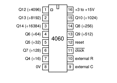
Ripple counters like the 4060 operate on the falling edge of the clock signal, meaning that the signal's transition from high to low initiates the counting process. Each output, labeled as Qn, corresponds to a binary count stage. The value of each output is determined by the formula Qn = 2n, where the nth stage divides the clock frequency by 2n. For example, the output Q4 divides the clock frequency by 16, while the output Q14 divides it by 16,384. Importantly, in the 4060 model, certain outputs—specifically Q1 to Q3 and Q11—are inactive and cannot be used.

The reset input is another key feature. To ensure smooth counting, keep the reset input in a low state. Setting the reset input high will immediately zero out the count, causing all outputs to go low and restarting the process from the beginning. This functionality is useful in applications where a resettable counter is required. One of the defining features of the 4060 is its internal oscillator, which supports three distinct configuration options for generating the clock signal. These options allow for flexibility in meeting specific application requirements. Below are the three configurations:
• External Clock Source: The 4060 can be operated using an external clock source. In this configuration, the clock signal is directly fed into the counter's clock input pin. When using an external clock, pins 9 and 10, which are reserved for oscillator components, are bypassed. This setup provides users with a straightforward means of integrating the 4060 into systems where an existing clock source is available.
• RC Oscillator Configuration: An RC oscillator can be connected to the 4060 to generate the clock signal. This setup requires an external resistor (R) and capacitor (C) to determine the frequency of oscillation. The frequency is approximately calculated as:
f ≈ 1 / (2 × R1 × C)
To ensure stable operation, it is recommended to follow these guidelines. R1 should be at least 50 kΩ, with R2 (optional) being 2–10 times the value of R1. The RC oscillator's performance is sensitive to supply voltage variations, so voltage stability is crucial, particularly when operating below 7V.
• Crystal Oscillator Setup: For applications requiring high precision, a crystal oscillator can be used. A typical example is the use of a 32,768 Hz crystal, which produces a highly accurate 2 Hz output at Q14. In this setup. Pin 9 is unused, simplifying the circuit. The crystal oscillator ensures reliable and stable frequency generation, making it ideal for timing and clocking applications.
BCD to Decimal Decoder
BCD to decimal decoders frequently appear in varied digital applications serving distinct purposes. They operate by receiving a Binary-Coded Decimal (BCD) input and faithfully converting it into a corresponding decimal output. In actual situations, if an invalid BCD input is encountered, the output will default to a low state, ensuring the dependability of digital systems by minimizing erroneous results. Such features aid you in achieving accuracy and precision in your digital circuit creations.

Each decoder incorporates logic gates that interrelate every 4-bit BCD input to a unique decimal outcome. This design supports the operation of components needing decimal display or processing. For example, digital clocks and calculators employ such decoders to transform BCD-coded time or numerical inputs into a format easily comprehensible by interfaces. Your insights stress the significance of meticulously crafting the decoding logic for smooth integration in expansive systems. Thorough initial planning can significantly ease this process.
Within the domain of consumer electronics, BCD to decimal decoders facilitates effective data display on LED or LCD panels. This particular application emphasizes the practical need to convert binary data into accessible information. Confronting your interface obstacles frequently involves refining the decoder circuit to decrease power consumption and maintain responsiveness. Striking such a balance not only boosts performance but also enriches your satisfaction.
4511 BCD to 7-Segment Display Driver
The ability to convert Binary Decimal (BCD) inputs into a 7-segment display output holds various applications in electronics. The 4511-driver chip plays a dominant role in this process, specifically crafted to illuminate the segments of a common cathode 7-segment display based on BCD input signals. Digging into this conversion process not only enriches technical understanding but also casts light on its practical uses in everyday devices.

The 4511 chip acts as a bridge between digital input and visual output systems, translating BCD values into distinct display segments. It finds its place in scenarios where numerical displays, like digital clocks and electronic meters, are basic, and in instances where storing and retrieving settings can significantly influence performance. Proficiency in handling the 4511's pin configuration and understanding its logic are key, as are skills in soldering and circuit design, which greatly enhance practical application.
Utilizing a common cathode-type display with the 4511 driver chip aligns with the electrical traits of display units. This approach involves grounding each segment through a unified cathode connection, facilitating individual segment control through the 4511’s outputs. Such compatibility emphasizes the merit of grasping component specifications, with practical insights emphasizing how effective power management extends component lifespan.
Programming the correct BCD codes during conversion to 7-segment displays is the ultimate to outputting desired numeric. Testing various inputs for precision accentuates the necessity of accuracy in this technical undertaking. Furthermore, settings for storage flexibility allow for adjustments or changes in display needs over time, thereby enhancing adaptability in environments that demand dynamic changes.
About us
ALLELCO LIMITED
Read more
Quick inquiry
Please send an inquiry, we will respond immediately.
Frequently Asked Questions [FAQ]
1. How is the 7400 series logic different from the 4000 series?
The 74HC series operates within a limited voltage range, with a maximum supply voltage of 6V. In contrast, the CD4000 series supports higher voltages, up to 18V, making it more suitable for battery-powered systems and designs requiring a wider voltage tolerance.
2. What is the operating voltage range of the 4000 series?
The CD4000 series operates between 3V and 15V.
3. What does CMOS stand for in ICs?
CMOS stands for Complementary Metal-Oxide Semiconductor, a leading semiconductor technology used in most modern integrated circuits (ICs), including chips and microchips. It is based on MOSFET (metal-oxide-semiconductor field-effect transistor) principles.
4. What is CMOS technology used for?
CMOS technology is used to build integrated circuits (ICs), such as microprocessors, microcontrollers, memory chips (like CMOS BIOS), and various digital logic circuits.
LM7905 Voltage Regulator: Features, Equivalents, and Pinout
on November 29th
Instrumentation Amplifiers: Types, Applications, and Advantages
on November 29th
Popular Posts
-

Complex Instruction Set Computers: How They Changed Computing?
on April 18th 147749
-

USB-C Pinout and Features
on April 18th 111920
-

Using Xilinx Unified Simulation Primitives: A Comprehensive Guide to FPGA Design and Simulation
on April 18th 111349
-

Power Supply Voltages in Electronics: Meaning of VCC, VDD, VEE, VSS, and GND
on April 18th 83714
-

RJ45 Connector Guide: Pinout, Wiring, Cable Types, and Uses
on January 1th 79502
-

The Ultimate Guide to Wire Color Codes in Modern Electrical Systems
The way our electrical systems use colors isn’t just for looks. Each wire color now indicates a specific function, making it easier to identify and handle electrical components correctly during ins...on January 1th 66872
-

Quality (Q) Factor: Equations and Applications
The quality factor, or 'Q', is important when checking how well inductors and resonators work in electronic systems that use radio frequencies (RF). 'Q' measures how well a circuit minimizes energy...on January 1th 63005
-

Purge Valve Guide: Function, Symptoms, Testing, and Replacement for Optimal Engine Performance
The purge valve is a key part of a car’s system that helps keep the air clean by managing fuel vapors before they can escape into the atmosphere. This not only helps the environment by reducing pol...on January 1th 62951
-

Achieving Peak Performance with the Maximum Power Transfer Theorem
The Maximum Power Transfer Theorem explains how energy from a source, such as a battery or generator, flows to a connected load. It shows the exact condition where the load receives the most power....on January 1th 54078
-

A23 Battery Specifications and Compatibility
The A23 battery is a small, cylinder-shaped battery with high voltage. Also called 23A, 23AE, or MN21, it runs at 12 volts and much higher than AA or AAA batteries. Its special design make...on January 1th 52092
HOT Part Number
-

BD9B100MUV-E2
Rohm Semiconductor
IC REG BUCK ADJ 1A 16VQFN
UPD70F3539AF5A9-PN7-Q-A
Renesas Electronics America Inc
IC MICROCONTROLLER
18081A621JAT2A
KYOCERA AVX
CAP CER 620PF 100V NP0 1808
FDN340P
onsemi
MOSFET P-CH 20V 2A SUPERSOT3
70231-101
Amphenol ICC (FCI)
CONN RCPT BLADE PWR 8POS EDGE MT
MPSW42RLRAG
onsemi
TRANS NPN 300V 0.5A TO92
MC7824BT
onsemi
IC REG LINEAR 24V 1A TO220AB
AD8009ARZ-REEL
Analog Devices Inc.
IC OPAMP CFA 1 CIRCUIT 8SOIC
LT1815CS5#TRPBF
Analog Devices Inc.
IC OPAMP VFB 1 CIRCUIT TSOT23-5
DG411DYZ
Renesas Electronics America Inc
IC SWITCH SPST-NCX4 35OHM 16SOIC
VFT2060C-M3/4W
Vishay General Semiconductor - Diodes Division
DIODE SCHOTTKY 20A 60V ITO-220AB
TSX562AIYST
STMicroelectronics
IC CMOS 2 CIRCUIT 8MINISO
MR256D08BMA45
Everspin Technologies Inc.
IC RAM 256KBIT PARALLEL 48FBGA
VSC3312YYP-01
Microchip Technology
IC SWITCH 16X16 6.5GBPS 196FCBGA
XC68HC908GP20CFB
Motorola
TSG 8BIT20K FLASH
CSR8811A08-ICXR-R
Qualcomm
IC RF TXRX+MCU BLUETOOTH
MPSW05
onsemi
TRANS NPN 60V 0.5A TO92
1N4055R
Solid State Inc.
DIODE GEN PURP REV 900V 275A DO9 -

ASX342ATSC00XPED0-DP
onsemi
IMAGE SENSOR VGA 1/4 CIS SOC
0433.125NR
Littelfuse Inc.
FUSE BOARD MNT 125MA 125VAC/VDC
1SMA5941BT3G
onsemi
DIODE ZENER 47V 1.5W SMA
DCP010512BP-U/700
Texas Instruments
DC DC CONVERTER 12V 1W
1-1734344-1
TE Connectivity AMP Connectors
CONN D-SUB HD RCPT 15P R/A SLDR
KSD1621STF
onsemi
TRANS NPN 25V 2A SOT89-3
BQ24161RGET
Texas Instruments
IC BATT CHG LI-ION 1CELL 24VQFN
BTA26-600BW
STMicroelectronics
TRIAC ALTERNISTOR 600V 25A TOP3
NCP1239DD65R2G
onsemi
IC OFFLINE SWITCH FLYBACK 7SOIC
TMS320TCI6482BZTZA
Texas Instruments
TMS320 - DIGITAL SIGNAL PROCESSO
BQ20Z90DBTR-V150
Texas Instruments
IC GAS GAUGE LI-ION 30TSSOP
PCMB104T-1R0MT
Susumu
FIXED IND 1UH 18A 3.3 MOHM SMD
CY29942AXCT
Infineon Technologies
IC CLK BUFFER 1:18 200MHZ 32TQFP
CC0402KRX7R9BB561
YAGEO
CAP CER 560PF 50V X7R 0402
STPS20M60SG-TR
STMicroelectronics
DIODE SCHOTTKY 60V 20A D2PAK
AT25010N-10SC-2.7
Microchip Technology
IC EEPROM 1KBIT SPI 3MHZ 8SOIC
04023A1R0CAT4A
KYOCERA AVX
CAP CER 1PF 25V C0G/NP0 0402
ISL6327IRZ
Intersil
SWITCHING CONTROLLER, VOLTAGE-MO -

LQW18AN75NG0ZD
Murata Electronics
FIXED IND
DFA100BA160
SanRex Corporation
DIODE MODULE 1600V 100A
BAR46AFILM
STMicroelectronics
DIODE ARRAY SCHOTTKY 100V SOT23
MAX825SEUK
Analog Devices Inc./Maxim Integrated
IC SUPERVISOR MPU
MMST2222A-7-F
Diodes Incorporated
TRANS NPN 40V 0.6A SOT323
FODM8801AR2
onsemi
OPTOISO 3.75KV TRANS 4-MINI-FLAT
FJV1845FMTF
Fairchild Semiconductor
SMALL SIGNAL BIPOLAR TRANSISTOR,
EVK105RH5R1JW-F
Taiyo Yuden
CAP CER 5.1PF 16V R2H 0402
6651170-3
TE Connectivity AMP Connectors
CONN EDGE DUAL FMALE 4POS 0.508
KSZ8893FQLI-FX
Microchip Technology
IC SWITCH ETH 3PORT 128QFP
170M6340
Eaton - Bussmann Electrical Division
FUSE SQUARE 400A 1.3KVAC RECT
BCM20741A2KFB1G
Broadcom Limited
SINGLE-CHIP BLUETOOTH
MAX3443EASA+
Analog Devices Inc./Maxim Integrated
IC TRANSCEIVER HALF 1/1 8SOIC
GRM0335C1H9R3DA01D
Murata Electronics
CAP CER 9.3PF 50V C0G/NP0 0201
TNY175PN
Power Integrations
11.5 W (85-265 VAC) 15 W (230 VA
742700726
Würth Elektronik
FERRITE CORE 278 OHM SOLID 4MM
DM74S20N
onsemi
IC GATE NAND 2CH 4-INP 14DIP
P4SMA56CA-E3/61
Vishay General Semiconductor - Diodes Division
TVS DIODE 47.8VWM 77VC DO214AC