Understanding Reactive Power: How It Works and Why It Matters
Reactive power is a key part of AC electrical systems because it supports the electric and magnetic fields that many devices need to operate. This article explains what reactive power is, how it works in AC circuits, and how it is calculated using voltage, current, and power factor. It also examines how reactive power behaves in resistive, inductive, capacitive, and nonlinear loads. In addition, it covers the benefits of proper reactive power management, its practical applications, and its role in modern power systems.Catalog
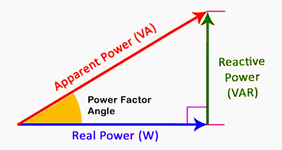
Figure 1. Reactive Power Triangle
What Is Reactive Power?
Reactive power is the portion of electrical power in an AC system that does not perform useful work but is necessary to sustain electric and magnetic fields. It exists because voltage and current are not perfectly aligned in time, creating a phase difference between them. This phase shift causes energy to move back and forth between the source and reactive components instead of being fully consumed. Reactive power is important for operating equipment like motors, transformers, and inductive devices in power systems. It plays a key role in maintaining voltage levels and ensuring stable system operation. Without reactive power, many AC electrical systems would not function properly or efficiently.
How Reactive Power Works in AC Circuits?
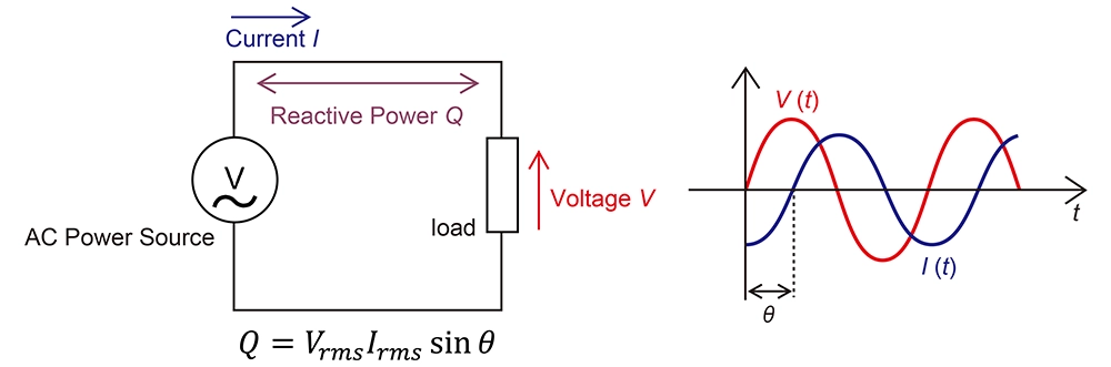
Figure 2. Reactive Power in AC Waveforms and Circuit
Reactive power in AC circuits arises when voltage and current do not reach their peaks at the same time. This phase difference creates a situation where energy is temporarily stored and then returned to the power source instead of being continuously used. As the alternating current changes direction, energy moves into and out of the electric or magnetic fields within the circuit. This continuous exchange results in a cyclic flow of energy rather than a one-way transfer.
The shifting relationship between voltage and current can be observed through their waveforms, where one waveform leads or lags the other. This timing difference is what produces reactive power in the system. Even though this energy does not perform useful work, it is still required to support the operation of many electrical devices. The presence of this phase shift directly influences how power flows within the circuit.
Reactive Power Calculation
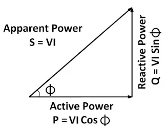
Figure 3. Power Triangle and Equations
First, identify the given values. Start by listing what you already know:
• Voltage (V) = 230 V
• Current (I) = 10 A
• Power factor (cos φ) = 0.8 (lagging)
These values define the operating condition of the circuit.
Next, calculate the apparent power (S). Apparent power represents the total power supplied by the source.
• S = V × I = 230 × 10 = 2300 VA
This is the full power demand before separating useful and non-useful components.
Then, calculate the active power (P). Active power is the portion that actually performs useful work.
• P = V × I × cos φ = 230 × 10 × 0.8 = 1840 W
This tells you how much power is effectively used by the load.
Lastly, calculate the reactive power (Q). Reactive power comes from the phase difference and can be found using sin φ.
• sin φ = √(1 − 0.8²) = 0.6
• Q = V × I × sin φ = 230 × 10 × 0.6 = 1380 VAR
This represents the power that circulates between the source and the load. The final results show that the apparent power (S) is 2300 VA, the active power (P) is 1840 W, and the reactive power (Q) is 1380 VAR. These values illustrate how the total supplied power is divided into useful power that performs work and reactive power that supports the system. This clear breakdown makes it easier to understand, analyze, and manage power flow in AC electrical systems.
How Reactive Power Interacts with Different Load Types?
Resistive (Ohmic) Loads
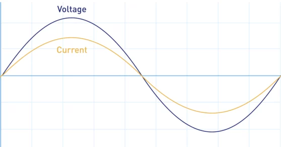
Figure 4. Voltage and Current In Phase
Resistive loads are electrical components that consume energy directly without storing it in electric or magnetic fields. In these loads, voltage and current rise and fall at the same time, meaning there is no phase difference between them. Because both waveforms are perfectly aligned, all the supplied power is converted into useful work such as heat or light. This alignment can be seen in the overlapping waveforms where peaks and zero crossings match exactly. As a result, there is no energy flowing back to the source during the cycle. This condition means reactive power is essentially zero in purely resistive circuits. Common examples include heaters and incandescent lamps where energy is fully utilized.
Inductive Loads
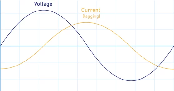
Figure 5. Current Lagging Voltage
Inductive loads are devices that store energy in magnetic fields when current flows through them. In these loads, the current waveform lags behind the voltage waveform due to the nature of magnetic energy storage. This delay creates a phase difference where energy is temporarily held and then returned to the source. The separation between the peaks of voltage and current illustrates this lagging behavior. Because of this phase shift, reactive power is produced and flows within the system. This type of reactive power is considered positive and is common in equipment like motors and transformers. Inductive loads are widely used in industrial and power distribution systems.
Capacitive Loads
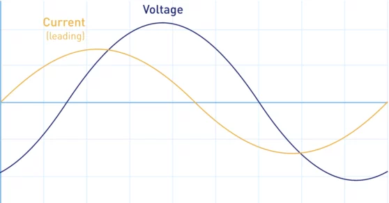
Figure 6. Current Leading Voltage
Capacitive loads are electrical components that store energy in electric fields between conductive plates. In these loads, the current waveform leads the voltage waveform, meaning it reaches its peak before the voltage does. This leading relationship creates a phase difference opposite to that of inductive loads. The waveform pattern shows current advancing ahead of voltage during each cycle. As energy is stored and released in the electric field, reactive power flows in the system. This type of reactive power is considered negative. Capacitive loads are commonly used in power factor correction and voltage regulation applications.
Nonlinear (Harmonic) Loads
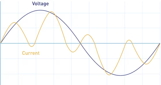
Figure 7. Distorted Current Waveform
Nonlinear loads are devices that draw current in a non-sinusoidal manner even when supplied with a sinusoidal voltage. These loads introduce distortions in the current waveform, creating harmonic components at multiple frequencies. Instead of smooth waveforms, the current appears irregular and uneven compared to the voltage. This distortion affects how reactive power behaves in the system by adding complexity beyond simple phase shifts. The interaction between harmonics and the supply can lead to additional reactive effects. These loads are common in modern electronics such as computers, LED drivers, and switching power supplies. Managing their impact is important for maintaining power quality.
Advantages of Proper Reactive Power Management
• Improves overall energy efficiency
• Maintains stable voltage levels
• Reduces power transmission losses
• Enhances equipment lifespan
• Prevents system overload conditions
• Supports reliable grid operation
Applications of Reactive Power
1. Power Transmission Networks
Reactive power is important in long-distance transmission lines to maintain voltage stability. It helps prevent voltage drops over extended distances. Utilities use compensation devices to regulate reactive power flow. This ensures efficient and reliable electricity delivery.
2. Industrial Manufacturing Systems
Factories rely on reactive power for operating motors and heavy machinery. Proper management prevents inefficiencies in large electrical loads. It helps maintain stable voltage during high demand. This improves production reliability and equipment performance.
3. Renewable Energy Systems
Solar and wind systems require reactive power control for grid integration. It helps stabilize voltage fluctuations caused by variable generation. Inverters are used to manage reactive power output. This ensures compatibility with existing power grids.
4. Electrical Substations
Substations use reactive power compensation to control voltage levels. Devices like capacitors and reactors are installed for regulation. This improves system efficiency and reduces losses. It also supports smooth power distribution.
5. Commercial Buildings
Large buildings use reactive power for HVAC systems and elevators. Proper control improves energy efficiency in daily operations. It reduces unnecessary power consumption. This lowers operational costs and improves reliability.
6. Data Centers and IT Infrastructure
Data centers require stable power for sensitive equipment. Reactive power management helps maintain consistent voltage levels. It prevents disruptions caused by power fluctuations. This ensures continuous and reliable operation.
Reactive Power vs Active Power vs Apparent Power
|
Aspect |
Active Power (W) |
Reactive Power
(VAR) |
Apparent Power
(VA) |
|
Definition |
Useful power
that performs work |
Power that
oscillates between source and load |
Total supplied
power |
|
Function |
Produces output
like heat or motion |
Supports
electric/magnetic fields |
Represents total
demand |
|
Role |
Consumed energy |
Stored and
returned energy |
Combined effect |
|
Unit |
Watts (W) |
Volt-Amp
Reactive (VAR) |
Volt-Ampere (VA) |
|
Energy Use |
Fully utilized |
Not consumed |
Partially
utilized |
|
Direction |
One-way flow |
Back-and-forth
flow |
Combined flow |
|
System Impact |
Drives loads |
Maintains
operation |
Determines
capacity |
|
Dependence |
Load demand |
Phase shift |
Both P and Q |
|
Measurement |
Power meter |
VAR meter |
Apparent meter |
|
Contribution |
Real output |
Support function |
Total
requirement |
|
Efficiency |
Directly affects
efficiency |
Indirect effect |
Indicates system
load |
|
Presence |
Always in
working systems |
Exists with
phase difference |
Always present |
|
Control |
Load-based |
Compensation
devices |
System design |
|
Application |
Appliances,
machines |
Motors,
transformers |
All AC systems |
|
Relationship |
Component of
total power |
Component of
total power |
Combination of
both |
Reactive Power Control in Modern Power Systems
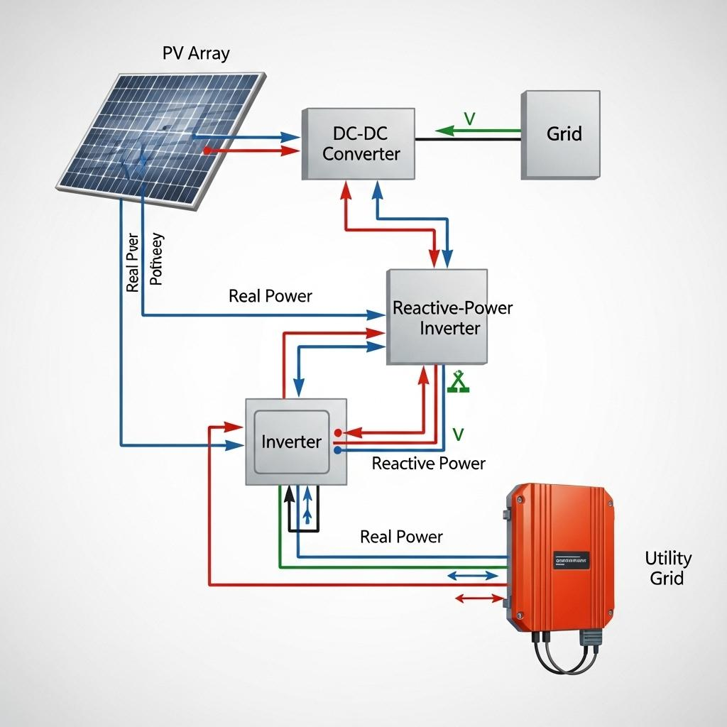
Figure 8. Reactive Power Control Using a Smart Inverter
Reactive power in modern power systems is actively managed through power electronic devices that regulate energy flow between generation sources and the grid. In renewable-based systems, photovoltaic arrays generate real power, which is processed through converters and delivered to the grid via inverters. Alongside real power transfer, reactive power is controlled independently to maintain stable voltage levels and improve power quality. This control allows the system to respond to changing load conditions and prevent voltage fluctuations across the network. By coordinating multiple conversion stages, modern systems ensure that both real and reactive power are delivered efficiently. This approach supports reliable operation, especially in distributed generation environments.
As illustrated in the figure, the smart inverter plays a central role by adjusting reactive power exchange with the utility grid. It can inject or absorb reactive power without affecting the real power generated by the PV array, allowing flexible voltage regulation. The interaction between the inverter, DC-DC converter, and grid ensures continuous monitoring and response to system conditions. This dynamic control helps stabilize the grid during variations in solar generation and load demand. By managing reactive power in real time, smart inverters reduce dependence on traditional compensation devices. This makes them great for maintaining grid stability in modern, renewable-integrated power systems.
Conclusion
Reactive power does not directly perform useful work, but it is good for maintaining voltage, supporting field-based devices, and keeping AC systems stable. Its behavior depends on the relationship between voltage and current, which also determines how power is divided into active, reactive, and apparent components. Different load types affect reactive power in different ways, making proper analysis and control important for efficiency, equipment protection, and power quality. Effective reactive power management supports reliable operation across grids, industrial systems, renewable energy installations, substations, commercial buildings, and data centers.
About us
ALLELCO LIMITED
Read more
Quick inquiry
Please send an inquiry, we will respond immediately.
Frequently Asked Questions [FAQ]
1. Why is reactive power measured in VAR instead of watts?
Reactive power is measured in VAR (volt-ampere reactive) because it represents energy that oscillates between the source and load, not energy consumed. Watts measure real power used for work, while VAR distinguishes non-working power in AC systems.
2. What happens if there is too much reactive power in a system?
Excess reactive power can cause voltage rise, overheating, and reduced system efficiency. It may also overload equipment and lead to instability in power networks if not properly controlled.
3. What happens if reactive power is too low?
Low reactive power can lead to voltage drops, poor equipment performance, and potential system collapse. It makes it harder to maintain stable voltage levels across the electrical network.
4. Can renewable energy systems generate reactive power?
Yes, modern renewable systems like solar inverters and wind turbines can generate or absorb reactive power. This helps stabilize grid voltage and supports integration with existing power systems.
5. How does reactive power impact transmission efficiency?
High reactive power increases current flow, which leads to higher transmission losses. Managing it properly improves efficiency and allows more real power to be delivered to loads.
Why Devices Use AC Adapters
on April 13th

USB-C vs USB PD: Complete Comparison Guide
on April 11th
Popular Posts
-

Complex Instruction Set Computers: How They Changed Computing?
on April 17th 147721
-

USB-C Pinout and Features
on April 17th 111792
-

Using Xilinx Unified Simulation Primitives: A Comprehensive Guide to FPGA Design and Simulation
on April 17th 111328
-

Power Supply Voltages in Electronics: Meaning of VCC, VDD, VEE, VSS, and GND
on April 17th 83653
-

RJ45 Connector Guide: Pinout, Wiring, Cable Types, and Uses
on January 1th 79378
-

The Ultimate Guide to Wire Color Codes in Modern Electrical Systems
The way our electrical systems use colors isn’t just for looks. Each wire color now indicates a specific function, making it easier to identify and handle electrical components correctly during ins...on January 1th 66810
-

Quality (Q) Factor: Equations and Applications
The quality factor, or 'Q', is important when checking how well inductors and resonators work in electronic systems that use radio frequencies (RF). 'Q' measures how well a circuit minimizes energy...on January 1th 62968
-

Purge Valve Guide: Function, Symptoms, Testing, and Replacement for Optimal Engine Performance
The purge valve is a key part of a car’s system that helps keep the air clean by managing fuel vapors before they can escape into the atmosphere. This not only helps the environment by reducing pol...on January 1th 62865
-

Achieving Peak Performance with the Maximum Power Transfer Theorem
The Maximum Power Transfer Theorem explains how energy from a source, such as a battery or generator, flows to a connected load. It shows the exact condition where the load receives the most power....on January 1th 54050
-

A23 Battery Specifications and Compatibility
The A23 battery is a small, cylinder-shaped battery with high voltage. Also called 23A, 23AE, or MN21, it runs at 12 volts and much higher than AA or AAA batteries. Its special design make...on January 1th 52032
HOT Part Number
-

STM6718TGWY6F
STMicroelectronics
IC SUPERVISOR 2 CHANNEL SOT23-5
LMV823IST
STMicroelectronics
IC OPAMP GP 2 CIRCUIT 10MINISO
170M6658
Eaton - Bussmann Electrical Division
FUSE SQUARE 500A 700VAC RECT
CYPD4136-24LQXQT
Infineon Technologies
IC MCD CCG4 WIRED 24QFN
LQH3NPN4R7NJ0L
Murata Electronics
FIXED IND 4.7UH 1.12A 156MOHM SM
74LCX244MSAX
onsemi
IC BUF NON-INVERT 3.6V 20SSOP
MIC4428BMM
Microchip Technology
IC GATE DRVR LOW-SIDE 8MSOP
LTC2165IUK
Analog Devices Inc.
IC ADC 16BIT PIPELINED 48QFN
AOI403
Alpha & Omega Semiconductor Inc.
MOSFET P-CH 30V 15A/70A TO251A
293D106X0016B2TE3
Vishay Sprague
CAP TANT 10UF 20% 16V 1411
ADG3247BCPZ
Analog Devices Inc.
IC BUS SWITCH 8 X 1:1 40LFCSP
LM53600MQDSXTQ1
Texas Instruments
IC REG BUCK ADJ 650MA 10WSON
TPD1E0B04DPLR
Texas Instruments
TVS DIODE 3.6VWM 10.1VC 2X2SON
8121
Keystone Electronics
CBL CLAMP P-TYPE FASTENER
RC2010FK-078R2L
YAGEO
RES 8.2 OHM 1% 3/4W 2010
MB90096PF-G-002-BNDE1
Infineon Technologies
IC ANALOG
RT0402BRE0733KL
YAGEO
RES SMD 33K OHM 0.1% 1/16W 0402
VNS1NV04DTR-E
STMicroelectronics
IC PWR DRIVER N-CHANNEL 1:1 8SO -

TLV2631IDR
Texas Instruments
IC OPAMP GP 1 CIRCUIT 8SOIC
EMK212AB7475MGHT
Taiyo Yuden
CAP CER 4.7UF 16V X7R 0805
CL05B392KB5NNND
Samsung Electro-Mechanics
CAP CER 3900PF 50V X7R 0402
B82793C0105N265
EPCOS - TDK Electronics
CMC 1MH 700MA 2LN SMD AEC-Q200
ADF4360-8BCPZ
Analog Devices Inc.
IC FANOUT DIST 24LFCSP
EN6360QI
Intel
DC DC CONVERTER 0.6-5.8V 46W
FDMC2512SDC
Fairchild Semiconductor
POWER FIELD-EFFECT TRANSISTOR, 3
GRM31M6R1H911JZ01L
Murata Electronics
CAP CER 910PF 50V R2H 1206
IXTK90N15
IXYS
MOSFET N-CH 150V 90A TO264
06032U5R1BAT4A
KYOCERA AVX
CAP CER 5.1PF 200V C0G/NP0 0603
MAX9867EWV+T
Analog Devices Inc./Maxim Integrated
IC STEREO AUD CODEC LP 30WLP
ULQ2003ATPWRQ1
Texas Instruments
IC PWR DRIVER NPN 1:1 16TSSOP
LT1782IS6#TRMPBF
Analog Devices Inc.
IC OPAMP GP 1 CIRCUIT TSOT23-6
MMBZ5229BLT1G
onsemi
DIODE ZENER 4.3V 225MW SOT23-3
CY8C24123A-24SXI
Infineon Technologies
IC MCU 8BIT 4KB FLASH 8SOIC
AD8417WBRMZ
Analog Devices Inc.
IC CURRENT SENSE 1 CIRCUIT 8MSOP
1766501-1
TE Connectivity AMP Connectors
CONN RCPT ATCA 34POS PCB
MIC27600YJL-TR
Microchip Technology
IC REG BUCK ADJUSTABLE 7A 28MLF -
LTC3112IDHD#PBF
Analog Devices Inc.
IC REG BCK BST ADJ 2.5A 16DFN
TPS65982DCZQZR
Texas Instruments
IC REGULATOR CONV SMD
LM45CIM3
Texas Instruments
SENSOR ANALOG -20C-100C SOT23-3
FQPF22P10
onsemi
MOSFET P-CH 100V 13.2A TO220F
5.0SMDJ7.5CA
MDE Semiconductor Inc
TVS DIODE UP 7.5VRWM 12.9VC
PHA-13HLN+
Mini-Circuits
IC RF AMP CATV 1MHZ-1GHZ SOT89
SM3ZS067U410AMR1000
JAE Electronics
CONN M.2 FMALE 67POS 0.020 GOLD
NC7SP57P6X
onsemi
IC GATE ULP UNIV 2-INP SC70-6
PS2701-1Y-F3-A
CEL
OPTOISOLATOR 3.75KV TRANS 4SMD
1804933
Phoenix Contact
TERM BLOCK PLUG 5POS STR 7.62MM
BZX55C4V3
onsemi
DIODE ZENER 4.3V 500MW DO35
UMK105CH100DW-F
Taiyo Yuden
CAP CER 10PF 50V C0H 0402
IHLP5050FDER2R2M01
Vishay Dale
FIXED IND 2.2UH 22A 4.2 MOHM SMD
SST38VF6401-90-5C-EKE
Microchip Technology
IC FLASH 64MBIT PARALLEL 48TSOP
LTC2411CMS#PBF
Analog Devices Inc.
IC ADC 24BIT SIGMA-DELTA 10MSOP
APT200GT60JR
Microchip Technology
IGBT MOD 600V 195A 500W SOT227
MKV31F512VLH12
NXP USA Inc.
IC MCU 32BIT 512KB FLASH 64LQFP
VE-2W0-MV
Vicor Corporation
DC DC CONVERTER 5V 150W