Understanding Signal Attenuation: Causes, Measurement Methods, and Applications Across Networks and Electronics
This guide explains what attenuation is, a term used when a signal becomes weaker as it moves through cables, air, or other materials. It’s something that happens in all kinds of systems, like phones, Wi-Fi, radios, fiber optics, and lab equipment. You’ll learn how attenuation works, why it happens, and how it’s measured. It also covers different types of attenuation, tools used to check it, and why it's important to control signal strength in everyday electronics and communication systems.Catalog

What is Attenuation?
Attenuation is the natural reduction in a signal's strength whether it's electrical power, voltage, or current as it moves through a medium or along a communication path. This weakening matters because communication systems rely on signal clarity to function properly. Signal loss happens mostly because of resistance in the materials that carry the signal. When a signal meets higher resistance, more of its energy is lost along the way. In simple terms, the more the signal has to "push" through, the weaker it becomes by the time it arrives. Many carefully monitor attenuation because unmanaged signal loss can cause noise, poor performance, or total communication breakdowns.

Figure 2. Attenuation in a Signal
The figure above illustrates the concept of attenuation by comparing an ideal signal, attenuated one. On the left side, the graph shows a consistent waveform with steady amplitude, representing an undisturbed signal over time. On the right side, the same signal is shown gradually decreasing in amplitude as time progresses, this visualizes attenuation in action. As the signal travels, its strength diminishes, which is depicted by the narrowing envelope around the waveform. This reduction occurs due to energy loss, often caused by resistance in the transmission medium. Over time, without amplification or correction, the signal may become too weak to be useful, leading to potential communication errors or data loss.
How is Attenuation Measured?
Attenuation is measured in decibels (dB), a logarithmic unit used to express how much a signal’s strength decreases as it travels through a medium or system. The logarithmic scale is useful in engineering because it allows large differences in signal strength to be compared easily. Instead of dealing with large and unwieldy numbers, you can use decibels to represent these changes in a more manageable and intuitive way. The most commonly used formula for calculating attenuation is:
In this equation, "input" represents the original signal strength, while "output" is the strength of the signal after it has passed through the system or medium. These values can refer to power, voltage, or current, depending on the context. The flexibility of this formula lies in its ability to consolidate multiple losses: because it’s logarithmic, attenuation values from different parts of a system can simply be added together rather than multiplied. This simplifies the analysis of complex systems, such as telecommunications networks, where a signal might pass through several components, each introducing a small amount of loss.
The resulting dB value tells you whether a signal has been weakened or amplified. A negative dB value indicates attenuation, a loss in signal strength. A value of 0 dB means there has been no change, while a positive dB value indicates amplification. This makes decibels not only a practical unit for measuring signal loss but also a useful tool in system design, diagnostics, and performance evaluation.
Types of Attenuation
Attenuation isn’t one-size-fits-all. It shows up in different ways depending on how and where signals are transmitted. The main categories include automatic, intentional, and environmental attenuation.
Automatic Attenuation
Automatic attenuation refers to a process in which an electronic device adjusts the strength of an incoming signal without the need for intervention. This self-regulating feature is commonly found in audio equipment, televisions, and communication systems. For example, when a signal becomes too strong such as a sudden spike in volume or input, the device automatically reduces, or "attenuates," the signal level to prevent distortion, damage, or overload. This is achieved through built-in circuits that constantly monitor the input levels. If the incoming signal exceeds a certain threshold, the system swiftly lowers the gain or signal strength to maintain optimal performance and ensure a clear, stable output. By doing so, automatic attenuation helps protect internal components and preserves sound or picture quality, all without interruption.
Intentional Attenuation
In certain scenarios, many deliberately reduce the strength of a signal, this process is known as intentional attenuation. This practice is common in laboratory settings, test environments, or during equipment calibration, where precise control over signal levels is needed. By lowering signal strength in a controlled manner, you can simulate conditions, prevent potential damage to sensitive components, and ensure that signals remain within the acceptable input range of connected devices. Intentional attenuation also plays a role in testing the performance and compatibility of communication systems, where maintaining stable and predictable signal behavior is great for accurate analysis and reliable results.
Environmental Attenuation
Signals naturally weaken as they travel through different environments, a process known as attenuation. Whether moving through copper wires, fiber optic cables, or even open air, the signal's strength can diminish due to a variety of physical and environmental factors. For instance, electrical resistance in copper wires causes a gradual loss of signal energy over distance. In fiber optics, imperfections or bends in the cable can scatter or absorb light, reducing signal clarity. When signals travel wirelessly through the air, they encounter obstacles like buildings, trees, and even weather conditions, which can all distort or block transmission. Additional factors such as electromagnetic interference from other electronic devices, extreme temperatures, and long transmission distances further exacerbate the problem. To combat these effects, employ a range of strategies like selecting high-quality, low-loss materials for transmission lines, integrating signal amplifiers or repeaters at regular intervals, and designing systems with shielding and error-correction technologies to preserve data integrity across the network.
Methods for Measuring Attenuation
Accurate attenuation measurements help fine-tune communication systems in high-frequency settings, such as radio or optical transmissions. Different methods are used depending on the medium and frequency.
Power Ratio Method
The Power Ratio Method measures attenuation by comparing the power at a system's input to the power at its output. This approach is useful in radio frequency (RF) systems, where accurate assessment of power transfer important for efficient transmission and reception. Attenuation is quantified by calculating the ratio of output power to input power, typically expressed in decibels (dB). This metric indicates the extent of signal loss or gain introduced by components such as amplifiers, antennas, or transmission lines. The method is widely used in both transmitters and receivers to evaluate system performance under varying operational conditions. Due to its straightforward nature and practical effectiveness, the Power Ratio Method is commonly employed in diagnostics, system calibration, and performance optimization across a range of RF communication applications.
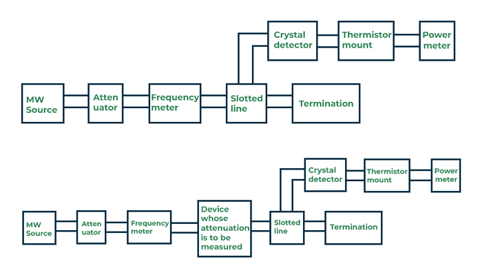
Figure 3. Power Ratio Method
This setup shows how to measure attenuation using the Power Ratio Method. It works by comparing the power before and after a device to see how much signal is lost. The process starts with a microwave (MW) source, followed by an attenuator to adjust signal strength and a frequency meter to monitor the frequency. In the first setup, the signal goes directly to a slotted line, which connects to a crystal detector, thermistor mount, and power meter to measure the output power. A matched termination is used to avoid signal reflections. In the second setup, a device under test is placed between the frequency meter and the slotted line. The same measurements are taken. By comparing the power readings with and without the test device, the attenuation can be calculated. The result is usually given in decibels (dB). This method is simple, reliable, and widely used in RF and microwave testing.
Voltage Ratio Method
When direct power measurement is impractical or introduces complexity, the Voltage Ratio Method provides an effective alternative. Rather than relying on power, which can be challenging to measure accurately particularly in high-frequency systems or compact electronic circuits, this method focuses on voltage, a parameter that is often more accessible and less intrusive to monitor. In many cases, especially where high impedance or delicate components are involved, inserting power meters can disrupt the system’s normal operation. The Voltage Ratio Method circumvents this issue by analyzing voltage levels across known points in the circuit. From these ratios, attenuation can be inferred with a high degree of reliability. This approach is useful in applications such as impedance matching and signal transmission, where maintaining circuit integrity is required.
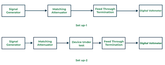
Figure 4. Voltage Ratio Method
The figure shows two setups used in the Voltage Ratio Method, an approach for measuring attenuation when direct power measurement is difficult or disruptive. In both setups, a signal from a generator passes through a matching attenuator to ensure proper impedance. In Setup 1, the signal goes directly to a feed-through termination, and the voltage is measured with a digital voltmeter to establish a reference. In Setup 2, a Device Under Test (DUT) is placed between the attenuator and termination, and the voltage is measured again. By comparing the voltages from both setups, the attenuation or insertion loss caused by the DUT can be calculated using the voltage ratio. This method is useful in sensitive or high-frequency circuits where power meters are impractical.
Audio Frequency (AF) Substitution
Audio Frequency (AF) Substitution is a method used to measure attenuation by evaluating the impact of a specific component on an audio signal's strength. In this technique, an audio signal of known frequency and amplitude is introduced into the system. The output level is first measured without the component under test. Then, the same measurement is repeated with the component inserted into the signal path.The difference between these two output levels indicates the amount of attenuation (or gain) introduced by the component. This approach allows for precise identification of signal loss, aiding in the diagnosis of degraded audio performance, detection of faulty parts, and optimization of system design.

Figure 5. Audio Frequency (AF) Substitution
The figure shows a typical setup for using Audio Frequency (AF) Substitution to measure how much a device, called the Device Under Test (DUT), affects a signal. A 10 MHz signal keeps all parts of the system synchronized. The DUT is connected in line with a precision attenuator to help control the signal strength. The signal then goes through a buffer amplifier and a mixer, where it is converted down to a 10 kHz frequency. This lower frequency makes it easier to work with. After that, the signal is amplified using a very accurate amplifier and compared with a reference signal using an Inductive Voltage Divider (IVD). The difference between the test signal and the reference is measured. A noise generator can be added here to help test how the system responds to interference. A second path in the system helps correct errors. It includes an amplifier, a digital voltmeter, a converter, and a feedback loop that adjusts for any unwanted signal changes. This makes sure the final measurement focuses only on what the DUT is doing to the signal.
Intermediate Frequency (IF) Substitution
The Intermediate Frequency (IF) Substitution Method improves measurement accuracy by converting the original RF signal to a lower, intermediate frequency, where signal analysis is more stable and manageable. This technique uses a standard attenuator in conjunction with high-precision phase detectors to accurately characterize system behavior. Operating at a fixed, lower frequency minimizes the effects of high-frequency noise and instability, enhancing overall measurement reliability. The method is effective in applications that require strict control over both amplitude and phase such as radar system calibration, advanced communication systems, and high-precision testing environments. Its ability to isolate and fine-tune signal parameters makes it a preferred choice for signal fidelity.
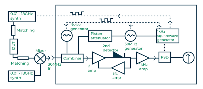
Figure 6. Intermediate Frequency (IF) Substitution
This figure shows how the IF Substitution Method is used to measure signal attenuation with high accuracy. A signal from 0.01 to 18 GHz is sent through the Device Under Test (DUT). The output is converted to a 30 MHz intermediate frequency (IF), which is easier to measure. The 30 MHz IF signal is combined with a reference signal and controlled noise using a piston attenuator. The reference signal is modulated by a 1 kHz square wave to help the system detect changes more clearly. After combining, the signal goes through amplifiers and is picked up by a second detector. A phase-sensitive detector (PSD) then extracts accurate amplitude and phase information. Working at IF helps reduce noise and improve stability, making this method ideal for applications like radar testing, communication systems, and lab measurements where precision is important.
RF Substitution
One effective method for measuring attenuation in radio frequency (RF) systems is the RF substitution technique. In this approach, the component under test (CUT) is temporarily replaced with a calibrated attenuator. This allows for more precise and reliable power measurements by minimizing potential errors caused by inaccuracies or drift in power meters. By substituting the unknown component with a device of known attenuation, testers can accurately determine key performance metrics such as insertion loss or gain. This method enhances measurement consistency and repeatability, making it a trusted approach in RF system evaluation.

Figure 7. RF Substitution
This figure shows the basic setup used in the RF Substitution Method for measuring attenuation in RF systems. A microwave (MW) source generates a signal that passes through an attenuator and a frequency meter before entering the network being tested. The signal then moves through a slotted line, which helps measure signal behavior, and continues to a termination to absorb the signal properly. Two detection paths are used: one to a crystal detector and another to a thermistor mount connected to a power meter. These devices measure the signal’s power. In this method, the unknown network is removed and replaced with a calibrated attenuator. The attenuator is adjusted until the power meter shows the same reading as before. The amount of attenuation added gives the value of the original network’s attenuation. This helps reduce errors and gives more accurate results.
OTDR (Optical Time Domain Reflectometer)
An Optical Time Domain Reflectometer (OTDR) is an instrument used to measure attenuation and assess the overall performance of fiber optic links. It operates by transmitting short pulses of light into the fiber and measuring the light that is scattered or reflected back due to irregularities such as splices, bends, or breaks. By analyzing the time delay and intensity of the returning signal, the OTDR can accurately pinpoint the location and severity of losses along the cable. This method is valuable for both initial installation and long-term maintenance of fiber optic networks. OTDRs help ensure the quality of fiber installations by detecting faults, verifying splicing quality, and identifying problems with connectors. Their high precision and non-intrusive testing capabilities make them an important tool in fiber optic diagnostics.

Figure 8. OTDR (Optical Time Domain Reflectometer)
This figure demonstrates the operational process of an Optical Time Domain Reflectometer (OTDR), a widely used method for measuring attenuation in fiber optic systems. The OTDR laser emits short pulses of light into the fiber, which then transmits the signal through the optical cable. As the light travels, any imperfections such as splices, bends, or breaks, cause a portion of the signal to be reflected back toward the source. The reflected light signal travels back through the fiber and is captured by a photodetector. The photodetector converts this optical signal into electrical data, which is then sent to the display unit for analysis. By evaluating the time delay and intensity of the returned signal, the OTDR identifies the location and magnitude of attenuation or faults within the optical cable. This method provides a non-intrusive, precise way to assess the health and performance of fiber optic links.
Attenuation vs. Amplification
|
Aspect |
Attenuation |
Amplification |
|
Definition |
Reduction in signal strength as it propagates from source
to destination. |
Increase in signal strength to compensate for signal
loss. |
|
Nature of Process |
Passive process occurring naturally due to environmental
and material factors. |
Active process carried out using electronic devices. |
|
Cause |
Interference, scattering, absorption, and bending losses. |
Intentionally done using external devices like amplifiers
and repeaters. |
|
Effect on Signal |
Degrades signal quality, causes data loss, and limits
communication range. |
Enhances signal quality, improves reliability, and
extends communication range. |
|
Purpose |
Unwanted effect that reduces performance. |
Corrective measure to counteract attenuation. |
|
Example |
Weakening of TV signals over long cable distances. |
Boosting volume on a radio or using a repeater to
strengthen TV signals. |
|
Devices Involved |
No device; it's an unwanted by-product of transmission. |
Signal boosters, amplifiers, and repeaters are used. |
Attenuation in Optical Fibers
In optical fibers, attenuation refers to the gradual loss of signal strength as light travels through the fiber. This weakening of the light signal can affect the performance and efficiency of fiber optic communication systems, especially over long distances. The main causes of attenuation in optical fibers are:
1. Absorption: This occurs when the optical signal loses energy as heat due to impurities or the inherent properties of the fiber material itself, typically silica. Common impurities include metal ions and hydroxyl (OH⁻) ions, which absorb specific wavelengths of light.
2. Scattering: Light can scatter in different directions when it encounters microscopic variations or irregularities in the fiber’s core material. The most common type of scattering in optical fibers is Rayleigh scattering, which is caused by random fluctuations in the glass density.
3. Bending Losses: Bending losses occur when light escapes from the fiber core due to excessive or improper bending of the optical fiber. These losses can be categorized into two types: macrobending, which refers to large, visible bends that cause the light to leak out of the core, and microbending, which involves tiny, microscopic distortions in the fiber, often resulting from pressure, physical stress, or manufacturing imperfections, leading to scattering of the light within the fiber.
Measuring Optical Attenuation
To quantify attenuation, we use the following logarithmic formula:
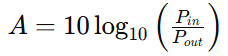
where 𝐴 is the attenuation in decibels (dB), 𝑃𝑖𝑛 is the optical power launched into the fiber, and 𝑃𝑜𝑢𝑡 is the optical power received at the other end. This formula shows how much the signal power has decreased during transmission. A higher attenuation value means more signal loss.
For example, if the input power is 10 mW and the output is 5 mW:

This means the signal has lost half of its power, which corresponds to an attenuation of 3 dB.
Intrinsic vs. Extrinsic Attenuation
Attenuation in optical fibers can be classified into two main categories: intrinsic and extrinsic losses. Intrinsic attenuation refers to losses that are inherent to the fiber’s physical and chemical structure. These include absorption caused by impurities such as hydroxyl ions (OH⁻) and metal particles embedded in the glass during manufacturing, as well as Rayleigh scattering, which results from natural microscopic variations in the fiber's material density. These losses are unavoidable to some extent and are present even in the best-quality fibers. In contrast, extrinsic attenuation arises from external factors that affect the fiber after it has been manufactured. These include poor installation practices such as improper splicing (joining of two fiber ends), sharp bends or kinks in the fiber that exceed its bend radius, and physical stresses from crushing, twisting, or environmental influences. Unlike intrinsic losses, extrinsic losses can often be minimized or prevented through proper handling, installation, and maintenance practices.
Attenuation in Networking
In computer networks, attenuation means the weakening of a signal as it travels. This happens in both wired and wireless connections. When a signal gets too weak, it can cause slow internet speeds, lost data, or dropped connections. The main causes of attenuation in networking are:
1. Distance: The most cause of attenuation is distance. The longer a signal has to travel through a cable or across open space, the more it degrades. In wired networks, especially those using copper-based cables, electrical resistance increases with length, leading to a greater loss of signal strength. This is why cable length limitations exist in networking standards.
2. Frequency: Higher frequency signals are more susceptible to attenuation than lower frequency ones. This is important in wireless communications, where higher frequencies (like those used in Wi-Fi 5 GHz bands) can carry more data but degrade faster and have shorter range than lower frequency signals (like 2.4 GHz). Similarly, in wired systems, high-frequency data transmission can suffer more from signal degradation over the same distance.
3. Noise and Interference: Electromagnetic interference (EMI) from external sources such as fluorescent lights, electrical motors, microwaves, or even other electronic devices can disrupt and weaken signals. Physical obstacles like walls, especially those made of dense materials like concrete or metal, can also absorb or reflect wireless signals, increasing attenuation and reducing overall network performance.
4. Cable Type and Quality: The material and construction of transmission cables impact how much signal is lost over a given distance. Copper cables (such as Cat5e or Cat6) are commonly used for shorter distances but can experience more attenuation than fiber optic cables. Fiber optic cables, which transmit data using light rather than electrical signals, are far less prone to signal loss and interference, making them ideal for high-speed and long-distance connections.
Measurement of Attenuation in Networking
In networking, attenuation refers to the gradual loss of signal strength as it travels through a medium such as copper wire, fiber optic cable, or air. It is measured in decibels (dB) and can be calculated using either power-based or voltage-based formulas, depending on the context. When measuring signal power, the attenuation is calculated using the formula:
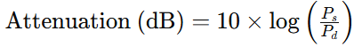
where Ps is the signal power at the source and Pd is the signal power at the destination. This formula reveals how much the signal has weakened between transmission and reception. For example, if a signal starts at 100 mW and is received at 10 mW, the attenuation is:

On the other hand, when dealing with voltage in systems where impedance remains constant, attenuation is calculated differently. The appropriate formula in this case is:
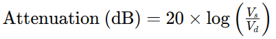
where Vs is the voltage at the source and Vd is the voltage at the destination. This accounts for the fact that power in resistive systems is proportional to the square of voltage. For instance, if a signal drops from 2 V to 1 V, the attenuation would be:

Attenuation in Signal Transmission
Attenuation means a signal gets weaker as it travels from one place to another. This happens in both wired (like copper cables) and wireless (like Wi-Fi) systems, and the longer the signal has to travel, the more it fades.
Wired Systems
In wired communication, especially in copper cables and coaxial lines, attenuation occurs primarily due to the physical properties of the transmission medium. Several factors contribute to this signal degradation:
• Electrical Resistance: All conductors have some inherent resistance. As the electrical signal travels through the wire, some of its energy is converted into heat, causing a gradual loss in strength. Thinner wires have higher resistance, which leads to more severe attenuation compared to thicker cables.
• Skin Effect: At higher frequencies, the electrical signal tends to travel along the surface of the conductor. This reduces the effective area for current flow and increases resistance, worsening attenuation.
• Capacitive and Inductive Effects: Long cables can act like capacitors or inductors, especially when multiple wires are bundled together. These properties can cause distortion and loss of signal over time.
• Impedance Mismatch: If the transmission line isn’t properly matched to the load or source impedance, part of the signal can be reflected back, further weakening the original signal.
• External Electromagnetic Interference (EMI): Nearby electrical equipment, power lines, or radio signals can introduce noise into the system, effectively masking or degrading the intended signal.
• Poor Installation or Degraded Materials: Improper connections, corrosion in the wires, or wear and tear over time can cause increased resistance and greater signal loss.
• Environmental Factors: High temperatures, moisture, or physical stress on the cables can alter their electrical characteristics, resulting in higher attenuation.
Wireless Systems
In wireless communication, signals travel through the air and are susceptible to a different set of challenges. Attenuation in these systems is influenced by both the medium (air) and the environment in which the signal propagates.
• Free-Space Path Loss (FSPL): As a radio signal radiates out from a transmitter, it spreads over an increasingly larger area. This natural spreading results in signal strength diminishing with distance, even in a vacuum.
• Obstructions: Solid objects like walls, buildings, trees, and even human bodies can block or absorb radio signals, reducing the strength of the signal that reaches the receiver.
• Reflection, Refraction, and Diffraction: Signals can bounce off surfaces (reflection), bend when passing through different materials (refraction), or curve around edges (diffraction). These effects can cause parts of the signal to arrive out of sync, leading to multi-path interference and loss of clarity.
• Atmospheric Conditions: Rain, fog, and humidity can absorb or scatter radio waves, particularly at higher frequencies (e.g., in the GHz range), causing signal weakening.
• Interference from Other Devices: Wi-Fi, Bluetooth, microwave ovens, and other wireless systems often operate in overlapping frequency bands. This overlap can cause interference, making it harder for a receiver to distinguish the intended signal.
• Antenna Quality and Alignment: Poorly designed or misaligned antennas can result in weak transmission or reception, increasing effective attenuation.
Measurement of Attenuation in Signal Transmission
Attenuation is quantified in decibels (dB), a logarithmic unit that compares the strength of the signal at its source to its strength after transmission. The standard formula used for calculating attenuation based on power levels is:

where Pin is the input signal power, Pout is the output signal power. If signal strength is measured by voltage, common in low-power or audio scenarios, the formula becomes:

where Vin is the input voltage, Vout is the output voltage. These calculations provide a standardized method to quantify signal loss. A higher dB value indicates greater attenuation. In applications such as fiber optics, Ethernet, or radio frequency systems, attenuation is often expressed per unit length (e.g., dB/km or dB/m). Many use tools like optical power meters, network analyzers, or OTDRs (Optical Time-Domain Reflectometers) to perform these measurements, depending on the transmission medium. Precise attenuation measurement is require for system design and upkeep, ensuring signal quality, minimizing errors, and maintaining dependable communication across networks.
Advantages and Disadvantages of Attenuation
Advantages of Attenuation
Signal Strength Control: Attenuation allows for the precise management of signal strength within a system. In many electronic and communication applications, especially in sensitive circuits, excessively strong signals can cause distortion or even permanent damage to delicate components. Attenuators help regulate these signal levels to ensure they stay within optimal operating parameters, preserving signal integrity and protecting equipment.
Prevents Overloading: When signals are too strong, they can exceed the voltage or power ratings of downstream components, leading to overloading. This not only introduces distortion but can also compromise the safety and functionality of devices. Attenuation ensures that all parts of the system receive signals within safe and manageable levels, extending component lifespan and improving reliability.
Noise Reduction: In certain scenarios, strong signals can pick up or amplify unwanted noise or interference from the environment. By reducing the amplitude of the signal to a more manageable level, attenuation can help mitigate the effects of such interference. This leads to cleaner, higher-quality signals, important in audio, video, and radio frequency (RF) systems.
Testing and Calibration: Attenuators are commonly used in laboratory and field environments to simulate conditions and to test the performance of devices under various signal strengths. By adjusting signal levels precisely, you can calibrate instruments, verify tolerances, and validate system behavior without risking equipment damage.
Improves System Stability: In complex systems such as those involving audio mixing, RF transmission, or telecommunications, attenuation contributes to overall stability by smoothing out signal fluctuations. Stable signals reduce the chance of oscillations, feedback, or unexpected behavior, particularly in systems with multiple amplifiers or feedback loops.
Disadvantages of Attenuation
Signal Loss: The primary downside of attenuation is that it inherently reduces the amplitude or power of a signal. While this is sometimes necessary, it can also lead to a loss of information, particularly if the signal is already weak. In digital communications, this loss can degrade signal clarity and make it more difficult to extract useful data at the receiving end.
Limited Transmission Range: As signal strength diminishes due to attenuation, the effective range of transmission is reduced. This is problematic in wireless communication or long-distance wired systems, where signals must travel considerable distances. Without compensation, attenuation can prevent the signal from reaching its destination with sufficient strength.
Increased Cost: To counteract the effects of signal loss, systems often require additional components such as amplifiers, repeaters, or signal boosters. These extra devices increase the overall cost of the system, not just in terms of hardware but also in installation, power consumption, and maintenance.
System Complexity: Incorporating attenuation into a system design adds a layer of complexity. You must carefully calculate the appropriate attenuation levels and determine where compensating amplification is needed. This increases the design burden and can make troubleshooting and maintenance more challenging, especially in large or distributed systems.
Higher Error Rates: In digital communication systems, reduced signal strength due to attenuation can lead to a higher probability of bit errors. As signals weaken, they become more susceptible to noise and interference, making it harder for receivers to correctly interpret the data. This can result in communication failures or the need for more robust error correction mechanisms, which may introduce latency or further complexity.
Applications of Attenuation
Attenuation, the intentional weakening of a signal is an important idea in many electronic, communication, and measurement systems. It helps make sure signals are handled safely, efficiently, and accurately in different settings. Here are some areas where attenuation is important:
Volume Control in Electronic Audio Equipment
In electronics such as radios, televisions, amplifiers, and personal audio devices, attenuation is commonly employed to manage sound levels. By varying the degree of signal attenuation before it reaches the amplification stage, you can smoothly adjust audio output without affecting the integrity of the signal path. This approach provides precise, distortion-free volume control, for maintaining audio clarity and comfort.
Power Level Regulation in Optical Fiber Communication Systems
In fiber-optic networks, attenuation is used to regulate the intensity of transmitted optical signals. Optical attenuators are placed to reduce signal power, ensuring it remains within the optimal dynamic range of the photodetector at the receiving end. Without attenuation, high-power signals especially over short links or following amplification, could saturate or damage sensitive receivers. Proper attenuation ensures consistent signal quality, minimizes bit error rates, and contributes to the overall reliability of data transmission across the network.
Instrument Protection in RF Signal Measurement
In radio frequency (RF) testing and diagnostic environments, attenuators are important for protecting delicate instruments such as spectrum analyzers, network analyzers, and power meters. During signal analysis, especially at high power levels, direct input without attenuation could overwhelm or damage these tools. Attenuators help scale down the signal to a safe and measurable level, allowing for accurate readings and preventing costly equipment failures. They also contribute to maintaining the linearity and calibration accuracy of the measuring devices.
Safe Voltage Scaling in Laboratory Experiments
Educational and research laboratories often utilize attenuators as a means to reduce voltage levels during experimental work. This is important when analyzing the response of circuits or components under low-voltage conditions. Attenuation ensures the safety of both the user and the equipment, without risking component burnout or inaccurate results due to excessive input levels.
Circuit Protection in Analog and Digital Electronics
Integrated circuits (ICs) and other electronic components are highly sensitive to voltage levels that exceed their rated specifications. Attenuators serve as a first line of defense in many analog and digital systems by limiting incoming signal amplitudes. This is useful in signal conditioning, where raw inputs must be scaled down before processing by analog-to-digital converters (ADCs) or microcontrollers. By reducing high signal levels to manageable values, attenuation safeguards circuitry from voltage spikes and ensures long-term system reliability.
Impedance Matching and Signal Integrity with Fixed Attenuators
In high-frequency applications such as RF, microwave, and antenna systems, fixed attenuators play a role in impedance matching. Impedance mismatches can lead to signal reflections, power loss, and interference, all of which degrade system performance. By introducing a known amount of attenuation while preserving consistent impedance (typically 50 or 75 ohms), fixed attenuators help minimize signal reflections and maximize power transfer. This contributes to maintaining signal integrity in complex transmission line environments.
Conclusion
Attenuation is a normal part of how signals travel, but if it’s not managed, it can cause problems like poor sound, slow internet, or lost data. This guide showed how signals get weaker, how we measure that loss, and how to fix or control it using tools and techniques. Understanding attenuation helps make sure systems work better, stay safe, and last longer, whether you're working with cables, wireless networks, or audio equipment.
About us
ALLELCO LIMITED
Read more
Quick inquiry
Please send an inquiry, we will respond immediately.
Frequently Asked Questions [FAQ]
1. What is attenuation in transmission impairments?
Attenuation in transmission impairments refers to the gradual loss of signal strength as it travels through a medium like a cable, fiber optic line, or air. This weakening happens because of resistance, interference, or material imperfections that absorb or scatter the signal. As the signal moves farther from its source, it becomes weaker and may degrade to the point where the receiver can no longer interpret it clearly. Attenuation is a common issue in both wired and wireless systems and needs to be managed to maintain communication quality.
2. What is the relationship between frequency and attenuation?
The relationship between frequency and attenuation is that higher-frequency signals usually experience more attenuation than lower-frequency ones. This is because high-frequency signals are more easily absorbed by the transmission medium and more affected by factors like skin effect in cables, dielectric losses, or scattering in optical fibers. As frequency increases, the signal tends to lose strength faster, especially over long distances. That’s why high-frequency systems often need better shielding, higher-quality materials, or more signal boosting compared to low-frequency ones.
3. What is the purpose of attenuation?
The purpose of attenuation is to control the signal level to prevent distortion, damage, or overload of sensitive equipment. In many systems, especially in testing, audio, or communication devices, a signal might be too strong and needs to be reduced to a manageable level. Attenuation ensures that the signal matches the input range of a receiver or measuring device, keeps the system stable, and avoids interference or noise problems. It also plays a role in balancing signal strength in networks and helps in impedance matching.
4. What does 10db attenuation mean signal strength?
A 10 dB attenuation means the signal has lost 90% of its original power. In other words, only 10% of the original power reaches the output. Since decibels use a logarithmic scale, a 10 dB reduction corresponds to the output power being one-tenth of the input power. If you had 100 mW at the start, a 10 dB attenuated signal would have 10 mW at the end. This level of loss is significant and usually needs to be compensated for using amplifiers if the signal needs to travel further or remain usable.
5. What is the best SNR and line attenuation?
The best Signal-to-Noise Ratio (SNR) is a high value usually above 30 dB which means the signal is much stronger than the background noise, resulting in clearer and more stable communication. Lower SNR values (below 20 dB) can cause slow speeds or data loss. For line attenuation, lower is better because it means the signal is not losing much strength during transmission. A line attenuation below 20 dB is ideal for most high-speed internet or data lines. High attenuation (above 40 dB) may lead to errors and slower performance unless corrected with repeaters or amplifiers.
A Quick Guide to the XC2V250-5FG456I FPGA
on April 15th
What Makes XCS30XL-4VQG100C a Smart FPGA Choice
on April 11th
Popular Posts
-

Complex Instruction Set Computers: How They Changed Computing?
on April 18th 147753
-

USB-C Pinout and Features
on April 18th 111925
-

Using Xilinx Unified Simulation Primitives: A Comprehensive Guide to FPGA Design and Simulation
on April 18th 111349
-

Power Supply Voltages in Electronics: Meaning of VCC, VDD, VEE, VSS, and GND
on April 18th 83714
-

RJ45 Connector Guide: Pinout, Wiring, Cable Types, and Uses
on January 1th 79502
-

The Ultimate Guide to Wire Color Codes in Modern Electrical Systems
The way our electrical systems use colors isn’t just for looks. Each wire color now indicates a specific function, making it easier to identify and handle electrical components correctly during ins...on January 1th 66872
-

Quality (Q) Factor: Equations and Applications
The quality factor, or 'Q', is important when checking how well inductors and resonators work in electronic systems that use radio frequencies (RF). 'Q' measures how well a circuit minimizes energy...on January 1th 63005
-

Purge Valve Guide: Function, Symptoms, Testing, and Replacement for Optimal Engine Performance
The purge valve is a key part of a car’s system that helps keep the air clean by managing fuel vapors before they can escape into the atmosphere. This not only helps the environment by reducing pol...on January 1th 62956
-

Achieving Peak Performance with the Maximum Power Transfer Theorem
The Maximum Power Transfer Theorem explains how energy from a source, such as a battery or generator, flows to a connected load. It shows the exact condition where the load receives the most power....on January 1th 54078
-

A23 Battery Specifications and Compatibility
The A23 battery is a small, cylinder-shaped battery with high voltage. Also called 23A, 23AE, or MN21, it runs at 12 volts and much higher than AA or AAA batteries. Its special design make...on January 1th 52092
HOT Part Number
-

RMPA0959
onsemi
IC RF AMP CELL 824-849MHZ 11LCC
RCLAMP0554S.TCT
Semtech Corporation
TVS DIODE 5VWM 15VC SOT23-6
CM453232-R47KL
Bourns Inc.
FIXED IND 470NH 545MA 320MOHM SM
744028002
Würth Elektronik
FIXED IND 2.2UH 1.3A 155MOHM SMD
MIC3809YMM
Microchip Technology
IC REG CTRLR MULT TOPOLOGY 8MSOP
AONS36302
Alpha & Omega Semiconductor Inc.
MOSFET N-CH 30V 146A 8DFN
SP3238EEA-L/TR
MaxLinear, Inc.
IC TRANSCEIVER FULL 5/3 28SSOP
BF5020WH6327
Infineon Technologies
N-CHANNEL POWER MOSFET
C1608X8R1H102M080AE
TDK Corporation
CAP CER 1000PF 50V X8R 0603
TPS71525QDCKRQ1
Texas Instruments
IC REG LINEAR 2.5V 50MA SC70-5
170M5444
Eaton - Bussmann Electrical Division
FUSE SQUARE 500A 1.3KVAC RECT
IHLP4040DZER220M1A
Vishay Dale
IHLP-4040DZ-1A 22 20% ER E3
C0603X181J1HACAUTO
KEMET
CAP CER 0603 180PF 100V ULTRA ST
PIC16F1575-E/JQ
Microchip Technology
IC MCU 8BIT 14KB FLASH 16UQFN
OPA4354AIPWR
Texas Instruments
IC CMOS 4 CIRCUIT 14TSSOP
P6SMB33A
Bourns Inc.
TVS DIODE 28.2VWM 45.7VC DO214AA
GCM1885C1H4R4CA16D
Murata Electronics
CAP CER 4.4PF 50V C0G/NP0 0603
R5F100LGAFB#10
Renesas Electronics America Inc
IC MCU 16BIT 128KB FLASH 64LFQFP -
TC621CCOA
Microchip Technology
THERMOSTAT PROG ACTIVE LOW 8SOIC
IRG4BC20UDPBF
International Rectifier
IGBT, 13A I(C), 600V V(BR)CES, N
MICROSMD175F-2
Littelfuse Inc.
PTC RESET FUSE 6V 1.75A 1210
AC0603KRX7R8BB222
YAGEO
CAP CER 2200PF 25V X7R 0603
1812AA150JAT1A\SB
KYOCERA AVX
CAP CER 15PF 1KV NP0 1812
SY10ELT22ZC
Microchip Technology
IC TRANSLTR UNIDIRECTIONAL 8SOIC
SCW03B-12
MEAN WELL USA Inc.
DC DC CONVERTER 12V 3W
A4840
Sensata-Crydom
SSR RELAY SPST-NO 40A 80-530V
TC4426AEOA
Microchip Technology
IC GATE DRVR LOW-SIDE 8SOIC
C1608NP01H470J080AA
TDK Corporation
CAP CER 47PF 50V NP0 0603
GRM1555C2A8R1DA01J
Murata Electronics
CAP CER 8.1PF 100V C0G/NP0 0402
INA330AIDGST
Texas Instruments
IC OPAMP GP 1 CIRCUIT 10VSSOP
12061C273KAT2A
KYOCERA AVX
CAP CER 0.027UF 100V X7R 1206
74LX1G70CTR
STMicroelectronics
IC BUF NON-INVERT 5.5V SOT323-5
CSNE151-204
Honeywell Sensing and Productivity Solutions
SENSOR CURRENT HALL 90A AC/DC
LF353DT
STMicroelectronics
IC OPAMP JFET 2 CIRCUIT 8SOIC
SMK316B7223KLHT
Taiyo Yuden
CAP CER 0.022UF 630V X7R 1206
R9G01612XX
Powerex Inc.
DIODE GP 1.6KV 1200A DO200AB -
FPF2300MPX
Fairchild Semiconductor
DUAL OUTPUT CURRENT LIMIT SWITCH
HZB6.8MWATL-E
Renesas Electronics America Inc
TVS DIODE 3.5VWM 3CMPAK
P0111MA 1AA3
STMicroelectronics
SCR 600V 800MA TO92-3
88E1545-A1-LKJ2C000
Marvell Semiconductor, Inc.
IC TXRX FULL/HALF 4/4 128LQFP
MAX809SN293D1T1G
onsemi
IC SUPERVISOR 1 CHANNEL SOT23-3
ICL3232IBZ-T
Renesas Electronics America Inc
IC TRANSCEIVER FULL 2/2 16SOIC
EP1K50FI484-2
Altera
LOADABLE PLD, 0.4NS PBGA484
FDMF6824C
onsemi
IC HALF BRIDGE DRIVER 50A 40PQFN
HVD144AKRF-E
Renesas Electronics America Inc
PLANAR PIN DIODE
MCD56-12IO1B
IXYS
MOD THYRISTOR/DIO 1200V TO-240AA
CD3275A0DRCR
Texas Instruments
PROTOTYPE
SN74ALS240ANSR
Texas Instruments
IC BUFFER INVERT 5.5V 20SO
9FG104EGLF
Renesas Electronics America Inc
IC FREQ TIMING GENERATOR 28TSSOP
MPC8548EVTAUJB
Freescale Semiconductor
MPU, 32-BIT, 1333MHZ, PBGA783
NCP1070STCT3G
onsemi
IC OFFLINE SWITCH FLYBACK SOT223
MIC4422YM
Microchip Technology
IC GATE DRVR LOW-SIDE 8SOIC
BU2510-E3/51
Vishay General Semiconductor - Diodes Division
BRIDGE RECT 1P 1KV 3.5A BU
GS8642Z36GB-167IV
GSI Technology Inc.
IC SRAM 72MBIT PARALLEL 119FPBGA