
Understanding T Flip-Flops: Working, Construction, and Applications in Digital Circuits
This guide explains what a T flip-flop is and how it works in digital circuits. The guide shows how this flip-flop holds memory of its past state, and how to build a T flip-flop using other types of flip-flops like SR, D, or JK. You’ll learn how it can be used to divide frequencies, how it works in a simple 2-bit memory setup, and where it is used in digital systems.Catalog

What is a T Flip-Flop?
A T flip-flop, or toggle flip-flop, is a type of sequential logic circuit that stores one bit of data and changes its output state only when the toggle (T) input is high during a triggering clock edge. Unlike combinational circuits, which respond only to current inputs, T flip-flops retain a memory of past states, making their behavior dependent on both the present input and the previous output. The outputs, labeled Q and Q’ (the inverse of Q), are always complementary. This means when Q is 1, Q’ is 0, and vice versa. Internally, logic gates and feedback mechanisms are used to create this toggling action.
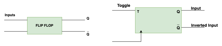
Figure 2. Block Diagram of T Flip Flop
As illustrated in the left diagram, a generic flip-flop has input signals and two outputs Q and Q’ which represent the current state and its inverse. The right diagram focuses specifically on the T flip-flop, where the T input determines whether the state should toggle on a clock edge. If T is 0, the output remains the same. If T is 1, the output Q switches from 0 to 1 or 1 to 0, depending on its current state. This toggle behavior, combined with its memory function, allows the T flip-flop to support sequential state transitions in digital systems.
How a T Flip-Flop Works?

Figure 3. T Flip-Flop Logic Circuit
The T flip-flop responds to two conditions: the clock (CLK) signal and the value of the T input. In the circuit diagram above, the T flip-flop is implemented using logic gates. Here's how it functions:
• When T = 0
The upper AND gate (labeled 1) and the lower AND gate (labeled 2) both output 0 regardless of the clock signal, because one of their inputs is 0. This prevents any change in the outputs of the NOR gates (labeled 3 and 4), which means the flip-flop holds its state. The outputs Q and Q̅ remain as they were before the clock pulse.
• When T = 1
Now both AND gates are activated by the clock signal (CLK). Depending on the current state of Q and Q̅, one of the AND gates will allow a signal through, triggering the corresponding NOR gate and toggling the state of the flip-flop. That is:
If Q = 0, it switches to Q = 1
If Q = 1, it switches to Q = 0
The toggling action is synchronized with the clock, ensuring changes only occur on specific clock transitions (usually rising or falling edges, depending on the final implementation). This characteristic (holding when T = 0, and toggling when T = 1 on a clock edge) makes the T flip-flop a useful building block in digital systems such as counters, frequency dividers, and synchronized control circuits.
Truth Table for T Flip-Flop
The truth table helps visualize how the T flip-flop responds:
|
T |
Q (Current) |
Q_next |
|
0 |
0 |
0 |
|
0 |
1 |
1 |
|
1 |
0 |
1 |
|
1 |
1 |
0 |
When T is 0, the next state matches the current state.
When T is 1, the output flips.
This predictable behavior allows to easily simulate and test T flip-flops in broader digital systems.
How to Build a T Flip-Flop?
T flip-flops can be created using other types of flip-flops: SR, D, or JK. Each method changes the inputs of the base flip-flop to mimic toggle behavior.

Figure 4. T Flip-Flop Methods
Using an SR Flip-Flop
The figure below illustrates how a T flip-flop can be constructed using an SR flip-flop with the help of two AND gates. In this configuration, the T input is connected to both AND gates along with either the Q or Q’ output. One AND gate takes the T input and the Q’ output to generate the Set (S) signal, while the other AND gate takes T and Q to produce the Reset (R) signal. These signals then feed into the SR flip-flop, which is made up of cross-coupled NOR gates responsible for maintaining or changing the state of outputs Q and Q’.
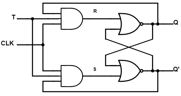
Figure 5. T Flip Flop Using SR Flip Flop
When the T input is 0, both AND gates are disabled, meaning S and R remain low, and the flip-flop retains its current state. However, when T is 1, the output state toggles depending on the current state: if Q is 0, Q’ is 1, triggering the S input and setting Q to 1; if Q is 1, Q’ is 0, activating the R input and resetting Q to 0. This ensures toggling behavior. Care must be taken to prevent both S and R from being high at the same time, as this would lead to an invalid or unpredictable output from the SR flip-flop.
Using a D Flip-Flop
The figure below demonstrates how a T flip-flop can be implemented using a D flip-flop and an XOR gate. In this configuration, the XOR gate takes the T input and the current Q output of the D flip-flop. The output of the XOR gate is then connected to the D input. This setup ensures that the input to the D flip-flop is determined by the XOR of T and Q, effectively controlling whether the state should be held or toggled on each clock pulse.

Figure 6. T Flip Flop Using D Flip Flop
When T is 0, the XOR gate outputs the current value of Q, so the D flip-flop maintains its state. When T is 1, the XOR gate outputs the inverse of Q, which is then latched on the next clock edge, causing the output to toggle. This method is efficient and avoids the pitfalls of undefined states that may arise in other flip-flop types. It uses minimal hardware (just one XOR gate in addition to the D flip-flop) making it a compact and reliable design for T flip-flop functionality.
Using a JK Flip-Flop
The figure below shows how a T flip-flop can be easily built using a JK flip-flop by directly connecting the T input to both the J and K inputs. The circuit leverages the natural toggling behavior of the JK flip-flop when both inputs are high. The T signal is routed to both AND gates that serve as the J and K logic, along with the clock signal, to control the timing of the toggling action.
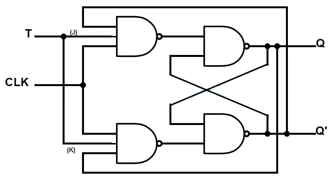
Figure 7. T Flip Flop Using JK Flip Flop
When T is 0, both J and K are 0, so the JK flip-flop maintains its current state. When T is 1, both J and K are high, and the JK flip-flop toggles its output Q on each rising edge of the clock. This design requires no additional gates beyond what's already in the JK flip-flop, making it one of the most efficient and high-speed methods for implementing a T flip-flop. It is reliable, compact, and ideal for applications where simplicity and performance are needed.
Frequency Division with T Flip-Flops
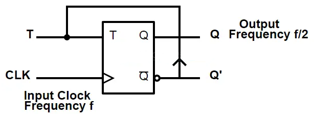
Figure 8. Frequency Division with T Flip-Flops
T flip-flops are very useful in digital electronics for dividing frequencies. They are simple devices that change their output state (toggle) every time they receive a clock pulse, but only if the T input is set to 1 (or HIGH). In the figure above, you can see a T flip-flop where the Q’ (inverted) output is connected back to the T input. This setup ensures that the flip-flop will toggle its state every time a clock signal (CLK) is received.
When this happens, the output at Q changes from 0 to 1 or 1 to 0 with each clock pulse. This means the flip-flop only completes a full cycle every two clock pulses. As a result, the frequency of the Q output becomes half of the input clock frequency. For example, if the input clock has a frequency of 10 Hz (10 pulses per second), the output Q will toggle at 5 Hz, effectively dividing the frequency by 2.
This frequency division capability becomes even more powerful when you connect multiple T flip-flops in a series, also known as cascading. When the Q output of one flip-flop feeds into the clock input of the next flip-flop, each stage continues to divide the frequency by 2. The first flip-flop gives an output of f/2, the second gives f/4, the third f/8, and so on. This creates a chain of flip-flops that divide the original frequency by powers of two.
2-Bit Parallel Load Register Using T Flip-Flops

Figure 9. 2-Bit Parallel Load Register Using T Flip-Flops
A 2-bit parallel load register is a digital circuit that can store two bits of data at once. The figure above shows how we can build this using T flip-flops, XOR gates, and 2-to-1 multiplexers (MUXes). Each bit in the register has its own set of components: one T flip-flop, one XOR gate, and one multiplexer.
Here's how it works step by step. First, the XOR gate compares the current input bit (X0 or X1) with the current output of the flip-flop (Q0 or Q1). If the input is different from the output, the XOR gate sends a 1 to the multiplexer. This means the T flip-flop needs to toggle to match the new data. If the input and output are the same, the XOR sends 0, meaning no toggle is needed because the output is already correct.
Next, the 2-to-1 multiplexer decides whether to load new data or keep the current state. It does this based on the control signal (C). If the control signal is 0, the MUX sends 0 to the T input, which tells the flip-flop to hold its current value (no toggle). But if the control signal is 1, the MUX passes the result from the XOR gate to the T input, allowing the flip-flop to toggle only if needed. This way, when loading is enabled, both flip-flops update their outputs at the same time during the next clock edge.
This setup allows the register to load two bits of data in parallel, meaning both bits are updated at the same time using a single clock pulse. It’s efficient and useful in systems that need to transfer or store small chunks of data quickly. The design is also scalable, which means more bits can be added by copying the same pattern with more T flip-flops, XOR gates, and multiplexers. This makes it a good choice for building simple memory circuits or temporary data storage in digital systems.
Advantages of T Flip-Flops
• Simple Design: T flip-flops are constructed with only a single input, which simplifies both their internal circuitry and external wiring requirements. This streamlined configuration reduces the number of logic gates and interconnections needed, making them easier to design, analyze, and implement. As a result, T flip-flops are advantageous in systems where space, cost, or complexity must be minimized.
• Predictable Behavior: Unlike SR (Set-Reset) flip-flops, which can enter an undefined or unstable state when both inputs are active simultaneously, T flip-flops offer consistent and reliable behavior. Their toggling nature ensures a clear, deterministic output based solely on the clock signal and the T input. This predictability makes them well-suited for use in digital systems that require stability and dependability.
• Efficient for Counting: T flip-flops naturally toggle their output on each active clock pulse when the T input is high, making them ideal building blocks for binary counters and frequency dividers. Each T flip-flop in a counter chain divides the clock frequency by two, allowing easy construction of multi-bit counters. Their ability to switch states predictably with each pulse simplifies the logic needed for accurate and synchronized counting operations.
• Low Power Consumption: When the T input is low, the flip-flop maintains its current state and does not change on the clock pulse. This behavior reduces unnecessary switching activity within the circuit, thereby conserving power. In low-power applications or battery-operated devices, this can enhance energy efficiency and extend operational life.
• Reliable Memory Storage: T flip-flops act as stable memory elements that retain their state until a clock signal and an active T input prompt a toggle. This inherent stability ensures data integrity over time, especially in timing-sensitive digital applications. Their dependable performance in holding and updating binary information makes them an important component in memory circuits and state machines.
Disadvantages of T Flip-Flops
• Limited Functionality: T flip-flops are designed to perform only one specific operation, toggling the output state on each triggering clock pulse when the T input is high. Unlike other types of flip-flops (such as JK or D flip-flops), they lack the flexibility to perform set, reset, or data latch functions without additional external logic. This restricts their direct application in systems requiring more complex or conditional logic behavior, necessitating extra circuitry to extend their capabilities.
• Sensitive to Glitches: T flip-flops can be vulnerable to glitches or brief voltage spikes on either the T input or the clock signal. Because they toggle their state based on signal transitions, even a short-lived pulse caused by noise or interference may inadvertently trigger a state change. In high-speed or electrically noisy environments, this sensitivity can lead to erratic behavior, requiring careful signal conditioning or debouncing mechanisms to maintain reliability.
• Timing Complexity: In digital systems that use many T flip-flops especially in cascaded counter arrangements, timing coordination becomes increasingly challenging. Each flip-flop introduces a delay, and without precise synchronization, this can result in skewed outputs or timing mismatches. You must pay close attention to clock distribution, setup times, and hold times to ensure correct operation, which adds complexity to system timing analysis and layout.
• Single-Bit Only: Each T flip-flop is capable of storing and processing only a single bit of information. For operations that involve multi-bit data, such as counting beyond one bit or storing larger binary values, multiple T flip-flops must be combined in more complex arrangements. This increases the number of components, the amount of wiring, and the overall system complexity, which can be a disadvantage in space- or cost-sensitive designs.
• Propagation Delay: When T flip-flops are connected in sequence (as is common in counters) the output of one flip-flop becomes the input to the next. This chain introduces cumulative propagation delays, where each stage must wait for the previous one to settle before responding. In high-speed circuits, these delays can degrade overall performance, reduce maximum operating frequency, and create synchronization issues, especially in longer chains or deeper circuits.
Applications
T flip-flops are used in a wide range of digital systems:
Frequency Dividers
T flip-flops are commonly used in frequency divider circuits, where the output toggles on each incoming clock pulse. This effectively divides the input clock frequency by two. By cascading multiple T flip-flops, it's possible to divide the frequency further (by 4, 8, 16, etc.). These frequency-divided signals are use in applications such as digital watches, communication systems, and microcontroller timing where slower, synchronized clock signals are required for different components.
Counters
Because T flip-flops toggle their state with each clock pulse, they serve as the elements in binary counters. These counters are used in a wide range of digital devices such as digital clocks, event counters, odometers, and timers. Each flip-flop in the counter represents one bit, and their sequential toggling allows for counting in binary, enabling accurate time or event tracking in digital systems.
Shift Registers
While T flip-flops themselves are not typically used as the main elements in shift registers (D flip-flops are more common), they can assist in timing and control logic for such registers. In the broader context of serial-to-parallel or parallel-to-serial data conversion, T flip-flops may be used to generate synchronized control pulses that dictate when data is shifted, making them useful in communication systems, data storage, and digital signal processing.
Control Logic
In state machines and control systems, T flip-flops can be used to manage state transitions in a predictable and toggled fashion. They help implement control sequences where the output needs to alternate between states on specific conditions. This is valuable in traffic light controllers, vending machines, and robotic systems, where the control flow must respond to clocked input events in a reliable sequence.
Memory Circuits
T flip-flops can function as simple one-bit memory elements by holding a binary state until the next toggling event. In registers and storage arrays, they can be used to store flags, enable bits, or binary data temporarily. Though more commonly replaced by D flip-flops in complex memory architectures, T flip-flops still find use in smaller, specialized registers where toggling behavior aligns with the logic design requirements.
Conclusion
The T flip-flop is a simple and useful part for digital electronics. It stores one bit and changes (toggles) its output only when told to, making it great for counting and dividing signals. You can build it in different ways using other flip-flops, and it works well in systems that need a signal to flip on and off at the right time. T flip-flops are easy to use, save power, and are good for building counters, timers, and small memory parts. But they also have limits, they only handle one bit, are sensitive to signal noise, and can cause delays when used in long chains. Even with these downsides, T flip-flops are still widely used because of their simple and reliable behavior.
About us
ALLELCO LIMITED
Read more
Quick inquiry
Please send an inquiry, we will respond immediately.
Frequently Asked Questions [FAQ]
1. What is the basic principle of T flip-flop?
The basic idea behind a T flip-flop is that it changes its output value every time it receives a clock signal, but only if the T input is set to 1. If T is 0, the output stays the same. If T is 1, the output flips from 0 to 1 or 1 to 0 with each clock pulse. This behavior makes it act like a switch that turns on and off in a regular pattern. It also stores the current output until the next clock signal comes, giving it memory-like behavior.
2. How do you tell if a flip-flop is positive or negative?
To find out if a flip-flop is positive or negative edge-triggered, you need to look at how it reacts to the clock signal. If it responds when the clock signal goes from 0 to 1 (rising edge), it is a positive-edge flip-flop. If it reacts when the clock goes from 1 to 0 (falling edge), it is a negative-edge flip-flop. This is often shown in diagrams: a triangle at the clock input means positive edge, and a triangle with a small circle means negative edge.
3. What is the characteristic equation of the T flip-flop?
The characteristic equation of a T flip-flop is Q(next) = T XOR Q(current). This means the next output depends on the current output and the value of T. If T is 0, the output stays the same. If T is 1, the output changes to the opposite value. This equation shows exactly how the flip-flop decides what the next state should be based on the T input and its current state.
4. What is the difference between flip-flop and T flip-flop?
A flip-flop is a general name for a circuit that stores one bit of data. There are different types of flip-flops, like SR, D, JK, and T. Each type has a different way of working. The T flip-flop is a special type that only needs one input (T) and a clock. Its only job is to flip the output value whenever the clock ticks and T is 1. So, while all T flip-flops are flip-flops, not all flip-flops are T flip-flops.
5. What is the function of T flip-flop in logic?
The main job of a T flip-flop in logic circuits is to toggle or switch states on command. It is often used in systems that need to count, divide a clock signal, or alternate between two states. For example, it can be used to cut a clock signal’s speed in half or to build binary counters that count up in steps. Because of its simple and clear switching action, it is useful for creating patterns, timing signals, and memory steps in digital systems.
6. How many inputs are in a T flip-flop?
A basic T flip-flop has two main inputs: the T input and the clock input. The T input controls whether the flip-flop should toggle its state, and the clock input tells it when to check the T input. Some designs may also have reset or preset inputs for special functions, but the core operation only needs these two inputs to work properly.
EPF10K100ABC600-1 FPGA Guide: Features, Programming, and Alternatives
on May 29th
EPM7032AETC44-7 CPLD: Datasheet, Features, Pinout, and Applications Guide
on May 27th
Popular Posts
-

Complex Instruction Set Computers: How They Changed Computing?
on June 14th 148402
-

USB-C Pinout and Features
on June 14th 131612
-

Using Xilinx Unified Simulation Primitives: A Comprehensive Guide to FPGA Design and Simulation
on June 14th 111884
-

Power Supply Voltages in Electronics: Meaning of VCC, VDD, VEE, VSS, and GND
on June 14th 94454
-

RJ45 Connector Guide: Pinout, Wiring, Cable Types, and Uses
on January 1th 93984
-

The Ultimate Guide to Wire Color Codes in Modern Electrical Systems
The way our electrical systems use colors isn’t just for looks. Each wire color now indicates a specific function, making it easier to identify and handle electrical components correctly during ins...on January 1th 76891
-

Quality (Q) Factor: Equations and Applications
The quality factor, or 'Q', is important when checking how well inductors and resonators work in electronic systems that use radio frequencies (RF). 'Q' measures how well a circuit minimizes energy...on January 1th 74842
-

Purge Valve Guide: Function, Symptoms, Testing, and Replacement for Optimal Engine Performance
The purge valve is a key part of a car’s system that helps keep the air clean by managing fuel vapors before they can escape into the atmosphere. This not only helps the environment by reducing pol...on January 1th 68783
-
Understanding Capacitors and Their Symbols in Circuit Diagrams
Capacitors are small parts used in almost all electronic devices. They store and release electrical energy and are found in things like power supplies, radios, and circuits that help reduce noise. ...on June 14th 58527
-

A23 Battery Specifications and Compatibility
The A23 battery is a small, cylinder-shaped battery with high voltage. Also called 23A, 23AE, or MN21, it runs at 12 volts and much higher than AA or AAA batteries. Its special design make...on January 1th 58132
HOT Part Number
-
ADAU1978WBCPZ
Analog Devices Inc.
IC ADC 24BIT 192K 40LFCSP-WQ
MIMX8MM1CVTKZAA
NXP USA Inc.
IC MPU I.MX 8M MINI SOLOLITE
REC10-2405S/H3/M
Recom Power
DC DC CONVERTER 5V 10W
SBR20100CTFP
Diodes Incorporated
DIODE ARRAY SBR 100V 10A ITO220
SN74LS640NSR
Texas Instruments
IC TRANSCEIVER INVERT 5.25V 20SO
PM8371-BI
PMC-Sierra
PM8371-BI
M2S025-FGG484
Microchip Technology
IC SOC CORTEX-M3 166MHZ 484FBGA
AT28C010-20TI
Microchip Technology
IC EEPROM 1MBIT PARALLEL 32TSOP
EP1C12F324C6N
Intel
IC FPGA 249 I/O 324FBGA
MC74VHCT373ADTRG
onsemi
IC LATCH TRANSP OCT 2ST 20-TSSOP
GBO25-12NO1
IXYS
BRIDGE RECT 1P 1.2KV 25A 4SIP
NCP302LSN20T1G
onsemi
IC SUPERVISOR 1 CHANNEL 5TSOP
SI3210-KT
Skyworks Solutions Inc.
IC TELECOM INTERFACE 38TSSOP
ADAU1787BCBZRL
Analog Devices Inc.
4 ADC, 2 DAC LOW POWER CODEC, AU
74VHC164MTCX
onsemi
IC SHIFT REGISTER 8BIT 14TSSOP
DAN222M3T5G
onsemi
DIODE ARRAY GP 80V 100MA SOT723
DG9451EN-T1-E4
Vishay Siliconix
IC MUX 8:1 105OHM 16MINIQFN
NPX-C01767
Amphenol NovaSensor
SENSOR PRES -

AOT5B65M1
Alpha & Omega Semiconductor Inc.
IGBT 650V 5A TO220
MPC508AU
Texas Instruments
IC MUX 8:1 1.5KOHM 16SOIC
TMS320DM355DZCE135
Texas Instruments
IC DGTL MEDIA SOC 337NFBGA
EFR32BG22C112F352GM32-CR
Silicon Labs
BLUE GECKO, QFN32, SECURE BOOT W
JMK105C6225MV-F
Taiyo Yuden
CAP CER 2.2UF 6.3V X6S 0402
MAX4481AXT+T
Analog Devices Inc./Maxim Integrated
IC OPAMP GP 1 CIRCUIT SC70-6
8A35001B-001AJG
Renesas Electronics America Inc
NETWORK TIMING
ACH3218-151-TD01
TDK Corporation
FILTER LC(T) SMD
VI-JND-IY
Vicor Corporation
DC DC CONVERTER 85V 50W
2204740-1
TE Connectivity AMP Connectors
CONN SPRING SLIDING BUS 2POS PCB
TAS5142DDVRG4
Texas Instruments
IC AMP CLSS D STER 100W 44HTSSOP
PC451J00000F
SHARP/Socle Technology
OPTOISOLATOR 3.75KV TRANS 4SMD
GRM1557U1H8R6DZ01D
Murata Electronics
CAP CER 8.6PF 50V U2J 0402
GRM2196P2A220JZ01D
Murata Electronics
CAP CER 22PF 100V P2H 0805
R5F51116ADFL#3A
Renesas Electronics America Inc
IC MCU 32BIT 256KB FLASH 48LFQFP
SN65LVDS050PWR
Texas Instruments
IC TRANSCEIVER FULL 2/2 16TSSOP
VI-J6Z-MZ
Vicor Corporation
VI-J6Z-MZ 300V 2V 5A
LM4041DIM7-1.2
Texas Instruments
IC VREF SHUNT 1% SC70-5 -
B32522N6684K289
EPCOS - TDK Electronics
CAP FILM 0.68UF 10% 450VDC RAD
CLA110MB1200NA
IXYS
MOD THYRISTOR DUAL 1200V SOT-227
RT6200GE
Richtek USA Inc.
IC REG BUCK ADJ 600MA SOT23-6
MAX17501GATB+T
Analog Devices Inc./Maxim Integrated
IC REG BUCK ADJ 500MA 10TDFN
PZTA64
Fairchild Semiconductor
SMALL SIGNAL BIPOLAR TRANSISTOR,
DRV5013ADEDBZRQ1
Texas Instruments
MAGNETIC SWITCH LATCH SOT23-3
HMC593LP3E
Analog Devices Inc.
IC AMP WIMAX 3.3GHZ-3.8GHZ 16QFN
74F02SCX
Fairchild Semiconductor
IC GATE NOR 4CH 2-INP 14SOIC
PE42423B-Z
pSemi
IC RF SWITCH SPDT 6GHZ 16QFN
LMK432F476ZM-T
Taiyo Yuden
CAP CER 47UF 10V Y5V 1812
MAX774ESA+
Analog Devices Inc./Maxim Integrated
IC REG CTRLR BUCK-BOOST 8SOIC
0805YD105MAT4A
KYOCERA AVX
CAP CER 1UF 16V X5R 0805
GRM155R71E103KA01J
Murata Electronics
CAP CER 10000PF 25V X7R 0402
MSP430FG4616IZQWR
Texas Instruments
IC MCU 16BIT 92KB FLASH 113BGA
RABS15M REG
Taiwan Semiconductor Corporation
BRIDGE RECT 1P 1KV 1.5A ABS-L
L6470H
STMicroelectronics
IC MTR DRV BIPLR 3.3/5V 28HTSSOP
UCC2973PW
Texas Instruments
IC CCFL CNTRL 160KHZ 8TSSOP
PI74LPT16245AEX
Diodes Incorporated
IC TXRX NON-INVERT 3.6V 48TSSOP