Understanding Variable Frequency Drives (VFDs): Components, Types, Operation, and Applications
This guide explains what Variable Frequency Drives (VFDs) are and how they work. A VFD is a device that controls how fast or slow an electric motor runs. It helps adjust motor speed, torque (turning force), and direction in machines like fans, pumps, elevators, and factory equipment. The guide also covers the parts inside a VFD, different types of VFDs, and where they are used in life. If you want to save energy, reduce wear on machines, and make your system run better, this guide will show you how VFDs help.Catalog

What is a VFD?
A Variable Frequency Drive (VFD) is an electronic device used to precisely control the speed of an electric motor by adjusting the frequency and voltage of the power it receives. It operates through three main components: a converter, which changes incoming AC power to DC; a DC filter, which smooths and stabilizes this DC power; and an inverter, which converts the filtered DC back into AC with a variable frequency. By changing the frequency of the output power, the VFD enables fine control of motor speed, making it possible to match motor performance to workload demands. This not only enhances process control but also reduces energy consumption and operational costs. Unlike fixed-speed AC drives, VFDs allow motors to run only as fast as needed for a specific task. This flexibility helps avoid wasted energy when full motor speed isn't required. Instead of pushing motors at constant speeds regardless of the demand, VFDs adjust output, leading to more precise and efficient operations. VFDs also help extend the lifespan of mechanical systems. They gradually ramp motors up to speed and slow them down, reducing mechanical stress during startup and shutdown. This smoother operation minimizes wear on parts and lowers the frequency of breakdowns, which means less downtime and fewer repairs.
Components of a VFD
Rectifier
The rectifier is the starting point of the VFD’s power conversion process. It takes in the incoming AC power from the utility supply typically at standard voltages like 220V, 380V, or 415V and converts it into DC (direct current). This conversion is important because it allows the VFD to later reconstruct AC power at different frequencies and voltages. Most modern VFDs use solid-state diodes arranged in a full-wave bridge rectifier configuration. This setup enables both halves of the AC waveform to be used, increasing efficiency and reducing ripple. In more advanced or regenerative VFD systems, thyristors or controlled rectifiers may be employed to regulate the amount of power converted, or even to return excess energy (like during braking) back into the power grid, boosting overall system efficiency and reducing energy waste.
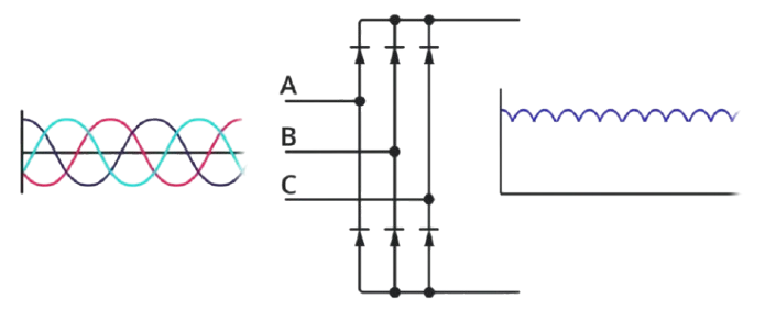
Figure 2. Rectifier
DC Link
After rectification, the current passes through the DC link, also known as the intermediate circuit. This stage plays a role in preparing the DC power for the inverter. The DC link typically includes capacitors (for energy storage) and inductors (for current smoothing). The capacitors absorb energy and release it steadily, helping to maintain a consistent voltage level. Meanwhile, inductors work to smooth out any fluctuations or ripples in the current. Together, they act as a filter, reducing electrical noise and suppressing voltage spikes that could otherwise damage downstream components. The result is a clean, stable DC voltage, a prerequisite for precise motor control in the next stage.

Figure 3. DC Link
Inverter
The inverter is the heart of the VFD's output stage. It converts the conditioned DC power from the DC link back into AC power but not just any AC. This time, it’s AC with variable frequency and voltage, precisely controlled to suit the motor’s operational needs. This transformation is accomplished using Insulated Gate Bipolar Transistors (IGBTs), high-speed electronic switches that can turn on and off thousands of times per second. The inverter utilizes a technique called Pulse Width Modulation (PWM), where it rapidly switches the DC on and off to produce a sequence of voltage pulses. These pulses are carefully timed and shaped to mimic a sinusoidal AC waveform. By adjusting the width and timing of these pulses, the inverter can control both the frequency (which dictates motor speed) and the voltage (which affects torque). This gives the VFD the ability to dynamically control motor behavior, from a gentle start-up to full-speed operation or even rapid deceleration.

Figure 4. Inverter
Control Unit
Overseeing the entire operation is the control unit, the intelligent processor that acts as the VFD’s brain. Typically built around a microcontroller or a digital signal processor (DSP), this unit continuously monitors both the internal conditions of the VFD and the external performance of the motor. The control unit processes inputs, system settings, and feedback signals such as motor speed, torque demand, temperature, and current draw. It then adjusts the inverter’s output to maintain optimal motor performance. This means the motor gets just the right amount of power for the task at hand, improving both energy efficiency and system longevity. The control unit handles protective functions, such as detecting overcurrent, overheating, or undervoltage conditions. If a fault is detected, it can shut down the drive or trigger alarms to protect both the VFD and the motor. Many control units also include communication ports (like Modbus, Profibus, or Ethernet) to allow integration with PLCs, HMIs, or building automation systems, enabling centralized control and monitoring.

Figure 5. Control Unit
Types of VFDs
Voltage-Source Inverter (VSI) Drives
Voltage-Source Inverter (VSI) drives are the most commonly used type of Variable Frequency Drive (VFD) in industrial and commercial applications. These drives operate by first converting the incoming AC (alternating current) supply into DC (direct current) using a diode-based rectifier. The DC power is then smoothed and stored in a capacitor bank, which acts as an energy reservoir. Finally, the stored DC is converted back into AC with variable frequency and voltage through an inverter, which typically uses Insulated Gate Bipolar Transistors (IGBTs) for efficient switching. The resulting variable-frequency AC output allows for precise control over the speed and torque of AC motors. VSI drives are highly versatile and are capable of driving multiple motors simultaneously, making them an attractive choice for general-purpose motor control in industries ranging from manufacturing to HVAC systems.
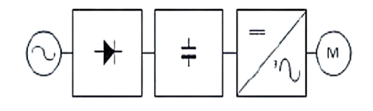
Figure 6. Voltage-Source Inverter (VSI) Drives
Advantages
• Wide Speed Range: VSI drives provide effective motor control across a broad range of speeds, making them suitable for both high-speed and low-speed applications.
• Simplicity and Cost-Effectiveness: Their relatively simple design and use of standard electronic components make VSI drives more affordable compared to other types of drives, such as Current-Source Inverter (CSI) drives or regenerative drives.
• Multi-Motor Control: One of the benefits of VSI drives is their ability to control multiple motors from a single drive, provided that the motors have similar load profiles. This makes them efficient in systems with synchronized operations, such as conveyor belts or fans.
Disadvantages
• Poor Power Factor at Low Speeds: At lower motor speeds, VSI drives tend to draw a distorted current waveform from the supply, resulting in a reduced power factor. This inefficiency can lead to higher energy costs and potential issues with utility compliance.
• Harmonic Distortion: The switching action of the inverter generates harmonic currents that can interfere with other sensitive equipment on the electrical network. Without proper filtering, this distortion can reduce the overall power quality and affect system reliability.
• No Regenerative Braking: Standard VSI drives do not have the capability to return energy to the power source during braking. This energy is dissipated as heat through braking resistors, leading to energy wastage. For applications requiring energy recovery, additional regenerative units must be incorporated, increasing complexity and cost.
Current-Source Inverter (CSI) Drives
Current-Source Inverter (CSI) drives are a specialized type of Variable Frequency Drive (VFD) that control motor performance by regulating current rather than voltage. These drives convert AC input into DC using Silicon-Controlled Rectifiers (SCRs), then smooth the DC current through large inductors. The filtered current is inverted back into AC by another set of SCRs, supplying the motor with a constant current. This approach provides stable torque, making CSI drives well-suited for high-inertia loads and heavy-duty applications like large compressors, pumps, and conveyors. A key advantage is their built-in regenerative braking capability, which returns energy to the power source during deceleration without additional hardware. However, CSI drives are bulkier and more expensive than other drive types due to their large inductors and complex control requirements. Their size and engineering demands limit their use in compact environments, but they remain a strong choice for high-power systems requiring robust and efficient motor control.
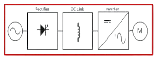
Figure 7. Current-Source Inverter (CSI) Drives
Advantages
• Excellent for High-Power Systems: CSI drives are well-suited for applications involving large motors and mechanical loads, where consistent torque and rugged performance are needed.
• Energy Regeneration: Unlike standard VSI drives, CSI drives can feed energy back into the power grid during braking. This feature improves energy efficiency and reduces operational costs, especially in applications with frequent deceleration.
• Smooth Current Output: The use of large inductors allows CSI drives to deliver a relatively ripple-free current, which minimizes motor heating and extends motor life, under demanding operating conditions.
Disadvantages
• Bulky and Expensive: Due to the need for large passive components (such as inductors and filters), CSI drives tend to be physically larger and more expensive than their voltage-source counterparts. This makes them less practical for small-scale or space-constrained installations.
• Single-Motor Operation Only: CSI drives are designed to supply a single, constant current path. As such, they are not suited for operating multiple motors from one drive, limiting their flexibility in multi-motor systems.
• Low-Speed Performance Issues: While they excel at high-power and constant torque applications, CSI drives may suffer from reduced precision and control at very low speeds, making them less ideal for applications requiring fine speed modulation.
Pulse Width Modulation (PWM) Drives
Pulse Width Modulation (PWM) drives are an advanced type of Voltage-Source Inverter (VSI) drive that use high-speed switching typically with Insulated Gate Bipolar Transistors (IGBTs) to generate precisely timed voltage pulses. These pulses simulate a near-sinusoidal AC waveform, offering smooth motor operation and reducing issues like torque ripple and vibration common in basic inverters. By controlling voltage and frequency with precision, PWM drives improve dynamic motor response and efficiency, making them ideal for applications such as robotics, CNC machines, and HVAC systems. They also support a wide range of motor types, including induction, synchronous, and permanent magnet motors. However, their benefits come with added complexity. PWM drives require advanced control electronics, better cooling systems, and additional filtering to handle the high-frequency switching harmonics. While more expensive than simpler drive systems, PWM drives provide excellent performance, energy efficiency, and flexibility for demanding motor control applications.

Figure 8. Pulse Width Modulation (PWM) Drives
Advantages
• High Efficiency: PWM drives are designed for energy-efficient operation, minimizing power losses through optimized switching and effective voltage control. This translates to lower operational costs over time.
• Smooth Motor Performance: By simulating a nearly sinusoidal AC waveform, PWM drives provide smooth torque and speed control, improving motor behavior and extending equipment lifespan.
• Supports Various Motor Types: The versatility of PWM technology makes these drives compatible with a wide range of motor technologies, providing flexibility in both new installations and retrofit applications.
Disadvantages
• More Components Required: PWM drives rely on additional components such as high-speed switches, control circuits, filters, and heat sinks, all of which increase the system's physical complexity and potential points of failure.
• Higher Cost and Complexity: The advanced electronics and control algorithms used in PWM drives lead to a higher initial cost and more intricate setup requirements. Skilled personnel may be needed for installation, tuning, and maintenance.
Matrix Converters
Matrix converters represent a modern and innovative approach to AC motor control, offering different architecture compared to traditional Variable Frequency Drives (VFDs). Unlike conventional drives, which rely on a two-stage process involving a rectifier (AC to DC) followed by an inverter (DC to variable AC), matrix converters eliminate the need for intermediate DC conversion entirely. Instead, a matrix converter uses an array or "matrix" of bidirectional switches to directly convert fixed-frequency, fixed-voltage AC input into variable-frequency, variable-voltage AC output. These switches adjust the connection between the input and output phases, synthesizing the desired waveform with high precision. Typically composed of Insulated Gate Bipolar Transistors (IGBTs) or similar high-speed switching devices, matrix converters rely on sophisticated control algorithms to ensure smooth, efficient, and accurate power conversion.
Advantages
• Compact Design: By eliminating the need for a DC link, matrix converters reduce the overall size and weight of the drive system. This makes them highly attractive in applications where space is at a premium.
• High-Quality Output: Matrix converters produce sinusoidal input and output waveforms with minimal harmonic distortion, contributing to better motor performance and extended equipment life.
• Bidirectional Power Flow: These converters naturally support regenerative braking, allowing energy to flow back into the power supply without the need for additional components, improving overall system efficiency.
• No DC Link Components: The absence of electrolytic capacitors increases reliability, particularly in harsh environments, and simplifies maintenance requirements.
Disadvantages
• High System Complexity: The control algorithms and switching strategies required for safe and efficient operation of matrix converters are highly complex, demanding advanced microcontrollers and processing capabilities.
• Expensive Components: The need for fast, reliable, and bidirectional switching devices increases the cost of matrix converters compared to conventional VFDs.
• Limited Commercial Availability: Due to the technical challenges and higher costs, matrix converters are not as widely available or supported as VSI or PWM drives, making them less practical for general-purpose use.
• Sensitive to Input Conditions: Matrix converters are more susceptible to input voltage disturbances, which can impact performance and require additional protection and filtering in unstable power environments.
Flux Vector Drives
Flux Vector Drives, also known as Vector Control or Field-Oriented Control (FOC) drives, provide precise control of AC motor speed and torque. Unlike standard VFDs, they adjust magnetic flux and torque-producing current independently by analyzing voltage and current phase relationships. Using vector mathematics, they control torque directly even at very low speeds making them ideal for applications requiring stability and accuracy. They use either sensor-based feedback (via encoders or resolvers) or sensorless algorithms to estimate motor position. Common in elevators, cranes, and manufacturing, flux vector drives offer smooth, responsive performance under varying loads, but require more complex setup and higher cost.
Advantages
• Precise Torque and Speed Control: Flux vector drives excel at maintaining consistent torque, even at very low speeds, making them ideal for lifting, positioning, and tensioning applications.
• Fast Dynamic Response: The vector control method allows for rapid adjustments in motor output in response to load variations, improving process stability and equipment safety.
• Versatility in Feedback Options: Whether using sensors for precision or sensorless algorithms for simpler setups, flux vector drives can be tailored to suit a wide range of performance and budget requirements.
• Improved Efficiency and Performance: Compared to scalar-controlled drives, flux vector drives offer better overall efficiency and smoother motor operation, reducing mechanical stress and extending motor life.
Disadvantages
• Higher Cost and Complexity: The advanced control algorithms and optional feedback sensors increase the cost of flux vector drives, as well as the complexity of installation and tuning.
• Requires Careful Configuration: Achieving optimal performance requires precise tuning of drive parameters, and sometimes commissioning by experienced technicians.
• Sensor Dependency in Some Applications: While sensorless systems are becoming more capable, certain high-precision or low-speed applications still require physical sensors, which adds to maintenance and system complexity.
How a VFD Works?

Figure 9. How a VFD Works?
A VFD works by adjusting both the frequency and voltage supplied to a motor. This is what allows it to control motor speed and torque with accuracy.
1. AC Input
The process begins with the VFD receiving three-phase alternating current (AC) power, typically at 60 Hz, directly from the electrical grid. This is the standard power format used in most industrial and commercial settings. The VFD must convert this fixed-frequency input into a form the motor can use at various speeds.
2. Rectification
Next, the incoming AC power is passed through a rectifier circuit. The rectifier is typically made up of diodes or thyristors, which serve to convert the alternating current into direct current (DC). However, this output is not smooth, it's a pulsating DC signal with ripples that must be filtered before use.
3. DC Link (Intermediate Circuit)
The pulsating DC then flows into what’s called the DC link or DC bus. This part of the VFD includes capacitors and sometimes inductors, which act as filters. Their job is to smooth out the ripples in the DC signal, producing a more stable and continuous DC voltage. This stage is important because any instability here would affect the performance of the inverter stage that follows.
4. Inversion
Now comes the core of the VFD: the inverter. The inverter consists of high-speed electronic switches, usually Insulated Gate Bipolar Transistors (IGBTs). These switches turn on and off in rapid succession to simulate an AC waveform using a technique called Pulse Width Modulation (PWM). By adjusting the timing and duration of the pulses, the inverter can create an output with a variable frequency and voltage, perfectly tailored to the motor’s required operating conditions.
5. Output to Motor
The resulting signal is a synthetic AC output with both adjustable frequency (how fast the voltage cycles) and amplitude (how strong the voltage is). This custom AC waveform is what is ultimately delivered to the motor. By changing the frequency, the VFD controls motor speed. By adjusting the voltage, it controls torque. The output is dynamic, allowing the motor to accelerate smoothly, run at optimal efficiency, and avoid mechanical stress.
To ensure the motor operates efficiently, the VFD maintains a constant volts-per-hertz (V/Hz) ratio. This ratio preserves the magnetic flux within the motor, which is need for maintaining consistent torque output. For instance, if a motor is designed to operate at 430 volts and 60 Hz, the V/Hz ratio is approximately 7.2. If the frequency is lowered to 30 Hz, the VFD correspondingly reduces the voltage to around 215 V to maintain that same ratio. Deviations from this ratio can result in excessive heat, reduced torque, or erratic motor behavior.
How VFDs Control Motor Speed?
Variable Frequency Drives (VFDs) are devices that regulate the speed and torque of electric motors by controlling the frequency and voltage supplied to the motor. Understanding how VFDs work starts with a look at the relationship between motor speed and electrical frequency. Motor speed is determined by two key factors: the frequency of the power supply and the number of magnetic poles in the motor. The relationship can be described by this formula:
RPM = (Frequency × 120) / Number of Poles
For example, a motor with 2 magnetic poles operating at a standard frequency of 60 Hz will rotate at:
RPM = (60 × 120) / 2 = 3,600 RPM
This means that by adjusting the frequency of the power supply, we can directly control the motor's speed. That’s exactly what a VFD does, it varies the frequency and voltage sent to the motor, allowing precise speed control across a wide range. This ability to fine-tune motor speed is valuable in applications where loads fluctuate, such as in pumping systems, HVAC units, conveyors, and material handling equipment. In these scenarios, running a motor at full speed all the time isn’t efficient or necessary. VFDs allow the motor to ramp up, slow down, or maintain just the right speed to match the actual demand. Beyond just speed control, VFDs offer energy savings. Since power consumption increases with motor speed, reducing speed even slightly can lead to substantial reductions in energy use. This not only cuts down on operating costs but also extends the life of mechanical components by reducing wear and tear caused by unnecessary high-speed operation.
Benefits of Using VFDs
Energy Savings
One of the most advantages of using a Variable Frequency Drive (VFD) lies in its remarkable potential for energy conservation. By adjusting the motor speed to precisely match the actual load requirements, VFDs can reduce energy consumption, especially in applications where the load demand fluctuates. In centrifugal systems such as fans, pumps, and blowers, a modest reduction in motor speed can yield disproportionately large energy savings. For example, a 20% decrease in speed can lead to nearly a 50% reduction in energy usage due to the cube law relationship between speed and power in such systems. This dramatic efficiency not only translates into substantial cost savings on electricity but also supports broader sustainability initiatives by lowering the facility’s overall carbon emissions and environmental impact. Over time, the cumulative effect of these savings can contribute to a more competitive and environmentally responsible operation.
Soft Start Capability
Unlike traditional across-the-line starters that instantly deliver full voltage to motors, often causing a sudden mechanical jolt and a spike in current, VFDs offer a refined alternative through their built-in “soft start” functionality. This feature allows for a gradual ramp-up of motor speed and torque during startup, thereby reducing inrush current and mechanical stress. The controlled acceleration not only prevents undue strain on the motor but also minimizes wear on belts, gears, and other mechanical components. By easing the burden on the electrical system during startup, VFDs help maintain power quality and reduce the likelihood of voltage dips or disturbances, particularly in facilities with sensitive equipment or tight power tolerances. Over time, this gentle handling of machinery contributes to longer equipment life, fewer maintenance issues, and greater overall reliability.
Reduced Maintenance Needs
By facilitating smooth acceleration and deceleration, VFDs greatly reduce mechanical and thermal stress on motors and associated equipment. Traditional motor starts and stops can introduce shock loads and sudden changes in torque, which contribute to premature wear on components such as bearings, couplings, belts, and shafts. With a VFD, these transitions are managed with precision, leading to less wear and tear over time. This translates directly into lower maintenance costs, as components last longer and require less frequent servicing. The predictable and consistent operation made possible by VFDs helps reduce the occurrence of unplanned downtime. The result is not only a reduction in repair costs but also improved productivity and equipment availability.
Improved Power Factor
VFDs can also contribute to a more efficient and balanced electrical system by improving the power factor. In conventional motor systems, especially those running at partial loads, a poor power factor can lead to excessive reactive power consumption, increasing demand charges from utility providers and reducing the overall efficiency of the electrical network. VFDs, however, draw power in a more controlled manner and can maintain a high power factor even at varying load conditions. In many installations, this eliminates the need for separate power factor correction equipment, simplifying the system design and reducing capital and maintenance expenses. Maintaining a high power factor improves voltage stability across the power distribution system, which can enhance the performance and longevity of other connected equipment.
Enhanced Product Quality
Precision and repeatability are good in many industrial processes, and VFDs offer unparalleled control over motor speed and torque, allowing for meticulous fine-tuning of operations. This level of control ensures that process parameters such as mixing times, conveyor speeds, and extrusion pressures remain consistent, even under varying load or environmental conditions. The result is a noticeable improvement in product uniformity, reduced waste, and fewer rejected batches. For industries where quality is tightly regulated, such as pharmaceuticals, food processing, and electronics manufacturing, this consistency is important. VFDs help maintain high standards of production by delivering dependable and precise control, even in the most demanding applications.
Versatility and Adaptability
One of the standout features of VFDs is their exceptional versatility across a broad range of applications. Whether used in HVAC systems, water treatment plants, material handling, or complex automation lines, VFDs can adapt to a wide array of motor-driven systems with varying operational demands. They can automatically adjust to changing loads, accommodate environmental variables, and integrate seamlessly with programmable logic controllers (PLCs) and other industrial control systems. With customizable parameters and multiple communication protocols, VFDs are well-suited for Industry 4.0 and smart factory environments. Their flexibility not only improves operational efficiency but also allows facilities to respond quickly to changing production requirements without costly overhauls or equipment replacements.
Where VFDs are Used?
HVAC Systems
Variable Frequency Drives (VFDs) are widely used in Heating, Ventilation, and Air Conditioning (HVAC) systems to optimize energy use. By adjusting the speed of fans, blowers, and pumps in response to temperature changes or occupancy levels, VFDs help maintain comfort while reducing energy consumption and wear on equipment.
Water and Wastewater Systems
In municipal and industrial water systems, VFDs control pump speeds based on flow and pressure demands. This dynamic control reduces water hammer and pressure surges, extends equipment life, and lowers operational costs by avoiding unnecessary energy use.
Manufacturing and Industrial Automation
In manufacturing settings, VFDs are important for coordinating the speed of conveyors, mixers, and rotating tools. This ensures consistent production rates, improves product quality, and allows for quick adjustments during process changes or product line shifts.
Plastics and Textile Industries
Precision is key in plastics and textiles production. VFDs help maintain consistent tension and speed during processes like extrusion, weaving, or spinning. This improves material uniformity, reduces scrap, and allows for greater flexibility in handling different materials or product specifications.
Smart Factories and Industry 4.0
Modern VFDs often feature Ethernet or other industrial network connectivity, enabling seamless integration into smart factory ecosystems. They support remote monitoring, diagnostics, and predictive maintenance, enhancing automation and minimizing downtime in advanced manufacturing environments.
Elevators and Hoists
VFDs provide precise motor control in elevator systems and hoisting equipment. By regulating acceleration, deceleration, and speed, they ensure smooth starts and stops, improving passenger comfort and enabling accurate load handling in industrial lifting operations.
Mining and Milling Operations
Mining and milling involve variable loads and harsh conditions. VFDs adapt equipment speed to match the density or consistency of the material being processed. This optimizes throughput, reduces mechanical stress, and improves overall efficiency and safety.
Laboratory Equipment
In scientific and medical laboratories, equipment like centrifuges rely on VFDs for precise speed control. Maintaining consistent rotational speeds is great for accurate, repeatable results in experiments and diagnostic procedures.
Conclusion
Variable Frequency Drives have become important in modern motor control, offering precise speed regulation, enhanced efficiency, and reduced mechanical stress. By understanding the components, types, operational principles, and applications of VFDs, you can make informed decisions for optimizing performance and energy usage in motor-driven systems. Whether in heavy industry, infrastructure, or advanced automation, VFDs serve as a versatile, intelligent solution to meet evolving demands in motion control and system reliability.
About us
ALLELCO LIMITED
Read more
Quick inquiry
Please send an inquiry, we will respond immediately.
Frequently Asked Questions [FAQ]
1. What is the difference between VFD and VSD?
A VFD (Variable Frequency Drive) specifically controls the speed of AC motors by adjusting the frequency and voltage of the power supplied, while a VSD (Variable Speed Drive) is a broader term that includes all types of speed control systems—both for AC and DC motors. So, all VFDs are VSDs, but not all VSDs are VFDs. VSD can include DC drives, mechanical gear systems, and other electronic controls, whereas VFD refers only to the electronic control of AC motor speed via frequency variation.
2. What is the disadvantage of VFD drive?
One key disadvantage of a VFD is the potential for generating electrical noise and harmonics, which can interfere with nearby equipment and reduce power quality. VFDs also add complexity to the system, require careful setup, and can increase maintenance needs. Without proper motor insulation or filters, the high-speed switching of VFDs can cause voltage spikes that stress motor windings, possibly reducing motor life over time.
3. Can a VFD destroy a motor?
Yes, a VFD can damage or destroy a motor if it’s not set up correctly. Fast switching transients and high-frequency voltage spikes from the VFD can cause insulation breakdown in motor windings, especially in older or non-inverter-rated motors. Running a motor outside its safe speed range or without adequate cooling at low speeds can also overheat and degrade it. Proper grounding, filtering, and programming are needed to prevent such issues.
4. How efficient is a VFD?
VFDs are generally very efficient, typically offering 95% to 98% efficiency during operation. They help improve overall system efficiency by allowing motors to run only at the speeds required for the task, which reduces energy waste compared to running at full speed constantly. However, small energy losses still occur due to internal switching and heat generation within the VFD itself.
5. Is VFD output AC or DC?
The output of a VFD is AC. Inside the VFD, incoming AC power is first converted to DC through a rectifier, then filtered and inverted back into a variable-frequency AC output. This variable AC allows the motor to change its speed smoothly. So, although DC is used internally, the final output sent to the motor is always AC.

What Is a TRIAC and How It Controls AC Power
on April 8th
All About the EPF6024AQC240-2 FPGA Chip
on April 7th
Popular Posts
-

Complex Instruction Set Computers: How They Changed Computing?
on April 18th 147749
-

USB-C Pinout and Features
on April 18th 111919
-

Using Xilinx Unified Simulation Primitives: A Comprehensive Guide to FPGA Design and Simulation
on April 18th 111349
-

Power Supply Voltages in Electronics: Meaning of VCC, VDD, VEE, VSS, and GND
on April 18th 83714
-

RJ45 Connector Guide: Pinout, Wiring, Cable Types, and Uses
on January 1th 79502
-

The Ultimate Guide to Wire Color Codes in Modern Electrical Systems
The way our electrical systems use colors isn’t just for looks. Each wire color now indicates a specific function, making it easier to identify and handle electrical components correctly during ins...on January 1th 66872
-

Quality (Q) Factor: Equations and Applications
The quality factor, or 'Q', is important when checking how well inductors and resonators work in electronic systems that use radio frequencies (RF). 'Q' measures how well a circuit minimizes energy...on January 1th 63005
-

Purge Valve Guide: Function, Symptoms, Testing, and Replacement for Optimal Engine Performance
The purge valve is a key part of a car’s system that helps keep the air clean by managing fuel vapors before they can escape into the atmosphere. This not only helps the environment by reducing pol...on January 1th 62950
-

Achieving Peak Performance with the Maximum Power Transfer Theorem
The Maximum Power Transfer Theorem explains how energy from a source, such as a battery or generator, flows to a connected load. It shows the exact condition where the load receives the most power....on January 1th 54077
-

A23 Battery Specifications and Compatibility
The A23 battery is a small, cylinder-shaped battery with high voltage. Also called 23A, 23AE, or MN21, it runs at 12 volts and much higher than AA or AAA batteries. Its special design make...on January 1th 52091
HOT Part Number
-

BD9B100MUV-E2
Rohm Semiconductor
IC REG BUCK ADJ 1A 16VQFN
UPD70F3539AF5A9-PN7-Q-A
Renesas Electronics America Inc
IC MICROCONTROLLER
18081A621JAT2A
KYOCERA AVX
CAP CER 620PF 100V NP0 1808
FDN340P
onsemi
MOSFET P-CH 20V 2A SUPERSOT3
70231-101
Amphenol ICC (FCI)
CONN RCPT BLADE PWR 8POS EDGE MT
MPSW42RLRAG
onsemi
TRANS NPN 300V 0.5A TO92
MC7824BT
onsemi
IC REG LINEAR 24V 1A TO220AB
AD8009ARZ-REEL
Analog Devices Inc.
IC OPAMP CFA 1 CIRCUIT 8SOIC
LT1815CS5#TRPBF
Analog Devices Inc.
IC OPAMP VFB 1 CIRCUIT TSOT23-5
DG411DYZ
Renesas Electronics America Inc
IC SWITCH SPST-NCX4 35OHM 16SOIC
VFT2060C-M3/4W
Vishay General Semiconductor - Diodes Division
DIODE SCHOTTKY 20A 60V ITO-220AB
TSX562AIYST
STMicroelectronics
IC CMOS 2 CIRCUIT 8MINISO
MR256D08BMA45
Everspin Technologies Inc.
IC RAM 256KBIT PARALLEL 48FBGA
VSC3312YYP-01
Microchip Technology
IC SWITCH 16X16 6.5GBPS 196FCBGA
XC68HC908GP20CFB
Motorola
TSG 8BIT20K FLASH
CSR8811A08-ICXR-R
Qualcomm
IC RF TXRX+MCU BLUETOOTH
MPSW05
onsemi
TRANS NPN 60V 0.5A TO92
1N4055R
Solid State Inc.
DIODE GEN PURP REV 900V 275A DO9 -

ASX342ATSC00XPED0-DP
onsemi
IMAGE SENSOR VGA 1/4 CIS SOC
0433.125NR
Littelfuse Inc.
FUSE BOARD MNT 125MA 125VAC/VDC
1SMA5941BT3G
onsemi
DIODE ZENER 47V 1.5W SMA
DCP010512BP-U/700
Texas Instruments
DC DC CONVERTER 12V 1W
1-1734344-1
TE Connectivity AMP Connectors
CONN D-SUB HD RCPT 15P R/A SLDR
KSD1621STF
onsemi
TRANS NPN 25V 2A SOT89-3
BQ24161RGET
Texas Instruments
IC BATT CHG LI-ION 1CELL 24VQFN
BTA26-600BW
STMicroelectronics
TRIAC ALTERNISTOR 600V 25A TOP3
NCP1239DD65R2G
onsemi
IC OFFLINE SWITCH FLYBACK 7SOIC
TMS320TCI6482BZTZA
Texas Instruments
TMS320 - DIGITAL SIGNAL PROCESSO
BQ20Z90DBTR-V150
Texas Instruments
IC GAS GAUGE LI-ION 30TSSOP
PCMB104T-1R0MT
Susumu
FIXED IND 1UH 18A 3.3 MOHM SMD
CY29942AXCT
Infineon Technologies
IC CLK BUFFER 1:18 200MHZ 32TQFP
CC0402KRX7R9BB561
YAGEO
CAP CER 560PF 50V X7R 0402
STPS20M60SG-TR
STMicroelectronics
DIODE SCHOTTKY 60V 20A D2PAK
AT25010N-10SC-2.7
Microchip Technology
IC EEPROM 1KBIT SPI 3MHZ 8SOIC
04023A1R0CAT4A
KYOCERA AVX
CAP CER 1PF 25V C0G/NP0 0402
ISL6327IRZ
Intersil
SWITCHING CONTROLLER, VOLTAGE-MO -

LQW18AN75NG0ZD
Murata Electronics
FIXED IND
DFA100BA160
SanRex Corporation
DIODE MODULE 1600V 100A
BAR46AFILM
STMicroelectronics
DIODE ARRAY SCHOTTKY 100V SOT23
MAX825SEUK
Analog Devices Inc./Maxim Integrated
IC SUPERVISOR MPU
MMST2222A-7-F
Diodes Incorporated
TRANS NPN 40V 0.6A SOT323
FODM8801AR2
onsemi
OPTOISO 3.75KV TRANS 4-MINI-FLAT
FJV1845FMTF
Fairchild Semiconductor
SMALL SIGNAL BIPOLAR TRANSISTOR,
EVK105RH5R1JW-F
Taiyo Yuden
CAP CER 5.1PF 16V R2H 0402
6651170-3
TE Connectivity AMP Connectors
CONN EDGE DUAL FMALE 4POS 0.508
KSZ8893FQLI-FX
Microchip Technology
IC SWITCH ETH 3PORT 128QFP
170M6340
Eaton - Bussmann Electrical Division
FUSE SQUARE 400A 1.3KVAC RECT
BCM20741A2KFB1G
Broadcom Limited
SINGLE-CHIP BLUETOOTH
MAX3443EASA+
Analog Devices Inc./Maxim Integrated
IC TRANSCEIVER HALF 1/1 8SOIC
GRM0335C1H9R3DA01D
Murata Electronics
CAP CER 9.3PF 50V C0G/NP0 0201
TNY175PN
Power Integrations
11.5 W (85-265 VAC) 15 W (230 VA
742700726
Würth Elektronik
FERRITE CORE 278 OHM SOLID 4MM
DM74S20N
onsemi
IC GATE NAND 2CH 4-INP 14DIP
P4SMA56CA-E3/61
Vishay General Semiconductor - Diodes Division
TVS DIODE 47.8VWM 77VC DO214AC