Understanding the IR2110 MOSFET Driver
MOSFET drivers are requisite in modern electronics, bridging the gap between low-power control signals and the high-power demands of power MOSFETs. Among these, the IR2110 stands out as a versatile, high-performance driver, renowned for its ability to operate seamlessly in high-speed and high-voltage applications. Designed to function in both CMOS and TTL environments, the IR2110 is a key component in ensuring precise signal translation and efficient power management. This article digs into the IR2110’s core functionalities, highlights its design advantages for high-side and low-side switching, and explores its practical applications in power systems such as motor drives, renewable energy systems, and switching power supplies. The IR2110 offers reliability and adaptability that simplify system development while enhancing performance.Catalog

IR2110 MOSFET Driver Overview
The IR2110 is an advanced high-voltage driver IC tailored to manage high-side and low-side switches in bridge circuits, such as low-bridge and half-bridge configurations. This high-speed driver IC provides separate low and high-side outputs, facilitating compatibility with standard CMOS and LSTTL logic levels. Featuring robust HVIC and latch-immune CMOS technology, the IR2110 endures demanding operational environments, supporting a voltage range between 10V to 20V with a peak output current of 2.5A and a supply current of 340μA, making it suitable for a variety of high-power switching tasks. Proven design practices emphasize the balance between the performance and durability of these applications.
Industrially and in the automotive sectors, the IR2110 is preferred for its resilience in challenging conditions, ensuring stable performance amid power fluctuations. Practical insights show that incorporating this driver often reduces component failure rates, enhancing both the longevity and dependability of complex systems.
The IR2110’s high-speed capabilities are serious in applications requiring rapid and exact switching, such as renewable energy systems. In solar inverters, swift switching enhances energy conversion efficiency, pivotal for optimizing energy yield. As technology advances, the continuous adaptation of components like the IR2110 is required to meet new performance standards, emphasizing the role of innovation and strategic foresight in electronic design.
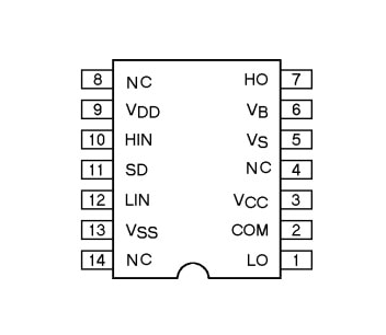
Pin Configuration
|
Pin Number |
Pin Name |
Description |
|
1 |
LO |
Low-side gate driver’s output pin. |
|
2 |
COM |
Return path for low-side configuration. |
|
3 |
VCC |
Power supply pin for the low side. |
|
4, 8, 14 |
NC |
Not connected pins. |
|
5 |
VS |
Return path floating-point pin for the high-side drive. |
|
6 |
VB |
Floating supply pin used for high-side drive. |
|
7 |
HO |
Output signal pin used for high-side MOSFET. |
|
9 |
VDD |
+5V power supply pin. Voltage must be 5V; using below 4V
may not provide the necessary result. |
|
10 |
HIN |
PWM signal input used for high-side drive. |
|
11 |
SD |
Shutdown pin used to automatically turn off the system. |
|
12 |
LIN |
PWM signal input for low-side drive. |
|
13 |
VSS |
Power supply GND pin. |
Features and Specs
|
Feature/Specification |
Details |
|
Number of Pins |
14 |
|
Package Types |
PDIP, SOIC |
|
dV/dt Immunity |
Yes |
|
Under Voltage Lockout |
Available for two channels |
|
Input Type |
Pull down CMOS Schmitt-triggered inputs |
|
Shutdown Logic |
Edge-triggered with cycle by cycle |
|
Propagation Delay |
Matched for both channels |
|
Input/Output Phase Relationship |
Outputs are within phase by inputs |
|
Logic Compatibility |
Compatible with 3.3 V logic |
|
Gate Drive Supply Range |
10 V – 20 V |
|
Logic Supply Range |
3.3 V – 20 V |
|
Ground Offset |
Logic & power ground is ±5 V |
|
Output Current |
2.5 A |
|
Voltage Supply Range |
10 V – 20 V |
|
Rise Time |
35 ns |
|
Fall Time |
25 ns |
|
Turn-On Delay Time (Max) |
120 ns |
|
Turn-Off Delay Time (Min) |
94 ns |
|
Operating Current Supply |
340 µA |
|
Equivalent MOSFET Drivers |
MIC4608, UCC27714, FAN7392 |
Build Efficient Circuits with the IR2110 MOSFET Driver
Within half-bridge configurations, the IR2110 ensures precise handling of both high-side and low-side MOSFETs. This IC is dominant in systems that demand meticulous power management and enhanced efficiency. Beyond its role, it reflects the user’s intent to harmonize power flow with operational demands.

Components and Associated Functions
The IR2110 MOSFET driver circuit incorporates diodes, capacitors, and the MOSFETs. These components form the backbone of a bootstrap circuit, capturing the essence of maintaining appropriate gate voltages. Their integration portrays the commitment to refining energy distribution.
• Bootstrap Circuit and Capacitor Dynamics: The bootstrap circuit serves as the heartbeat of efficient bridge setups, enabling capacitor charge-discharge cycles. This delicate balance of voltages is active for MOSFET gate functionality, transforming the notional design into operational reality. Experimentation in capacitor values based on specific circuit distinctions is an exploration of performance optimization.
• Rapid Switching Behavior: Diodes forge rapid discharge paths that bypass gate resistors, significantly shortening MOSFET turn-off intervals. This characteristic is prized in high-performance contexts, as it fulfills the need for swift transitions, resonating with the desire for speed in electronic communications.
• Gate-to-Source Resistors: Acting as silent guardians, gate-to-source resistors prevent accidental MOSFET triggering from noise or floating gate issues. Thoughtfully chosen and strategically placed, these resistors reinforce system integrity, mirroring the design philosophy that champions careful consideration of external influences.
Applications of the IR2110 MOSFET Driver
High-Speed Switching
The IR2110 is instrumental in boosting power efficiency during high-speed switching, mostly for motor drives, inverters, and systems demanding rapid responses. Its competence in managing swift switching operations minimizes energy loss, contributing to heightened efficiency. By skillfully employing this component, you report notable gains in system reliability and performance, especially in industrial environments where accuracy is highly valued.
Electrical Isolation
A remarkable attribute of the IR2110 is its strong electrical isolation, adept at shielding sensitive input circuits from potentially harmful high-power output voltages. This feature plays a major role in safeguarding fragile electronic parts from voltage surges and disturbances, thereby extending the system's operational life. You can frequently utilize this driver in your projects to enhance safety measures and lower long-term maintenance efforts.
Bridge Configurations
The IR2110 excels in handling both half-bridge and full-bridge setups, facilitating the smooth bidirectional power regulation that advanced electronics require. This flexibility supports an extensive array of applications, including propulsion systems in electric vehicles and complex consumer electronics. You can note that its versatility simplifies design processes significantly while maintaining competitive performance levels.
Motor Control Applications
In motor control applications, the IR2110 enables detailed modulation of motor speed and direction. Its rapid switching capacity allows for meticulous control, useful for applications like robotics that demand precise motor actions. Over the years, it has been observed that integrating this driver yields smooth operation and augments efficiency, aiding in the advancement of automation technologies.
Switching Power Supply Performance
In switching power supplies, the IR2110 plays a major role in reliable power management, ensuring stable power delivery across various contexts. Its role in power supply designs is associated with improved load regulation and efficiency. You can harness the IR2110's abilities can lead to superior performance outcomes and energy efficiency, highlighting its impact on contemporary power electronics.
Datasheet PDF
IR2110 Datasheets:
About us
ALLELCO LIMITED
Read more
Quick inquiry
Please send an inquiry, we will respond immediately.
Step-by-Step Guide to Amplifier Circuits Using TDA2050
on December 16th
BC556 Transistor: Complete Guide to Pinout, Specifications, Working, and Applications
on December 15th
Popular Posts
-

Complex Instruction Set Computers: How They Changed Computing?
on April 18th 147753
-

USB-C Pinout and Features
on April 18th 111927
-

Using Xilinx Unified Simulation Primitives: A Comprehensive Guide to FPGA Design and Simulation
on April 18th 111349
-

Power Supply Voltages in Electronics: Meaning of VCC, VDD, VEE, VSS, and GND
on April 18th 83714
-

RJ45 Connector Guide: Pinout, Wiring, Cable Types, and Uses
on January 1th 79504
-

The Ultimate Guide to Wire Color Codes in Modern Electrical Systems
The way our electrical systems use colors isn’t just for looks. Each wire color now indicates a specific function, making it easier to identify and handle electrical components correctly during ins...on January 1th 66872
-

Quality (Q) Factor: Equations and Applications
The quality factor, or 'Q', is important when checking how well inductors and resonators work in electronic systems that use radio frequencies (RF). 'Q' measures how well a circuit minimizes energy...on January 1th 63005
-

Purge Valve Guide: Function, Symptoms, Testing, and Replacement for Optimal Engine Performance
The purge valve is a key part of a car’s system that helps keep the air clean by managing fuel vapors before they can escape into the atmosphere. This not only helps the environment by reducing pol...on January 1th 62957
-

Achieving Peak Performance with the Maximum Power Transfer Theorem
The Maximum Power Transfer Theorem explains how energy from a source, such as a battery or generator, flows to a connected load. It shows the exact condition where the load receives the most power....on January 1th 54079
-

A23 Battery Specifications and Compatibility
The A23 battery is a small, cylinder-shaped battery with high voltage. Also called 23A, 23AE, or MN21, it runs at 12 volts and much higher than AA or AAA batteries. Its special design make...on January 1th 52093
HOT Part Number
-

RMPA0959
onsemi
IC RF AMP CELL 824-849MHZ 11LCC
RCLAMP0554S.TCT
Semtech Corporation
TVS DIODE 5VWM 15VC SOT23-6
CM453232-R47KL
Bourns Inc.
FIXED IND 470NH 545MA 320MOHM SM
744028002
Würth Elektronik
FIXED IND 2.2UH 1.3A 155MOHM SMD
MIC3809YMM
Microchip Technology
IC REG CTRLR MULT TOPOLOGY 8MSOP
AONS36302
Alpha & Omega Semiconductor Inc.
MOSFET N-CH 30V 146A 8DFN
SP3238EEA-L/TR
MaxLinear, Inc.
IC TRANSCEIVER FULL 5/3 28SSOP
BF5020WH6327
Infineon Technologies
N-CHANNEL POWER MOSFET
C1608X8R1H102M080AE
TDK Corporation
CAP CER 1000PF 50V X8R 0603
TPS71525QDCKRQ1
Texas Instruments
IC REG LINEAR 2.5V 50MA SC70-5
170M5444
Eaton - Bussmann Electrical Division
FUSE SQUARE 500A 1.3KVAC RECT
IHLP4040DZER220M1A
Vishay Dale
IHLP-4040DZ-1A 22 20% ER E3
C0603X181J1HACAUTO
KEMET
CAP CER 0603 180PF 100V ULTRA ST
PIC16F1575-E/JQ
Microchip Technology
IC MCU 8BIT 14KB FLASH 16UQFN
OPA4354AIPWR
Texas Instruments
IC CMOS 4 CIRCUIT 14TSSOP
P6SMB33A
Bourns Inc.
TVS DIODE 28.2VWM 45.7VC DO214AA
GCM1885C1H4R4CA16D
Murata Electronics
CAP CER 4.4PF 50V C0G/NP0 0603
R5F100LGAFB#10
Renesas Electronics America Inc
IC MCU 16BIT 128KB FLASH 64LFQFP -
TC621CCOA
Microchip Technology
THERMOSTAT PROG ACTIVE LOW 8SOIC
IRG4BC20UDPBF
International Rectifier
IGBT, 13A I(C), 600V V(BR)CES, N
MICROSMD175F-2
Littelfuse Inc.
PTC RESET FUSE 6V 1.75A 1210
AC0603KRX7R8BB222
YAGEO
CAP CER 2200PF 25V X7R 0603
1812AA150JAT1A\SB
KYOCERA AVX
CAP CER 15PF 1KV NP0 1812
SY10ELT22ZC
Microchip Technology
IC TRANSLTR UNIDIRECTIONAL 8SOIC
SCW03B-12
MEAN WELL USA Inc.
DC DC CONVERTER 12V 3W
A4840
Sensata-Crydom
SSR RELAY SPST-NO 40A 80-530V
TC4426AEOA
Microchip Technology
IC GATE DRVR LOW-SIDE 8SOIC
C1608NP01H470J080AA
TDK Corporation
CAP CER 47PF 50V NP0 0603
GRM1555C2A8R1DA01J
Murata Electronics
CAP CER 8.1PF 100V C0G/NP0 0402
INA330AIDGST
Texas Instruments
IC OPAMP GP 1 CIRCUIT 10VSSOP
12061C273KAT2A
KYOCERA AVX
CAP CER 0.027UF 100V X7R 1206
74LX1G70CTR
STMicroelectronics
IC BUF NON-INVERT 5.5V SOT323-5
CSNE151-204
Honeywell Sensing and Productivity Solutions
SENSOR CURRENT HALL 90A AC/DC
LF353DT
STMicroelectronics
IC OPAMP JFET 2 CIRCUIT 8SOIC
SMK316B7223KLHT
Taiyo Yuden
CAP CER 0.022UF 630V X7R 1206
R9G01612XX
Powerex Inc.
DIODE GP 1.6KV 1200A DO200AB -
FPF2300MPX
Fairchild Semiconductor
DUAL OUTPUT CURRENT LIMIT SWITCH
HZB6.8MWATL-E
Renesas Electronics America Inc
TVS DIODE 3.5VWM 3CMPAK
P0111MA 1AA3
STMicroelectronics
SCR 600V 800MA TO92-3
88E1545-A1-LKJ2C000
Marvell Semiconductor, Inc.
IC TXRX FULL/HALF 4/4 128LQFP
MAX809SN293D1T1G
onsemi
IC SUPERVISOR 1 CHANNEL SOT23-3
ICL3232IBZ-T
Renesas Electronics America Inc
IC TRANSCEIVER FULL 2/2 16SOIC
EP1K50FI484-2
Altera
LOADABLE PLD, 0.4NS PBGA484
FDMF6824C
onsemi
IC HALF BRIDGE DRIVER 50A 40PQFN
HVD144AKRF-E
Renesas Electronics America Inc
PLANAR PIN DIODE
MCD56-12IO1B
IXYS
MOD THYRISTOR/DIO 1200V TO-240AA
CD3275A0DRCR
Texas Instruments
PROTOTYPE
SN74ALS240ANSR
Texas Instruments
IC BUFFER INVERT 5.5V 20SO
9FG104EGLF
Renesas Electronics America Inc
IC FREQ TIMING GENERATOR 28TSSOP
MPC8548EVTAUJB
Freescale Semiconductor
MPU, 32-BIT, 1333MHZ, PBGA783
NCP1070STCT3G
onsemi
IC OFFLINE SWITCH FLYBACK SOT223
MIC4422YM
Microchip Technology
IC GATE DRVR LOW-SIDE 8SOIC
BU2510-E3/51
Vishay General Semiconductor - Diodes Division
BRIDGE RECT 1P 1KV 3.5A BU
GS8642Z36GB-167IV
GSI Technology Inc.
IC SRAM 72MBIT PARALLEL 119FPBGA