What Is a Transformer Core
You might have noticed how transformers quietly support almost every electrical system around you. At the center of all of them is the transformer core, guiding magnetic energy so voltage can change safely and efficiently. Understanding how transformer cores work helps you see why different designs exist and where each one fits best. From large power stations to everyday electronics, core shape, structure, and material all influence performance. This guide walks you through transformer core basics in a clear way, helping you connect how they work with where they’re actually used.Catalog
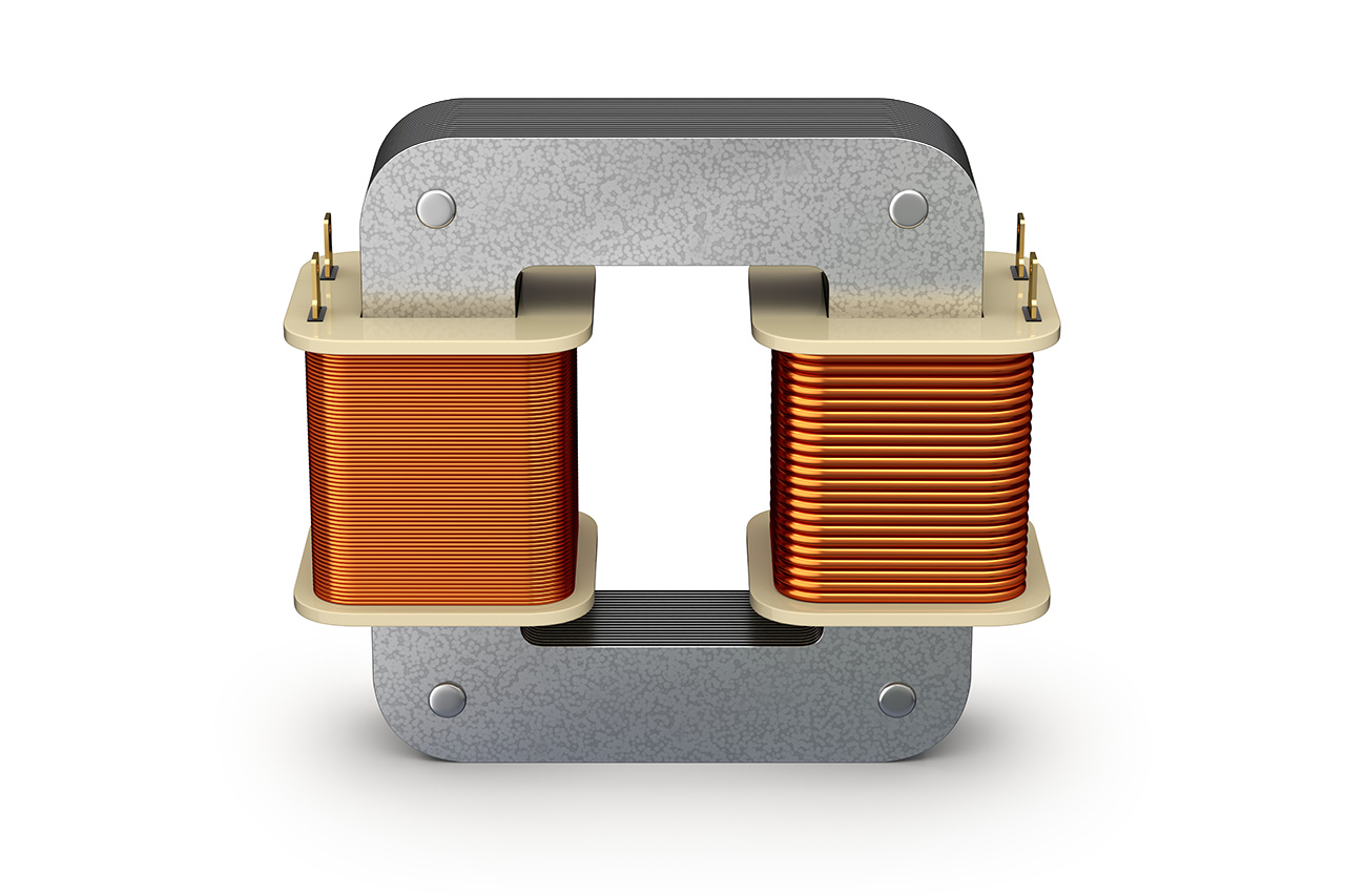
Figure 1. Transformer Core
What Is a Transformer Core
A transformer core is the magnetic structure inside a transformer that enables energy transfer between windings. It is usually made from ferromagnetic materials such as silicon steel, which allow magnetic flux to flow easily. The core provides a defined magnetic path that links the primary and secondary windings.
Its main function is to support magnetic coupling between windings. When alternating current flows through the primary winding, it creates a changing magnetic field that the core guides toward the secondary winding, allowing voltage transformation without direct electrical contact.
The core also serves a structural role by holding the windings in place and maintaining proper alignment. Through these magnetic and mechanical functions, the transformer core plays a central role in reliable transformer operation.
Parts of a Transformer Core
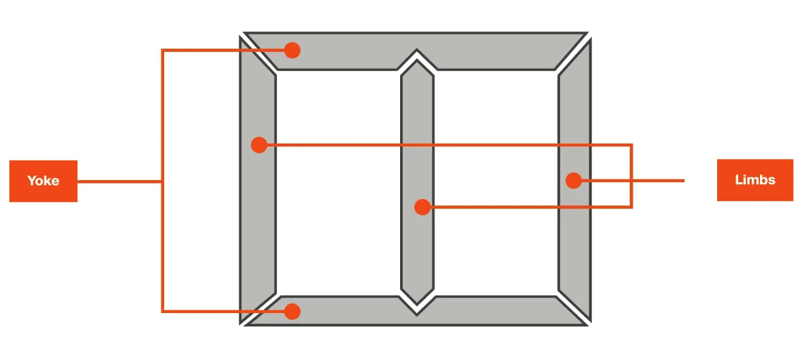
Figure 2. Parts of a Transformer Core
A transformer core consists of a few key parts that guide magnetic flux and support the windings. Together, these parts influence both the magnetic performance and overall efficiency of the transformer.
Core Limbs
Core limbs are the vertical sections of the transformer core around which the windings are placed. These sections carry most of the magnetic flux produced during operation. As current flows through the windings, the limbs provide a low-resistance path that allows the magnetic field to pass directly through the coils, supporting effective energy transfer between windings. Because the windings are mounted on the limbs, their size and shape also influence cooling, insulation spacing, and overall transformer layout.
Core Yokes
Core yokes are the horizontal sections of the core that connect the limbs and complete the magnetic circuit. Their main role is to provide a continuous return path for magnetic flux, ensuring that the field remains confined within the core structure rather than spreading into surrounding air. In addition to guiding flux, the yokes help hold the core together, contributing to mechanical strength and maintaining proper alignment between limbs during operation and handling.
How a Transformer Core Works

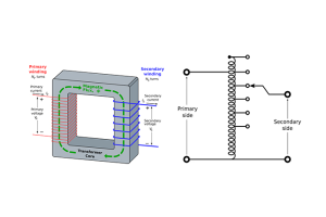
Figure 3. Magnetic Flux Flow in a Transformer Core
A transformer core functions by providing a defined path for magnetic flux produced by alternating current in the primary winding. When an alternating current flows through the primary winding, it generates a continuously changing magnetic field. This field becomes concentrated within the core because the core material offers much lower resistance to magnetic flux than the surrounding air.
The magnetic flux travels through the core and links both the primary and secondary windings. As this flux changes over time, it induces a voltage in the secondary winding. Through this process, electrical energy is transferred from the primary side to the secondary side without direct electrical contact. The presence of the core ensures that most of the magnetic field created by the primary winding reaches the secondary winding rather than dispersing outward.
By guiding magnetic flux along a controlled path, the transformer core helps maintain efficient coupling between windings and limits losses caused by stray magnetic fields. This controlled magnetic behavior allows voltage transformation to occur in a stable and predictable manner, forming the basis of transformer operation in practical electrical systems.
Common Transformer Core Types
Modern transformers use different core designs depending on application, efficiency requirements, and manufacturing needs. Core shape and construction influence magnetic performance, losses, and overall transformer behavior.
Core-Type vs Shell-Type Transformer Cores
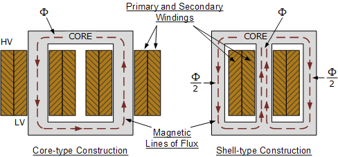
Figure 4. Core-Type and Shell-Type Transformer Cores
Core-type and shell-type transformers differ mainly in how the windings and core are arranged, which directly affects magnetic flux flow, material use, and overall losses.
In a core-type transformer, the windings are placed around the core limbs, and the magnetic flux flows through the core sections that support these windings. This arrangement creates a relatively open magnetic path and makes the windings more accessible. Because of this layout, core-type designs generally require less core material but slightly more winding material. They are commonly used in large power and distribution transformers, where ease of insulation, cooling, and maintenance is important.
In a shell-type transformer, the core surrounds the windings, enclosing them within the core structure. The magnetic flux is divided into multiple paths within the core, which helps keep it tightly contained. This reduces leakage flux and can lead to lower magnetic losses. Shell-type designs usually require more core material but less winding material. They are often chosen for distribution and special-purpose transformers where compact size, improved magnetic control, and reduced noise are preferred.
Three-, Four-, and Five-Limb Transformer Cores
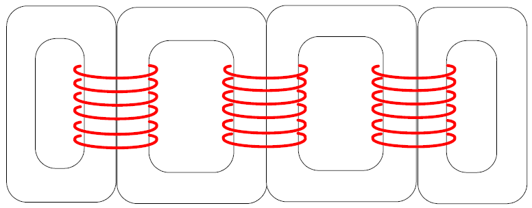
Figure 5. Three-, Four-, and Five-Limb Transformer Cores
The number of limbs in a transformer core directly affects how magnetic flux returns through the core during operation. Each limb provides a path for flux produced by the windings, and the overall limb arrangement determines how well this flux is contained within the core structure.
A three-limb transformer core is widely used in many three-phase transformers because it offers a compact and material-efficient design. In this configuration, each phase winding is placed on one limb, and the magnetic flux from the three phases shares common return paths through the core. This arrangement performs well under balanced operating conditions and is commonly selected for standard applications where simplicity and reduced core material are preferred.
In some operating conditions, however, the shared return paths in a three-limb core are not sufficient to fully contain all components of magnetic flux. Four-limb and five-limb transformer cores address this by adding one or two outer limbs that act as dedicated return paths. These additional limbs provide clearer routes for magnetic flux to circulate within the core, rather than spreading into surrounding structures.
By offering improved control of return flux, four- and five-limb designs help reduce stray magnetic fields, limit additional losses, and lower noise levels. For this reason, they are often used in transformer configurations where flux balance, thermal performance, or operating stability requires closer control of magnetic behavior.
Laminated Transformer Core
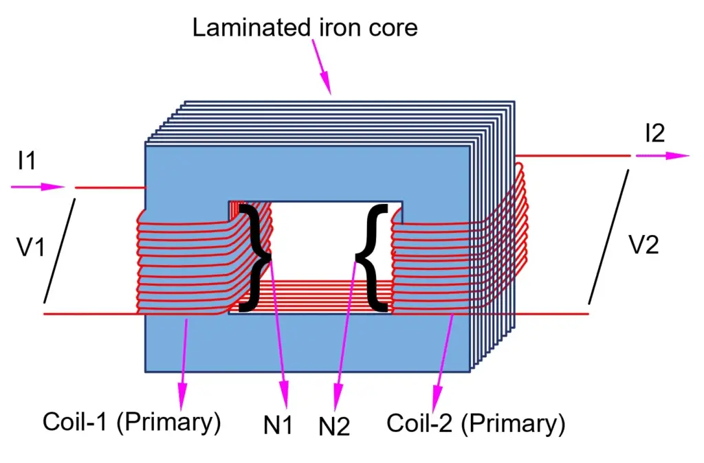
Figure 6. Laminated Transformer Core Structure
A laminated transformer core is constructed from thin sheets of electrical steel stacked together to form the core structure. Each sheet is electrically insulated from the next, which limits unwanted circulating currents within the core material. By reducing these currents, the laminated structure helps control heat buildup during operation and improves overall efficiency.
This type of core design is widely used in modern transformers because it provides a practical balance between energy efficiency, mechanical strength, and manufacturing cost. Laminated cores perform reliably across a wide range of power levels, which makes them suitable for both low-power applications and larger distribution or power transformers.
Distributed Gap Transformer Core
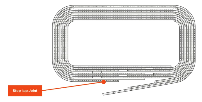
Figure 7. Distributed Gap Transformer Core
A distributed gap transformer core, often referred to as a wrapped core, is formed by shaping steel laminations into a continuous core structure rather than assembling them as stacked sections. This manufacturing method results in small gaps distributed throughout the core, rather than concentrated at specific joints.
The distributed gaps help control magnetic behavior by smoothing flux flow and limiting localized saturation. This design also contributes to lower operating noise and stable magnetic performance under normal load conditions. Distributed gap cores are commonly used in distribution transformers, where consistent operation, reliable performance, and reduced manufacturing cost are important design considerations.
Toroidal Transformer Core
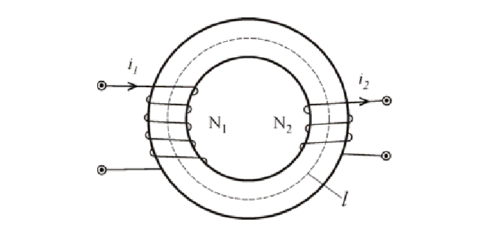
Figure 8. Toroidal Transformer Core
A toroidal transformer core has a ring-shaped structure with windings wrapped evenly around it. This design provides a very smooth magnetic path, which helps lower losses and reduce stray magnetic fields. Toroidal cores are often used in compact power supplies and electronic equipment, especially when quiet operation and small size are important.
Applications of Transformer Cores
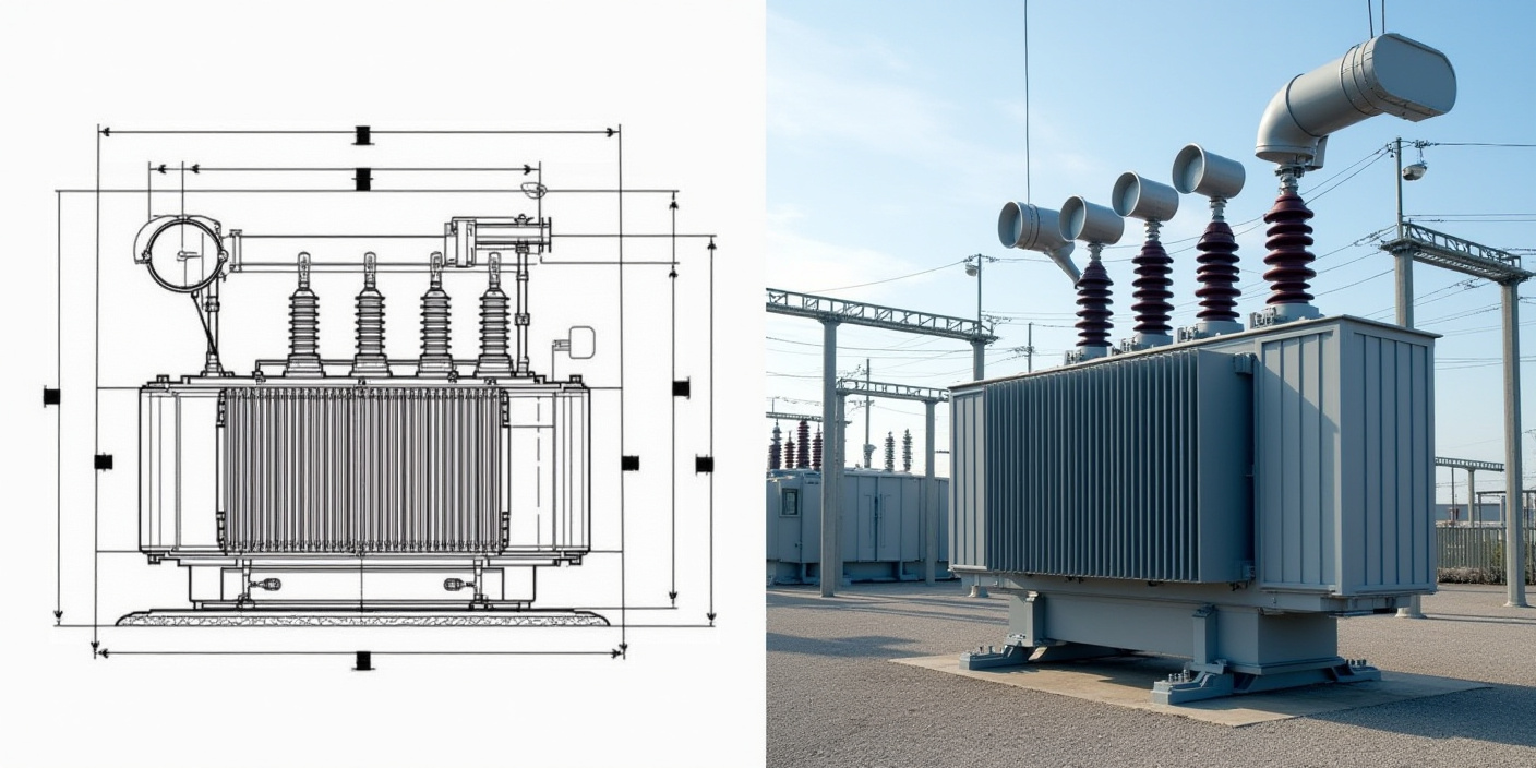
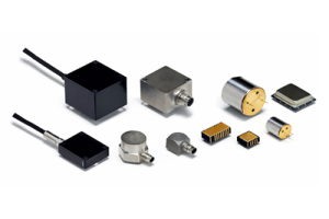
Figure 9. Power Transformer Applications
Transformer cores are used across a wide range of electrical systems, where they enable reliable energy transfer and voltage control under different operating conditions. Their design and material selection vary depending on system voltage, efficiency expectations, physical size limits, and environmental demands.
In power distribution networks, transformer cores are a central part of pole-mounted, pad-mounted, and ground-mounted transformers. These systems operate continuously and often at high voltage levels, so core designs are chosen to minimize losses, control heat, and ensure long service life. In substations, larger transformer cores support voltage conversion between transmission and distribution levels, where mechanical strength and stable magnetic performance are especially important.
Transformer cores are also widely used in industrial equipment, such as motor drives, welding systems, and power conversion units. In these environments, cores must handle varying loads and frequent switching while maintaining consistent performance. Core design choices here often balance efficiency with durability and thermal stability.
In electronic devices and compact power supplies, smaller transformer cores are used to manage low to moderate power levels. These applications place greater emphasis on size, noise reduction, and electromagnetic control, which influences the choice of core shape and construction. Across all applications, transformer cores are selected to match operating conditions, ensuring dependable performance in both large-scale infrastructure and everyday electronic systems.
Conclusion
Transformer cores play a central role in how electrical energy moves through power systems. You’ve seen how core structure guides magnetic flux and supports safe voltage transformation. Different core designs exist because operating conditions, efficiency needs, and size limits vary from one application to another. Laminated, distributed gap, and toroidal cores each serve specific purposes. Limb arrangement also affects how magnetic flux returns through the core. When you understand these differences, it becomes easier to see why transformer cores are designed the way they are and how they support reliable electrical operation.
About us
ALLELCO LIMITED
Read more
Quick inquiry
Please send an inquiry, we will respond immediately.
Frequently Asked Questions [FAQ]
1. What is the main purpose of a transformer core?
The transformer core guides magnetic flux between windings so energy can transfer efficiently without direct electrical contact.
2. Why are transformer cores made from laminated steel?
Laminated steel reduces unwanted currents inside the core, which helps limit heat and improve efficiency.
3. What is the difference between core-type and shell-type transformers?
Core-type designs place windings around the core limbs, while shell-type designs surround the windings with core material.
4. Why do some transformers use four or five limbs instead of three?
Extra limbs provide better magnetic return paths, which helps reduce losses and control stray magnetic fields.
5. Where are transformer cores commonly used?
They are used in power distribution systems, substations, industrial equipment, and electronic power supplies.
Accelerometer Guide: How It Works, Types, Specifications, and Uses
on January 15th
What Is an Autotransformer and How Does It Work
on January 14th
Popular Posts
-

Complex Instruction Set Computers: How They Changed Computing?
on April 18th 147749
-

USB-C Pinout and Features
on April 18th 111904
-

Using Xilinx Unified Simulation Primitives: A Comprehensive Guide to FPGA Design and Simulation
on April 18th 111349
-

Power Supply Voltages in Electronics: Meaning of VCC, VDD, VEE, VSS, and GND
on April 18th 83714
-

RJ45 Connector Guide: Pinout, Wiring, Cable Types, and Uses
on January 1th 79502
-

The Ultimate Guide to Wire Color Codes in Modern Electrical Systems
The way our electrical systems use colors isn’t just for looks. Each wire color now indicates a specific function, making it easier to identify and handle electrical components correctly during ins...on January 1th 66869
-

Quality (Q) Factor: Equations and Applications
The quality factor, or 'Q', is important when checking how well inductors and resonators work in electronic systems that use radio frequencies (RF). 'Q' measures how well a circuit minimizes energy...on January 1th 63004
-

Purge Valve Guide: Function, Symptoms, Testing, and Replacement for Optimal Engine Performance
The purge valve is a key part of a car’s system that helps keep the air clean by managing fuel vapors before they can escape into the atmosphere. This not only helps the environment by reducing pol...on January 1th 62943
-

Achieving Peak Performance with the Maximum Power Transfer Theorem
The Maximum Power Transfer Theorem explains how energy from a source, such as a battery or generator, flows to a connected load. It shows the exact condition where the load receives the most power....on January 1th 54076
-

A23 Battery Specifications and Compatibility
The A23 battery is a small, cylinder-shaped battery with high voltage. Also called 23A, 23AE, or MN21, it runs at 12 volts and much higher than AA or AAA batteries. Its special design make...on January 1th 52088
HOT Part Number
-
LTC4063EDD#TRPBF
Analog Devices Inc.
IC BATT CHG LI-ION 1CELL 10DFN
MIMX8MM1CVTKZAA
NXP USA Inc.
IC MPU I.MX 8M MINI SOLOLITE
APDS-9005-020
Broadcom Limited
SENSOR OPT 500NM AMB 6CHIPLED
06031A820KAT2A
KYOCERA AVX
CAP CER 82PF 100V C0G/NP0 0603
ICM-20602
TDK InvenSense
IMU ACCEL/GYRO/TEMP I2C/SPI LGA
170M4611
Eaton - Bussmann Electrical Division
FUSE SQUARE 350A 700VAC RECT
08053C105JAZ2A
KYOCERA AVX
CAP CER 1UF 25V X7R 0805
EP1C12F324C6N
Intel
IC FPGA 249 I/O 324FBGA
2SC4617T1G
onsemi
TRANS NPN 50V 0.1A SC75 SOT416
TL431AILPRAG
onsemi
IC VREF SHUNT ADJ 1% TO92-3
ADAU1787BCBZRL
Analog Devices Inc.
4 ADC, 2 DAC LOW POWER CODEC, AU
74VHC164MTCX
onsemi
IC SHIFT REGISTER 8BIT 14TSSOP
DAN222M3T5G
onsemi
DIODE ARRAY GP 80V 100MA SOT723
NR3015T470M
Taiyo Yuden
FIXED IND 47UH 300MA 1.608OHM SM
MM3Z18VC
onsemi
DIODE ZENER 18V 200MW SOD323F
1N4001W
Rectron USA
DIODE GEN 1A 50V SOD-123F
SMBJ90A
Taiwan Semiconductor Corporation
TVS DIODE 90VWM 146VC DO214AA
NTA1215MC
Murata Power Solutions Inc.
DC DC CONVERTER +/-15V 1W -
SDR1307-101KL
Bourns Inc.
FIXED IND 100UH 1.9A 180MOHM SMD
AOT5B65M1
Alpha & Omega Semiconductor Inc.
IGBT 650V 5A TO220
STP16CP596B1R
STMicroelectronics
IC LED DRIVER LINEAR 50MA 24DIP
AD7895ANZ-2
Analog Devices Inc.
IC ADC 12BIT SAR 8DIP
MURB1620CTT4G
onsemi
DIODE ARRAY GP 200V 8A D2PAK
STGIPS30C60T-H
STMicroelectronics
MOD IPM SLLIMM 30A 600V 25SDIP
IXDN604SIA
IXYS Integrated Circuits Division
IC GATE DRVR LOW-SIDE 8SOIC
CY7C63743-SC
Infineon Technologies
IC MCU 8K LS USB/PS-2 24-SOIC
U2745B-MFBG3
Microchip Technology
RF TX IC UHF 310-440MHZ 16LSSOP
DSPIC30F4013T-30I/PT
Microchip Technology
IC MCU 16BIT 48KB FLASH 44TQFP
ADF4106BRUZ-RL
Analog Devices Inc.
IC CLK/FREQ SYNTH 16TSSOP
EL8403IS
Elantec
IC OPAMP GP 4 CIRCUIT 14SOIC
8A35001B-001AJG
Renesas Electronics America Inc
NETWORK TIMING
GRM0337U1HR90BD01D
Murata Electronics
CAP CER 0.9PF 50V U2J 0201
LT1356CS#PBF
Analog Devices Inc.
IC VOLTAGE FEEDBACK 2 CIRC 16SO
AON7280
Alpha & Omega Semiconductor Inc.
MOSFET N-CH 80V 20A/50A 8DFN
IRLI540N
Infineon Technologies
MOSFET N-CH 100V 23A TO220AB FP
VI-J6Z-MZ
Vicor Corporation
VI-J6Z-MZ 300V 2V 5A -
LMH6722MA
Texas Instruments
IC AMP CURRENT FEEDBACK 14SOIC
HZM6.8Z4MWATL-E
Renesas Electronics America Inc
TVS DIODE 3.5VWM 3MPAK
LM4041DIM7-1.2
Texas Instruments
IC VREF SHUNT 1% SC70-5
RT6200GE
Richtek USA Inc.
IC REG BUCK ADJ 600MA SOT23-6
R5F21274SNFP#X6
Renesas Electronics America Inc
IC MCU 16BIT 16KB FLASH 32LQFP
1N5227B
onsemi
DIODE ZENER 3.6V 500MW DO35
12102C472JAT2A
KYOCERA AVX
CAP CER 4700PF 200V X7R 1210
PZTA64
Fairchild Semiconductor
SMALL SIGNAL BIPOLAR TRANSISTOR,
XC1765ELSO8C
AMD
IC PROM SER C-TEMP 3.3V 8-SOIC
XR88C92CJ-F
MaxLinear, Inc.
IC UART FIFO DUAL 44PLCC
RT24C2X202
Bourns, Inc.
TRIMMER 2K OHM 0.75W PC PIN SIDE
DLW31SN900SQ2L
Murata Electronics
CMC 370MA 2LN 90 OHM SMD
LMK432F476ZM-T
Taiyo Yuden
CAP CER 47UF 10V Y5V 1812
MOC207R1VM
onsemi
OPTOISO 2.5KV TRANS W/BASE 8SOIC
GRM0335C1E390JD01D
Murata Electronics
CAP CER 39PF 25V C0G/NP0 0201
SE10PG-M3/84A
Vishay General Semiconductor - Diodes Division
DIODE GEN PURP 400V 1A DO220AA
RABS15M REG
Taiwan Semiconductor Corporation
BRIDGE RECT 1P 1KV 1.5A ABS-L
PI74LPT16245AEX
Diodes Incorporated
IC TXRX NON-INVERT 3.6V 48TSSOP