A Complete Guide to Using the ESP12E WiFi Module
The ESP12E WiFi module is a compact and efficient device designed to add wireless connectivity to various projects. It includes all the necessary components to create reliable network connections, making it a great choice for IoT applications. Whether you're building a smart system or experimenting with wireless communication, the ESP12E offers affordability and ease of use.Catalog

Introduction to ESP12E WiFi Module
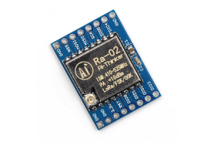
The ESP12E WiFi module is a compact, low-power device specially designed for connecting mobile devices and supporting IoT applications. This module includes an ESP8266 SoC and all the necessary components, like an antenna, to create a reliable wireless network.
With its small size and built-in Wi-Fi capabilities, the ESP12E module makes it easy for a processor or microcontroller to connect to a network. At its core, the ESP8266EX chip provides a high-performance wireless system on a chip (SoC) that supports a variety of use cases.
This module is widely appreciated for its affordability, especially for developing IoT projects. Whether you’re building a smart device or experimenting with wireless connectivity, the ESP12E is an excellent option for those seeking simplicity and functionality.
ESP12E WiFi Module Pinout Details
The ESP12E WiFi module comes with a 24-pin configuration, each serving a unique purpose to ensure smooth operation and versatility. Below is a breakdown of the pins and their respective functionalities.

• Pin1 (RST): This is the reset pin of the Wi-Fi module.
• Pin2 (ADC): It is an analog input pin for the 10-bit ADC.
• Pin3 (EN): This is an active high enable pin for the module.
• Pin4 (GPIO16): General-purpose input/output pin 16.
• Pin5 (GPIO14): General-purpose input/output pin 14.
• Pin6 (GPIO12): General-purpose input/output pin 12.
• Pin7 (GPIO13): General-purpose input/output pin 13.
• Pin8 (VDD): +3.3V input power pin.
• Pin9 (CS0): Chip selection pin for the SPI interface.
• Pin10 (MISO): Master In Slave Out (MISO) pin for the SPI interface.
• Pin11 (GPIO9): General-purpose input/output pin 9.
• Pin12 (GPIO10): General-purpose input/output pin 10.
• Pin13 (MOSI): Master Out Slave In (MOSI) pin of the SPI interface.
• Pin14 (SCLK): Clock pin for the SPI interface.
• Pin15 (GND): Ground pin for the module.
• Pin16 (GPIO15): General-purpose input/output pin 15.
• Pin17 (GPIO2): General-purpose input/output pin 2.
• Pin18 (GPIO0): General-purpose input/output pin 0.
• Pin19 (GPIO4): General-purpose input/output pin 4.
• Pin20 (GPIO5): General-purpose input/output pin 5.
• Pin21 (RXD0): Receiver (RXD) pin of UART0.
• Pin22 (TXD0): Transmitter (TXD) pin of UART0.
Comprehensive Specifications of ESP12E WiFi Module
| Parameter | Specification |
| Wireless Standard | IEEE 802.11 b/g/n protocol |
| Frequency Range | 2.412 to 2.484 GHz |
| Interfaces | UART, SPI, SDIO 2.0 |
| PWM | Available |
| ADC Channels | 1 |
| Operating Temperature Range | -40ºC to +125ºC |
| GPIO | Programmable |
| Standby Power Consumption | Below 1.0 mW |
| Antenna | PCB Antenna |
| Wireless Network Type | AP/STA/STA + AP |
| Integrated MCU | Low-power 32-bit |
| Security Type | WPA-PSK / WEP / WPA2-PSK |
| Leakage Current | < 10 µA |
| Encryption Type | WEP128/WEP64/AES/TKIP |
| Maximum Current Draw (per pin) | 15 mA |
| Network Protocol | IPv4, UDP / TCP / HTTP / FTP |
| Operating Voltage | 3.3V |
Setting Up ESP12E WiFi Module with Arduino Uno
The ESP12E WiFi module is part of the popular 'ESP-XX' series, which includes modules like ESP-01 to ESP-15. While all these modules are built on the ESP8266 SoC, they differ in features such as flash memory, antenna types, and the number of available pins. This flexibility makes the ESP12E a preferred choice for many engineers when it comes to enabling wireless communication between devices. With its onboard microcontroller and compact size, this module offers both functionality and simplicity in one package.
To use the ESP12E with an Arduino Uno, you’ll need a few basic components: an Arduino Uno board, the ESP12E WiFi module, and some connecting wires. The setup process is straightforward, as described below:

• Connect the GND pin of the Arduino Uno to the GND pin of the ESP12E module.
• Link the 3v3 pin of the Arduino Uno to the VCC pin of the ESP12E.
• Attach the TX pin of the Arduino Uno to the TXD0 pin of the ESP12E module.
• Finally, connect the RX pin of the Arduino Uno to the RXD0 pin of the ESP12E.
Once these connections are made, the module can act as a WiFi access point. You can assign it a name and password, allowing other WiFi-enabled devices to connect directly to it. Below is an example of Arduino code to configure the ESP12E module as an access point:
#include
void setup() {
Serial.begin(115200);
WiFi.softAP(“SSID-NAME-HERE”, “WIFI-PASS(8 MAX)”);
}
void loop() {
Serial.printf(“Stations connected = %d\n”, WiFi.softAPgetStationNum());
delay(3000);
}
In this code, the WiFi.softAP function is used to set the WiFi name and password. Once the setup is complete, the loop function tracks the number of connected devices using WiFi.softAPgetStationNum().
Alternatively, if you prefer not to write custom code, you can use AT commands. For example, to set the module as an access point, you can send the command AT+CWMODE=2. You can also change the WiFi name and password with the command AT+CWJAP="SSID","PASSWORD". Make sure to replace the placeholders with your chosen network name and an 8-character password.
This setup process can also be adapted for other microcontrollers. The simplicity and versatility of the ESP12E make it a practical choice for a wide range of wireless communication applications.
How to Interface ESP12E WiFi Module with Pic Microcontroller
The ESP12E WiFi module can work seamlessly with a PIC microcontroller to enable wireless communication. This setup is straightforward when using UART communication, which allows the microcontroller to send commands and receive responses from the module. The interaction is smooth and effective when the setup is configured correctly.
To begin, the UART pins on your PIC microcontroller need to be assigned to match the module’s communication requirements. The example code helps you understand how to initialize the UART settings, send commands, and process the module's responses.
In the provided example, the UART_Init() function ensures that the microcontroller is ready to send and receive data. The UART_Write() function takes care of sending data one character at a time, while the UART_Read() function handles receiving responses from the ESP12E module.
The main interaction happens through the ESP_SendCommand() and ESP_ReceiveResponse() functions. These functions make it easier to send AT commands to the module and process the results. For instance, the ESP_SendCommand("AT\r\n") in the code sends a test command to check if the module is responsive.
This setup allows you to control the module without needing to write extensive code. By using UART communication, you can send a variety of AT commands to manage tasks like connecting to a network or configuring the module’s settings.
Below is the code for interfacing the ESP12E module with a PIC microcontroller:
#include
#include
// Define UART Pins
#define UART_TX RC0
#define UART_RX RC1
// Define UART Baud Rate
#define BAUD_RATE 9600
void UART_Init() {
// Configure UART pins as outputs
TRISCbits.TRISC0 = 0; // TX Pin as output
TRISCbits.TRISC1 = 1; // RX Pin as input
// Configure UART for desired baud rate
uint16_t baud = (_XTAL_FREQ / (16 * BAUD_RATE)) - 1;
SPBRG = baud;
// Enable Asynchronous Serial Port
TXSTAbits.TXEN = 1; // Enable TX
TXSTAbits.SYNC = 0; // Asynchronous mode
RCSTAbits.SPEN = 1; // Enable Serial Port
}
void UART_Write(char data) {
while (!TXIF); // Wait for TX buffer to be empty
TXREG = data; // Write data to TX buffer
}
char UART_Read() {
while (!RCIF); // Wait for data to be received
return RCREG; // Return received data
}
// ESP12E WiFi Module Code
void ESP_Init() {
UART_Init();
}
void ESP_SendCommand(const char* command) {
// Send command to ESP module
for (int i = 0; command[i] != '\0'; i++) {
UART_Write(command[i]);
}
}
char ESP_ReceiveResponse() {
// Receive response from ESP module
return UART_Read();
}
void main() {
// Initialize ESP module
ESP_Init();
// Send AT command and receive response
ESP_SendCommand("AT\r\n");
char response = ESP_ReceiveResponse();
// Process response
while (1) {
// Main program loop
// ...
}
}
List of AT Commands for ESP12E WiFi Module
The ESP12E WiFi module supports a range of AT commands, making it easy to configure and control its functionality. These commands allow you to manage WiFi settings, establish connections, and exchange data effectively. Below is a list of commonly used AT commands for the ESP12E module:
• AT: Test command to check if the module is responsive.
• AT+RST: Reset the module.
• AT+CWMODE: Set the WiFi mode (Station, Access Point, or both).
• AT+CWJAP: Connect to a WiFi network by providing the SSID and password.
• AT+CWLAP: Display a list of available WiFi networks.
• AT+CWQAP: Disconnect from the current WiFi network.
• AT+CIFSR: Retrieve the local IP address.
• AT+CIPSTART: Initiate a TCP or UDP connection.
• AT+CIPSEND: Send data over an active TCP or UDP connection.
• AT+CIPCLOSE: Close an existing TCP or UDP connection.
• AT+CIPMUX: Set the connection mode to single or multiple connections.
• AT+CIPSERVER: Configure the module to operate as a TCP server.
• AT+CIPSTO: Set the timeout for a TCP server connection.
• AT+PING: Ping a remote IP address to check connectivity.
• AT+GMR: Retrieve firmware version information.
These commands cover basic and advanced functions, providing flexibility to interact with the module for various IoT and wireless communication tasks. For a more detailed list of commands, refer to the official datasheet or user manual for the ESP12E module.
Advantages of ESP12E WiFi Module
Affordable Pricing
One of the main advantages of the ESP12E WiFi module is its affordability. You don’t need to spend a lot to add reliable WiFi functionality to your projects, making it a cost-effective solution for both small and large-scale applications.
Low Power Consumption
The module is designed to consume very little power, which is ideal for battery-operated devices or projects where energy efficiency is a priority. This feature allows your projects to run longer without frequent recharges or replacements.
Compact and Portable Design
The ESP12E is small in size, making it easy to integrate into projects with limited space. Its lightweight and portable nature also mean you can use it in applications where size and weight are a concern, such as wearable devices or compact systems.
Standalone Functionality
With its built-in microcontroller, the ESP12E can work as a standalone device without requiring an external microcontroller. This simplifies your setup and reduces the need for additional hardware, making your project more streamlined.
Space-Saving Design
The module’s compact design ensures that it takes up minimal space on your project’s board. This feature is especially beneficial when working with devices that have tight space constraints, such as embedded systems or portable gadgets.
Increased GPIO Pins and Enhanced PCB Features
The ESP12E includes more GPIO (General Purpose Input/Output) pins than many other modules, providing you with greater flexibility to connect and control external components. Additionally, its castellated edges over the PCB (Printed Circuit Board) make soldering easier and allow for better integration into various designs.
Applications and Use Cases of ESP12E WiFi Module
Weather Monitoring Systems
The ESP12E is often used in weather stations to gather and transmit data like temperature, humidity, and atmospheric pressure. Its wireless capabilities make it easy to send this data to servers or cloud platforms for analysis and visualization.
Smart Home Appliances
You’ll find the ESP12E embedded in home appliances like smart refrigerators, air conditioners, and washing machines. It allows these devices to connect to WiFi networks, enabling remote control and monitoring through mobile apps or voice assistants.
IoT-Based Projects
The module is a go-to choice for IoT applications because of its compact size and reliable wireless connectivity. From smart lighting systems to connected sensors, the ESP12E helps bring devices online and interact with each other seamlessly.
Gaming and Toys
In gaming devices and smart toys, the ESP12E allows for wireless interaction, such as controlling the toy remotely or enabling multiplayer gaming over WiFi. This enhances the user experience by adding modern connectivity features to traditional toys and games.
Wireless Control Systems
The module is widely used in systems where wireless control is needed, such as motor controllers, industrial equipment, and drones. Its reliable communication ensures smooth operation and quick response times in these applications.
Security and Home Automation
For home automation, the ESP12E can control devices like door locks, cameras, and alarm systems. Its ability to connect to WiFi networks makes it perfect for sending alerts and allowing users to monitor their home security systems remotely.
Computing Devices
The ESP12E is also used in computers and laptops, especially in projects where additional WiFi functionality is needed. Its low-cost nature makes it a preferred choice for enhancing connectivity in existing systems.
Industrial and Commercial Use
In industries, the ESP12E is implemented in systems like baby monitors, industrial equipment, and wireless location sensing devices. It ensures reliable communication and remote monitoring in these environments.
Wearable Electronics
For wearable devices like fitness trackers or health monitoring gadgets, the ESP12E adds WiFi connectivity without compromising on size or power efficiency. Its compact design is ideal for these space-constrained devices.
Networking Solutions
The ESP12E plays a key role in networking applications, such as wireless access points and mesh networks. It allows devices to connect and communicate effectively within these networks.
About us
ALLELCO LIMITED
Read more
Quick inquiry
Please send an inquiry, we will respond immediately.
The BAV99 Diode and Its Role in Protecting Electronic Devices
on December 17th
SX1278 Lora RF Module: Applications, Interfacing, and Pinout
on December 17th
Popular Posts
-

Complex Instruction Set Computers: How They Changed Computing?
on April 17th 147710
-

USB-C Pinout and Features
on April 17th 111655
-

Using Xilinx Unified Simulation Primitives: A Comprehensive Guide to FPGA Design and Simulation
on April 17th 111314
-

Power Supply Voltages in Electronics: Meaning of VCC, VDD, VEE, VSS, and GND
on April 17th 83579
-

RJ45 Connector Guide: Pinout, Wiring, Cable Types, and Uses
on January 1th 79218
-

The Ultimate Guide to Wire Color Codes in Modern Electrical Systems
The way our electrical systems use colors isn’t just for looks. Each wire color now indicates a specific function, making it easier to identify and handle electrical components correctly during ins...on January 1th 66746
-

Quality (Q) Factor: Equations and Applications
The quality factor, or 'Q', is important when checking how well inductors and resonators work in electronic systems that use radio frequencies (RF). 'Q' measures how well a circuit minimizes energy...on January 1th 62925
-

Purge Valve Guide: Function, Symptoms, Testing, and Replacement for Optimal Engine Performance
The purge valve is a key part of a car’s system that helps keep the air clean by managing fuel vapors before they can escape into the atmosphere. This not only helps the environment by reducing pol...on January 1th 62793
-

Achieving Peak Performance with the Maximum Power Transfer Theorem
The Maximum Power Transfer Theorem explains how energy from a source, such as a battery or generator, flows to a connected load. It shows the exact condition where the load receives the most power....on January 1th 54020
-

A23 Battery Specifications and Compatibility
The A23 battery is a small, cylinder-shaped battery with high voltage. Also called 23A, 23AE, or MN21, it runs at 12 volts and much higher than AA or AAA batteries. Its special design make...on January 1th 51936
HOT Part Number
-
MAX3956ETJ+
Analog Devices Inc./Maxim Integrated
IC TRANSCEIVER FULL 1/1 32TQFN
NFM41CC471R2A3L
Murata Electronics
CAP FEEDTHRU 470PF 100V 1806
MAX8566ETJ+T
Analog Devices Inc./Maxim Integrated
IC REG BUCK ADJ 10A 32TQFN
FTSH-104-01-L-DV-P-TR
Samtec Inc.
CONN HEADER SMD 8POS 1.27MM
ADXL325BCPZ-RL7
Analog Devices Inc.
ACCELEROMETER 5G ANALOG 16LFCSP
MINISMDC075F/33-2
Littelfuse Inc.
PTC RESET FUSE 33V 750MA 1812
ADUM140D1BRWZ
Analog Devices Inc.
DGTL ISO 3750VRMS 4CH GP 16SOIC
DK1A1B-12V
Panasonic Electric Works
RELAY GEN PURPOSE DPST 8A 12V
NL27WZ126USG
onsemi
IC BUFFER NON-INVERT 5.5V US8
08055F103K4Z2A
KYOCERA AVX
CAP CER 10000PF 50V X8R 0805
AD9057BRSZ-80
Analog Devices Inc.
IC ADC 8BIT PIPELINED 20SSOP
OPA4131PA
Burr Brown
IC OPAMP JFET 4 CIRCUIT 14DIP
ACTP112
Panasonic Electric Works
RELAY AUTOMOTIVE SPDT 30A 12V
TLC339CN
Texas Instruments
IC COMPARATOR 4 GEN PUR 14DIP
ZX62M-B-5P
Hirose Electric Co Ltd
CONN RCPT USB2.0 MICRO B SMD
AD8428ARZ
Analog Devices Inc.
IC INST AMP 1 CIRCUIT 8SOIC
SP706TEU-L
MaxLinear, Inc.
IC SUPERVISOR 1 CHANNEL 8MSOP
BZX84C20
Good-Ark Semiconductor
DIODE, ZENER, 0.3W, 20V, SOT-23 -
2N681
Solid State Inc.
TO 48 25 AMP SCR
UCC3818DWTR
Texas Instruments
IC PFC CTR AVERAGE 220KHZ 16SOIC
MMBF5460LT1
onsemi
JFET P-CH 40V 0.225W SOT23
FSA3341UMX
onsemi
IC INTERFACE SPECIALIZED 16UMLP
1808HA270JAT1A
KYOCERA AVX
CAP CER 27PF 3KV NP0 1808
CY7C64215-28PVXCT
Infineon Technologies
IC CNTRLR USB FS 28SSOP
BLM15EG121SN1D
Murata Electronics
FERRITE BEAD 120 OHM 0402 1LN
HI3-0201HS-5
Harris Corporation
IC SWITCH SPST-NCX4 50OHM 16DIP
FAN53528DUC40X
onsemi
IC REG BUCK PROG 3A 15WLCSP
PI6C2405A-1HLE
Diodes Incorporated
IC ZD BUFFER 8TSSOP
2SK2624LS
onsemi
N-CHANNEL SILICON MOSFET
MAX4196ESA+T
Analog Devices Inc./Maxim Integrated
IC INST AMP 1 CIRCUIT 8SOIC
WSL25125L000FTB
Vishay Dale
RES 0.005 OHM 1% 1W 2512
HMC474SC70ETR
Analog Devices Inc.
IC RF AMP WIMAX 0HZ-6GHZ SC70-6
STPS20L15D
STMicroelectronics
DIODE SCHOTTKY 15V 20A TO220AC
GRM033R61A272KA01D
Murata Electronics
CAP CER 2700PF 10V X5R 0201
TSOP4836ZC1
Vishay Semiconductor Opto Division
IC SENSOR REMOTE OPTICAL
HA4890
Sensata-Crydom
SSR RELAY SPST-NO 90A 48-530V -

M24C16-FMH6TG
STMicroelectronics
IC EEPROM 16KBIT I2C 5UFDFPN
IRFP21N60L
Vishay Siliconix
MOSFET N-CH 600V 21A TO247-3
RVQ040N05TR
Rohm Semiconductor
MOSFET N-CH 45V 4A TSMT6
AD7416AR
Analog Devices Inc.
SENSOR DIGITAL -40C-125C 8SOIC
PCM2906DB
Texas Instruments
IC STEREO AUD CODEC W/USB 28SSOP
S-8551AA-M5T1U
ABLIC Inc.
IC REG BUCK ADJ 600MA SOT23-5
LTC3835IUFD#PBF
Analog Devices Inc.
IC REG CTRLR BUCK 20QFN
GCM31ML81H104KA37L
Murata Electronics
CAP CER 0.1UF 50V X8L 1206
TPA3120D2PWPR
Texas Instruments
IC AMP CLASS D STER 25W 24HTSSOP
GBL206
Yangzhou Yangjie Electronic Technology Co.,Ltd
RECT BRIDGE 600V 2A 2KBJ
NCV7321D11R2G
onsemi
IC TRANSCEIVER HALF 1/1 8SOIC
06035A8R2C4T2A
KYOCERA AVX
CAP CER 8.2PF 50V NP0 0603
VI-PU13-EVW
Vicor Corporation
VI-PU13-EVW 12V 24V 150W 100W
XC6VLX240T-1FFG1759I
AMD
IC FPGA 720 I/O 1759FCBGA
VNI4140K-32
STMicroelectronics
IC PWR DRVR N-CHAN 1:1 PWRSSO24
TS271IN
STMicroelectronics
IC OPAMP GP 1 CIRCUIT 8DIP
AT49LV1024A-45VC
Microchip Technology
IC FLASH 1MBIT PARALLEL 40VSOP
AD7864BSZ-1
Analog Devices Inc.
IC ADC 12BIT SAR 44MQFP