Basic Transistor Amplifier Circuit Explained
If you've ever wanted to build your own amplifier using simple parts, a common emitter transistor circuit is a great place to start. It's easy to understand, works well with both logic and audio signals, and doesn't require any complicated tools or advanced math. You'll learn how to make small signals stronger, how to choose the right components, and how to test your circuit once it's built. This guide walks you through the steps in a clear, friendly way so you can follow along without getting lost. You'll also see how to improve the basic design to make your amplifier more stable and powerful. Whether you're just starting out or trying to improve your skills, this is a solid introduction to a practical and flexible circuit. With a little practice, you'll be building and customizing your own amplifiers in no time.Catalog

Figure 1. Emitter Transistor Circuit
Emitter Transistor Circuit
The common emitter amplifier is one of the most popular transistor circuits you'll come across. It's used in many electronic devices because it offers good gain and is fairly simple to put together. The good news is—you don't need to be an expert to design one. With just a few clear steps and a bit of understanding, you can design a reliable and effective circuit that works well for many applications.
What makes this amplifier design approachable is how straightforward the math is. You won't be overwhelmed by complex formulas. A few simple calculations using Ohm's Law and basic transistor properties can guide you to the right resistor and capacitor values. Once you get the hang of the process, picking parts becomes a lot easier, especially since you can often choose standard resistor values without throwing the circuit off.
There's also a lot of flexibility with this type of amplifier. You can start with a very simple version—a basic logic buffer or output driver—using just a transistor, a resistor at the input, and one at the collector. Even in this basic form, the circuit can be useful, especially when you need to convert a signal from high to low or vice versa. This is because the circuit inverts the signal: when the input goes high, the output drops low.
If you want to take things a step further, you can add a few extra parts. These include capacitors to handle AC signals and resistors to help set the correct operating point for the transistor. An emitter bypass capacitor can also be added to improve the gain for AC signals. These additions don’t make the circuit much more complicated, but they do give you better control over how the amplifier performs. With just a bit of practice and tweaking, you'll be able to design a version that works well for your specific needs.
Simple Common Emitter Circuit for Logic Signals
This type of common emitter circuit is probably one of the easiest transistor circuits you can build. It’s often used as a simple logic buffer or signal inverter, and it's a great starting point if you're just getting into transistor-based electronics. The setup is minimal—you only need a transistor, one resistor connected to the input (the base of the transistor), and another resistor connected at the collector. Even with just these few parts, the circuit does something quite useful.
The input resistor helps by controlling the amount of current that flows into the base of the transistor. This prevents too much current from damaging the transistor or affecting other parts of your circuit. Meanwhile, the collector resistor plays a different role. It's where the output voltage is developed. When the transistor turns on, current flows through it, and the collector voltage drops, creating a low signal at the output.
The way the circuit works is simple but clever. When the input signal is high—let’s say from a logic gate or microcontroller—it pushes a small current into the base of the transistor. This small base current allows a larger current to flow from the collector to the emitter, turning the transistor "on." When that happens, the voltage at the collector drops close to zero, and you get a low output. In other words, a high input gives you a low output, which is called inversion or phase reversal. This is a key feature of the common emitter amplifier.
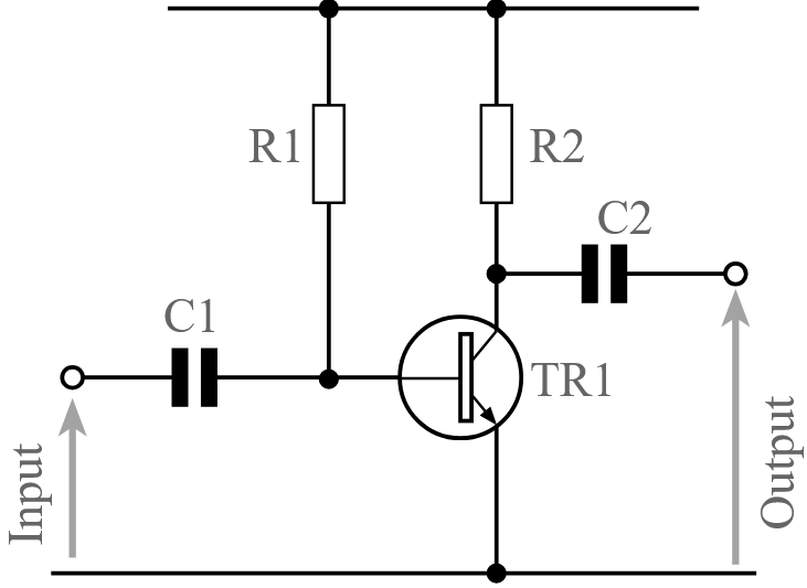
Figure 2. Basic Common Emitter Transistor Amplifier for Logic Use
This kind of circuit is very handy when you want to drive a low signal device or need to shift levels between different parts of a digital system. For example, it can be used to control an LED or act as a simple interface between logic ICs. It's quick to build, easy to understand, and doesn’t take up much space or power. So if you’re designing a logic-level circuit and need a reliable switching stage, this common emitter setup is a smart and simple option.
Step-by-Step Guide for Basic Logic Amplifier Design
Building a common emitter logic amplifier is easy once you break it down into simple steps. This part of the guide helps you choose the right parts and figure out their values so your circuit works the way it should. Each step focuses on one part of the setup, making it easy to follow along.
• Pick the Right Transistor
Start by picking a transistor that suits your project. Think about how much current your circuit will use and how fast the transistor needs to turn on and off. For logic circuits, fast switching is important, so a switching transistor is usually the best choice. Make sure it can handle the voltage between the collector and emitter. Also, check its current gain (shown as β or hFE). This tells you how much base current is needed to control the transistor. A higher gain means you'll need less base current, but it's always safer to plan for a lower gain just in case.
• Find the Collector Resistor
The collector resistor sets the output voltage when the transistor is on or off. To figure out its value, you first need to know how much current your load needs. Then, using Ohm's Law (R = V / I), you can calculate the resistor value. For example, if you have a 5V power supply and want 5mA of current, you’ll need a 1kΩ resistor (5V ÷ 0.005A). It's fine to round it to the nearest standard resistor value.
• Find the Base Resistor
To fully switch the transistor on, it needs enough current at the base. Divide the collector current by the gain (β) to find the base current. Then, use the voltage difference between your input and the base-emitter voltage (usually about 0.6V for silicon transistors) to find the resistor value. For instance, if your input is 5V and you want 0.25mA at the base, the resistor should be (5V - 0.6V) ÷ 0.00025A = 17.6kΩ. You can round that to a nearby standard value like 18kΩ.
• Double-Check Everything
Before finishing up, go back and check all your numbers. Make sure the transistor can handle the current and voltage. Check that the output voltage drops low enough when it's on, and that your input source can provide the needed base current. Also, confirm your resistors are standard values and can handle the power without heating up too much. If anything seems off, adjust it and recalculate. A quick check now can save a lot of time later.
Simple AC-Coupled Common Emitter Amplifier
This version of the common emitter amplifier includes a coupling capacitor, which makes it more suitable for working with AC signals like audio or other changing voltage inputs. The capacitor is placed at the input to block any DC voltage that might be coming from the previous stage, allowing only the AC part of the signal to pass through. This setup helps when you want to amplify signals that vary over time, without affecting the DC biasing of the transistor.
However, this design uses only a single resistor to bias the base of the transistor. While that keeps things simple, it also means the transistor's operating point, or DC bias, isn’t very stable. That's because the biasing depends heavily on the transistor's current gain (β), which can vary a lot from one transistor to another—even within the same type. As a result, the amplifier might not always work the same way if the transistor is replaced or if the temperature changes, since both can affect β.
Still, this circuit can be useful when you don’t need perfect stability and just want a quick, simple AC amplifier. It’s a good starting point for learning how AC coupling works and how transistors behave in an amplifier. Once you understand the basics here, you’ll be better prepared to build more stable and flexible versions by adding more resistors and other components later.

Figure 3. AC-Coupled Common Emitter Amplifier with One Base Resistor
Steps to Build a Basic AC-Coupled Amplifier
Putting together a basic AC-coupled amplifier is a simple process when you follow a few clear steps. This kind of amplifier is often used for signals that change over time, like audio. The following steps help you pick the right parts and check that everything works as expected.
• Choose the Transistor
Start by choosing a transistor that matches your circuit's needs. Think about how much voltage it will handle between the collector and emitter, how much power it might need to handle, and what frequency range it should work in. For general-purpose amplifiers, a basic NPN transistor like the 2N3904 often works well, but you can choose others based on your specific project.
• Choose the Collector Resistor
The collector resistor helps set the output voltage. A good starting point is to set the collector at about half the supply voltage. This gives your signal room to swing both up and down. Use Ohm's Law (R = V / I) to find the value. Just decide how much current you want flowing through the resistor, and divide the voltage across it by that current.
• Choose the Base Resistor
To get the transistor working correctly, you need to feed the right amount of current into its base. First, divide the collector current by the transistor's gain (β) to find the base current. Then, use the supply voltage and the fact that the base will usually sit about 0.6V above ground to find the base resistor. Ohm's Law comes in handy here again.
• Calculate the Coupling Capacitors
Capacitors are used to block DC and pass AC signals. To pick the right size, look at the lowest frequency your signal will use and the input or output resistance it will go through. Use the formula Xc = 1 / (2πfC) to make sure the capacitor's reactance matches the impedance at that frequency. This keeps your signal strong without cutting off the low end.
• Revisit Your Calculations
Once you've picked all the parts, take a moment to double-check everything. Look over your resistor values, current levels, and capacitor choices. Make sure the transistor is operating in the right range and the signal path is clear. Small tweaks at this stage can make your amplifier perform much better once it's built.
Better AC-Coupled Common Emitter Amplifier
When you want a more reliable and better-performing amplifier, this version of the common emitter circuit is the way to go. By adding a few extra components—like more resistors and capacitors—you make the circuit more stable and improve its gain, especially for AC signals. These added parts help the amplifier stay consistent, even if the transistor’s properties change slightly or the temperature shifts.
One of the key improvements in this design is the use of a voltage divider made with two resistors to bias the base. This makes the base voltage much more predictable, which means the transistor stays in its correct operating region more reliably. The circuit also includes an emitter resistor that sets the emitter voltage and helps with stability. This resistor makes the transistor less sensitive to changes in current gain (β), which is important if you're aiming for consistent performance.
To boost the AC gain, a capacitor is added across the emitter resistor. This bypass capacitor allows AC signals to "skip" the resistor, increasing the overall gain of the circuit for those signals while still keeping the DC biasing stable. The result is a circuit that’s not only more dependable but also gives you a stronger, cleaner output signal.
This version is especially useful when you're building something more permanent or when your amplifier needs to connect to other stages without losing signal quality. It might look a bit more complex than the basic version, but the benefits it brings in performance and reliability make it a great step forward once you’re comfortable with the simpler designs.

Figure 4. Improved Common Emitter Amplifier with More Components
Steps to Build a Basic AC-Coupled Amplifier
This version of the amplifier includes more components, which gives you better performance, especially when it comes to gain and DC stability. The following steps break down the process of choosing values and designing your circuit clearly and simply.
• Choose the Transistor
Pick a transistor based on what your circuit needs in terms of voltage, current, and signal type. A general-purpose NPN transistor works well for many cases, but make sure it can handle your supply voltage and current without any trouble.
• Calculate the Collector Resistor
Decide how much current your circuit needs to feed into the next stage. Then choose a collector voltage that’s about half of the supply voltage—this gives your signal room to move up and down. Use Ohm's Law (R = V / I) to figure out the right resistor value.
• Calculate the Emitter Resistor
For better stability, set the emitter voltage at around 1V or about 10% of your supply voltage. Since emitter current is nearly the same as collector current, you can calculate the emitter resistor by dividing the emitter voltage by the current.
• Determine the Base Current
To find the base current, divide the collector current by the transistor's gain (β or hFE). If the gain varies, it's safer to use the lower end of the range to make sure the transistor still turns on properly.
• Determine the Base Voltage
The base voltage is the emitter voltage plus the base-emitter junction voltage. For silicon transistors, this is about 0.6V. So, if the emitter is at 1V, the base should be at around 1.6V.
• Set Base Resistor Values
Use two resistors in a voltage divider (R1 and R2) to get the correct voltage at the base. A good rule is to make the current flowing through them about ten times the base current. This helps keep the base voltage stable. Choose the resistor values based on the voltage needed and your supply voltage.
• Add the Emitter Bypass Capacitor
To improve AC gain, add a capacitor across the emitter resistor. This allows AC signals to bypass the resistor, increasing gain. Choose a capacitor with a reactance equal to the emitter resistor at your circuit's lowest frequency.
• Choose the Input Capacitor
The input capacitor should have a reactance that matches the input resistance at the lowest frequency of your signal. This keeps low-frequency signals from being blocked. You can estimate the input resistance as the transistor's gain times the emitter resistor value.
• Choose the Output Capacitor
This capacitor passes the amplified signal to the next stage while blocking DC. Choose a value that matches the resistance of the load (the next part of the circuit) at the lowest frequency you're working with.
• Re-evaluate Your Assumptions
Once your design is complete, take a moment to go back and check everything. Make sure the transistor can still handle the current and voltage, your resistor values make sense, and all your capacitor choices support the right frequencies. A quick review helps avoid problems later.
Understanding Frequency Response and Signal Bandwidth
When you build a common emitter amplifier, it helps to know how it handles different signal frequencies. Some signals pass through easily, while others might get weaker depending on the parts you use—especially the capacitors and resistors.
The range of frequencies your amplifier can handle well is called its bandwidth. At very low frequencies, the capacitors can act like blocks because their resistance (called reactance) goes up. At high frequencies, they allow signals to pass more easily. That's why it's important to choose capacitor values based on the lowest frequency your circuit needs to work with. For example, if your signal goes down to 20 Hz, your capacitors should be large enough to let that through without too much loss.
The capacitor across the emitter resistor—known as the bypass capacitor—also makes a big difference. It helps increase the amplifier's gain for AC signals. If this capacitor is too small, your circuit may lose gain at lower frequencies. But with the right value, it boosts performance without affecting your DC setup.
Understanding this helps you pick parts that make your amplifier work better for the signals you're using, whether it's for audio, sensors, or other AC sources. Once you get the hang of it, adjusting your design for different frequency ranges becomes much easier.
How to Measure and Test Your Amplifier Circuit
After putting your amplifier circuit together, it's a good idea to check that everything is working as expected. You don’t need complicated tools—a simple multimeter is often enough to get started, and an oscilloscope is helpful if you want to look at the signal in more detail.
Begin by using the multimeter to check the supply voltage and confirm it's reaching the circuit. Then measure the voltage at the collector, base, and emitter of the transistor. In most cases, the collector should be somewhere around half the supply voltage, while the emitter will be a bit above ground. The base should be about 0.6 volts higher than the emitter if you're using a silicon transistor. These readings help you know if the transistor is biased properly and ready to amplify.
If you have a signal generator and an oscilloscope, you can test how the amplifier handles a small AC signal. Connect a low-frequency sine wave to the input and check the output on the scope. You should see a bigger version of the input signal, flipped upside down. If the output looks too weak or distorted, double-check your resistor or capacitor values.
Even without a scope, you can try using an audio signal—like from a phone or music player—and connect a small speaker to the output through a capacitor. If you hear the sound, it means the amplifier is working.
Testing helps make sure your circuit is doing what it’s supposed to, and it also gives you a better feel for how it behaves. It’s a simple but useful step that makes your project more reliable.
More Help with Choosing Transistors
As you spend more time working with transistor circuits, especially common emitter amplifiers, picking the right transistor becomes easier and more natural. At first, it might feel like there are too many options, but over time, you'll get a better sense of what works best for different types of circuits. You'll start to recognize patterns—like which transistors are good for general-purpose amplifiers and which ones are more suited for switching.
For amplifier circuits, you'll usually want a transistor that offers a decent gain, handles your supply voltage comfortably, and performs well at the frequency you're working with. You don't always need something high-end—many common, affordable transistors work perfectly well for basic audio or signal amplifiers.
On the other hand, if you're building a circuit where the transistor acts more like an on-off switch—such as controlling an LED, motor, or relay—it’s better to choose a switching transistor. These are designed to turn on and off quickly and handle sharp changes in current without lag. Even if a transistor has a high speed rating or a fast response time (like a high ft), it doesn’t always mean it will perform well in a switching circuit. Switching transistors are made to handle fast transitions and sudden loads more effectively.
So as a general rule, try to match the transistor to the job it needs to do. With practice, you'll find a few go-to options that work in most of your circuits. Whether it's for amplifying a signal or acting as a digital switch, using the right type of transistor will help your circuits run more reliably and perform just the way you expect.
Conclusion
Now that you've explored how a common emitter amplifier works and how to build one step by step, you should feel more confident putting your own circuit together. Whether you're working with simple logic signals or amplifying AC inputs like audio, this type of circuit is a solid choice. Just remember to take your time with the calculations and double-check your component values. With a bit of practice, you'll find it easier to create amplifiers that work well for whatever project you're working on.
About us
ALLELCO LIMITED
Read more
Quick inquiry
Please send an inquiry, we will respond immediately.
Frequently Asked Questions [FAQ]
1. What does a common emitter amplifier do?
A common emitter amplifier takes a small input signal and makes it bigger. It’s often used to boost audio or other signals so they can drive another stage or device.
2. Why is the output inverted in a common emitter circuit?
The output is inverted because of how the transistor works in this setup. When the input goes high, the transistor turns on and pulls the output low, creating the opposite signal.
3. Do I need a bypass capacitor in my amplifier?
You don’t have to use one, but adding a bypass capacitor across the emitter resistor helps increase the AC gain. It lets AC signals pass while still keeping the DC stability.
4. How do I know what resistor values to use?
Use Ohm’s Law to calculate the resistor values based on your supply voltage and desired current. Standard resistor values close to your result usually work fine.
5. Can I use any NPN transistor for this circuit?
You can use most general-purpose NPN transistors, but it’s better to choose one that matches your voltage, current, and speed needs. For logic switching, use a transistor made for switching.
Complete Guide to the 0402 Resistor: Specifications, Applications, and Soldering Techniques
on April 1th
How the LCMXO1200C-3BN256C Works and Where to Use It
on March 31th
Popular Posts
-

Complex Instruction Set Computers: How They Changed Computing?
on April 18th 147749
-

USB-C Pinout and Features
on April 18th 111904
-

Using Xilinx Unified Simulation Primitives: A Comprehensive Guide to FPGA Design and Simulation
on April 18th 111349
-

Power Supply Voltages in Electronics: Meaning of VCC, VDD, VEE, VSS, and GND
on April 18th 83714
-

RJ45 Connector Guide: Pinout, Wiring, Cable Types, and Uses
on January 1th 79502
-

The Ultimate Guide to Wire Color Codes in Modern Electrical Systems
The way our electrical systems use colors isn’t just for looks. Each wire color now indicates a specific function, making it easier to identify and handle electrical components correctly during ins...on January 1th 66868
-

Quality (Q) Factor: Equations and Applications
The quality factor, or 'Q', is important when checking how well inductors and resonators work in electronic systems that use radio frequencies (RF). 'Q' measures how well a circuit minimizes energy...on January 1th 63004
-

Purge Valve Guide: Function, Symptoms, Testing, and Replacement for Optimal Engine Performance
The purge valve is a key part of a car’s system that helps keep the air clean by managing fuel vapors before they can escape into the atmosphere. This not only helps the environment by reducing pol...on January 1th 62939
-

Achieving Peak Performance with the Maximum Power Transfer Theorem
The Maximum Power Transfer Theorem explains how energy from a source, such as a battery or generator, flows to a connected load. It shows the exact condition where the load receives the most power....on January 1th 54076
-

A23 Battery Specifications and Compatibility
The A23 battery is a small, cylinder-shaped battery with high voltage. Also called 23A, 23AE, or MN21, it runs at 12 volts and much higher than AA or AAA batteries. Its special design make...on January 1th 52087
HOT Part Number
-

LTC4063EDD#TRPBF
Analog Devices Inc.
IC BATT CHG LI-ION 1CELL 10DFN
MIMX8MM1CVTKZAA
NXP USA Inc.
IC MPU I.MX 8M MINI SOLOLITE
APDS-9005-020
Broadcom Limited
SENSOR OPT 500NM AMB 6CHIPLED
06031A820KAT2A
KYOCERA AVX
CAP CER 82PF 100V C0G/NP0 0603
ICM-20602
TDK InvenSense
IMU ACCEL/GYRO/TEMP I2C/SPI LGA
170M4611
Eaton - Bussmann Electrical Division
FUSE SQUARE 350A 700VAC RECT
08053C105JAZ2A
KYOCERA AVX
CAP CER 1UF 25V X7R 0805
EP1C12F324C6N
Intel
IC FPGA 249 I/O 324FBGA
2SC4617T1G
onsemi
TRANS NPN 50V 0.1A SC75 SOT416
TL431AILPRAG
onsemi
IC VREF SHUNT ADJ 1% TO92-3
ADAU1787BCBZRL
Analog Devices Inc.
4 ADC, 2 DAC LOW POWER CODEC, AU
74VHC164MTCX
onsemi
IC SHIFT REGISTER 8BIT 14TSSOP
DAN222M3T5G
onsemi
DIODE ARRAY GP 80V 100MA SOT723
NR3015T470M
Taiyo Yuden
FIXED IND 47UH 300MA 1.608OHM SM
MM3Z18VC
onsemi
DIODE ZENER 18V 200MW SOD323F
1N4001W
Rectron USA
DIODE GEN 1A 50V SOD-123F
SMBJ90A
Taiwan Semiconductor Corporation
TVS DIODE 90VWM 146VC DO214AA
NTA1215MC
Murata Power Solutions Inc.
DC DC CONVERTER +/-15V 1W -
SDR1307-101KL
Bourns Inc.
FIXED IND 100UH 1.9A 180MOHM SMD
AOT5B65M1
Alpha & Omega Semiconductor Inc.
IGBT 650V 5A TO220
STP16CP596B1R
STMicroelectronics
IC LED DRIVER LINEAR 50MA 24DIP
AD7895ANZ-2
Analog Devices Inc.
IC ADC 12BIT SAR 8DIP
MURB1620CTT4G
onsemi
DIODE ARRAY GP 200V 8A D2PAK
STGIPS30C60T-H
STMicroelectronics
MOD IPM SLLIMM 30A 600V 25SDIP
IXDN604SIA
IXYS Integrated Circuits Division
IC GATE DRVR LOW-SIDE 8SOIC
CY7C63743-SC
Infineon Technologies
IC MCU 8K LS USB/PS-2 24-SOIC
U2745B-MFBG3
Microchip Technology
RF TX IC UHF 310-440MHZ 16LSSOP
DSPIC30F4013T-30I/PT
Microchip Technology
IC MCU 16BIT 48KB FLASH 44TQFP
ADF4106BRUZ-RL
Analog Devices Inc.
IC CLK/FREQ SYNTH 16TSSOP
EL8403IS
Elantec
IC OPAMP GP 4 CIRCUIT 14SOIC
8A35001B-001AJG
Renesas Electronics America Inc
NETWORK TIMING
GRM0337U1HR90BD01D
Murata Electronics
CAP CER 0.9PF 50V U2J 0201
LT1356CS#PBF
Analog Devices Inc.
IC VOLTAGE FEEDBACK 2 CIRC 16SO
AON7280
Alpha & Omega Semiconductor Inc.
MOSFET N-CH 80V 20A/50A 8DFN
IRLI540N
Infineon Technologies
MOSFET N-CH 100V 23A TO220AB FP
VI-J6Z-MZ
Vicor Corporation
VI-J6Z-MZ 300V 2V 5A -
LMH6722MA
Texas Instruments
IC AMP CURRENT FEEDBACK 14SOIC
HZM6.8Z4MWATL-E
Renesas Electronics America Inc
TVS DIODE 3.5VWM 3MPAK
LM4041DIM7-1.2
Texas Instruments
IC VREF SHUNT 1% SC70-5
RT6200GE
Richtek USA Inc.
IC REG BUCK ADJ 600MA SOT23-6
R5F21274SNFP#X6
Renesas Electronics America Inc
IC MCU 16BIT 16KB FLASH 32LQFP
1N5227B
onsemi
DIODE ZENER 3.6V 500MW DO35
12102C472JAT2A
KYOCERA AVX
CAP CER 4700PF 200V X7R 1210
PZTA64
Fairchild Semiconductor
SMALL SIGNAL BIPOLAR TRANSISTOR,
XC1765ELSO8C
AMD
IC PROM SER C-TEMP 3.3V 8-SOIC
XR88C92CJ-F
MaxLinear, Inc.
IC UART FIFO DUAL 44PLCC
RT24C2X202
Bourns, Inc.
TRIMMER 2K OHM 0.75W PC PIN SIDE
DLW31SN900SQ2L
Murata Electronics
CMC 370MA 2LN 90 OHM SMD
LMK432F476ZM-T
Taiyo Yuden
CAP CER 47UF 10V Y5V 1812
MOC207R1VM
onsemi
OPTOISO 2.5KV TRANS W/BASE 8SOIC
GRM0335C1E390JD01D
Murata Electronics
CAP CER 39PF 25V C0G/NP0 0201
SE10PG-M3/84A
Vishay General Semiconductor - Diodes Division
DIODE GEN PURP 400V 1A DO220AA
RABS15M REG
Taiwan Semiconductor Corporation
BRIDGE RECT 1P 1KV 1.5A ABS-L
PI74LPT16245AEX
Diodes Incorporated
IC TXRX NON-INVERT 3.6V 48TSSOP