
Zener Diode Function and Uses in Electronics Circuits
A Zener diode is a unique semiconductor device designed to maintain precise voltage control in various electronic applications. In this guide, you’ll learn how it works in reverse bias and how you can use it for voltage regulation, voltage reference, surge protection, and signal control. You’ll also see how it helps in waveform clipping, switching, and voltage shifting to make your circuits more stable and reliable.Catalog

Figure 1. Zener Diodes
How Zener Diodes Work?
A Zener diode controls voltage by operating in its reverse breakdown region. When the reverse voltage rises to a specific point called the Zener voltage (Vz), the diode starts conducting in the reverse direction. As it conducts, it keeps the voltage across its terminals nearly constant.
This steady behavior allows the diode to stabilize circuits even when the input voltage or load current fluctuates. Because of this, Zener diodes are needed for keeping voltages consistent in both analog and digital systems.
Zener Diode as a Voltage Regulator

Figure 2. Zener Voltage Regulator Circuit
A Zener diode is commonly used as a simple voltage regulator to maintain a stable output voltage despite variations in input or load. In the circuit shown, the Zener diode is connected in reverse bias across the load resistor RL, while a series resistor R limits the current flowing through the diode.
When the input voltage Vin increases, the excess voltage drops across R, keeping the Zener diode voltage VZ nearly constant. The diode then conducts just enough current IZ to hold the output voltage Vout steady. Conversely, if Vin or the load current IL decreases, the Zener current adjusts automatically to maintain regulation.
This self-balancing behavior makes the circuit both simple and reliable, ideal for low-power DC regulation such as 5 V or 12 V supplies.
Zener Diode as a Voltage Reference

Figure 3. Zener Diode as a Voltage Reference Circuit
Zener diodes are often used to provide a highly stable voltage reference for precision circuits. In the circuit shown, the Zener diode D1 maintains a constant 9.1 V reference at the non-inverting input of the operational amplifier OA1. The voltage divider formed by R1 and R2 feeds a scaled portion of the 12 V supply to the op-amp’s inverting input, allowing it to compare this divided voltage against the Zener reference.
When the output voltage changes, the op-amp adjusts the gate of the P-channel MOSFET M1 (IRF9530) to restore balance between the two inputs. This feedback control keeps the output voltage stable and precise, regardless of load or supply variations. Such a configuration is widely used in ADCs, DACs, and other analog systems that require an accurate reference source.
Zener Diode in Surge Protection

Figure 4. Zener Diode in Surge and Transient Protection Applications
Zener diodes play a role in protecting sensitive electronic components from voltage surges and transient spikes. As shown in the figure, they are placed across circuit points to absorb sudden voltage rises caused by switching surges, inductive loads, or electrostatic discharge (ESD).
When the input voltage exceeds the Zener breakdown level, the diode conducts immediately, clamping the excess voltage and preventing it from reaching downstream devices. In switching circuits, it suppresses power-line spikes; in inductive loads, it absorbs back-EMF energy; and in connectors, it guards against ESD events. This fast, repeatable action makes Zener diodes highly effective for ensuring stable and durable circuit operation.
Zener Diode in Waveform Clipping

Figure 5. Zener Diode Waveform Clipping Circuit and Output Waveform
Zener diodes can be used to limit or “clip” signal amplitudes, preventing excessive voltage swings. In the circuit shown, two Zener diodes are connected in opposite directions across the signal line, allowing current to flow only when the input voltage exceeds the breakdown voltage of either diode.
As the input waveform rises or falls beyond the preset Zener voltages, the diodes conduct and clamp the signal, producing a flattened or clipped output. This results in the output waveform being restricted between two voltage limits, as illustrated on the right side of the figure. Such clipping circuits are commonly used in audio systems, communication circuits, and input protection networks to maintain clean, distortion-free signal levels.
Zener Diode in Switching Circuits

Figure 6. Zener Diode Used for Switching Threshold Control
Zener diodes are frequently used in switching circuits to establish precise voltage trigger levels. As shown in the figure, when the input voltage rises and reaches the Zener breakdown level, the diode conducts and produces a stable reference point that defines the switching threshold.
In diagram (A), the diode conducts once the input exceeds its breakdown voltage, creating a fixed voltage drop that determines when a transistor or logic device should activate. In diagram (B), the same principle is applied, where the switching voltage is defined as the supply voltage minus the Zener voltage (6 – ZDV). This predictable voltage threshold ensures reliable operation in voltage detectors, sensor interfaces, and digital trigger circuits even under supply variations.
Zener Diode in Voltage Shifters

Figure 7. Zener Diode Used in Voltage Level Shifting Circuit
Zener diodes can shift voltage levels between circuits operating at different supply voltages. In the circuit shown, the diode is connected in reverse bias with a resistor in series, producing a fixed voltage drop equal to its Zener voltage VZ. When the input voltage Vin increases beyond VZ, the diode conducts and maintains the output voltage Vout at a value equal to Vin−VZ.
The graph beside the circuit shows how the output voltage begins to rise only after the input surpasses the Zener threshold, creating a precise voltage offset. This predictable level shift allows mixed-voltage systems such as microcontrollers, analog interfaces, or logic circuits to communicate safely and reliably without exceeding their voltage limits.
Conclusion
Zener diodes play a role in maintaining voltage stability, providing precise reference levels, and protecting circuits from transient surges. Their ability to operate safely in reverse bias makes them good for voltage regulation, clipping, and level shifting. Whether used in analog, digital, or mixed-signal systems, these diodes enhance performance and ensure circuit reliability. Their versatility and predictable behavior make them important components in both power and signal control applications.
About us
ALLELCO LIMITED
Read more
Quick inquiry
Please send an inquiry, we will respond immediately.
Frequently Asked Questions [FAQ]
1. Are Zener diodes suitable for high-current or power applications?
Standard Zener diodes are best for low-power circuits. For higher power or surge protection, use higher wattage Zener diodes or TVS (Transient Voltage Suppression) diodes.
2. How do I identify the polarity of a Zener diode?
The cathode (marked with a band) is connected to the positive voltage in reverse bias operation. This orientation allows it to regulate or clamp voltage effectively.
3. What’s the difference between a Zener diode and a TVS diode?
A Zener diode is used for steady-state voltage regulation, while a TVS diode is designed to protect circuits from short-duration voltage spikes and surges.
4. Can I use multiple Zener diodes together?
Yes. You can connect Zener diodes in series to increase the total voltage rating or in parallel (with balancing resistors) to handle higher current levels.
5. Why does my Zener diode get hot during operation?
Excess heat indicates too much current flowing through the diode. You may need to increase the series resistor value or choose a diode with a higher power rating.

The Ultimate Guide to Tactile Switches
on August 1th

Understanding Audio Jack Switches: Working Principle, Schematics, and Applications
on November 5th
Popular Posts
-

Complex Instruction Set Computers: How They Changed Computing?
on June 4th 148298
-

USB-C Pinout and Features
on June 4th 129904
-

Using Xilinx Unified Simulation Primitives: A Comprehensive Guide to FPGA Design and Simulation
on June 4th 111778
-

Power Supply Voltages in Electronics: Meaning of VCC, VDD, VEE, VSS, and GND
on June 4th 93324
-

RJ45 Connector Guide: Pinout, Wiring, Cable Types, and Uses
on January 1th 92002
-

The Ultimate Guide to Wire Color Codes in Modern Electrical Systems
The way our electrical systems use colors isn’t just for looks. Each wire color now indicates a specific function, making it easier to identify and handle electrical components correctly during ins...on January 1th 76116
-

Quality (Q) Factor: Equations and Applications
The quality factor, or 'Q', is important when checking how well inductors and resonators work in electronic systems that use radio frequencies (RF). 'Q' measures how well a circuit minimizes energy...on January 1th 74018
-

Purge Valve Guide: Function, Symptoms, Testing, and Replacement for Optimal Engine Performance
The purge valve is a key part of a car’s system that helps keep the air clean by managing fuel vapors before they can escape into the atmosphere. This not only helps the environment by reducing pol...on January 1th 68021
-
Understanding Capacitors and Their Symbols in Circuit Diagrams
Capacitors are small parts used in almost all electronic devices. They store and release electrical energy and are found in things like power supplies, radios, and circuits that help reduce noise. ...on June 4th 57890
-

A23 Battery Specifications and Compatibility
The A23 battery is a small, cylinder-shaped battery with high voltage. Also called 23A, 23AE, or MN21, it runs at 12 volts and much higher than AA or AAA batteries. Its special design make...on January 1th 57471
HOT Part Number
-
RC0402JR-072K7L
Yageo
RES SMD 2.7K OHM 5% 1/16W 0402
1N5335B
Microsemi Corporation
DIODE ZENER 3.9V 5W T18
VI-263-IY
Vicor Corporation
DC DC CONVERTER 24V 50W
XRT75L00IV-F
MaxLinear, Inc.
IC TELECOM INTERFACE 52TQFP
TLV3502AQDCNRQ1
Texas Instruments
IC COMPARATOR 2 GEN PUR SOT23-8
MP2308GD-Z
Monolithic Power Systems Inc.
IC REG BUCK ADJ 4A 14FCQFN
TSV632IDT
STMicroelectronics
IC OPAMP GP 2 CIRCUIT 8SOIC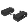
KST5088MTF
onsemi
TRANS NPN 30V 0.05A SOT23-3
R5000615XXWA
Powerex Inc.
DIODE GEN PURP 600V 150A DO205AA
AS1217MY
onsemi
INTEGRATED CIRCUIT
BCM5482SHEA2KFBG
Broadcom Limited
DUAL PORT 10/100/1000BASE-T PH S
FJB3307DTM
onsemi
TRANS NPN 400V 8A D2PAK
MAX1617MEE
Analog Devices Inc./Maxim Integrated
SENSOR DIGITAL -55C-125C 16QSOP
UHE1H182MHD
Nichicon
CAP ALUM 1800UF 20% 50V RADIAL
VI-J1L-IX
Vicor Corporation
DC DC CONVERTER 28V 75W
TS334IYDT
STMicroelectronics
IC COMPARATOR 4 GEN PUR 14SO
FCD5N60-F085
onsemi
FCD5N60_F085 - N-CHANNEL SUPERFE
TPS389001DSER
Texas Instruments
IC SUPERVISOR 1 CHANNEL 6WSON -
BZX84C30S-7-F
Diodes Incorporated
DIODE ZENER ARRAY 30V SOT363
DMN2015UFDE-7
Diodes Incorporated
MOSFET N-CH 20V 10.5A 6UDFN
C2139NLT
Pulse Electronics
XFRMR BALUN FOR WIDEBAND RF APP
SI8231BB-D-ISR
Skyworks Solutions Inc.
DGTL ISO 2.5KV GATE DRVR 16SOIC
AD9058AJD
Analog Devices Inc.
IC ADC 8BIT FLASH 48CDIP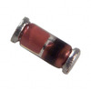
TZM5244B-GS08
Vishay General Semiconductor - Diodes Division
DIODE ZENER 14V 500MW SOD80
MAX4377HAUA
Analog Devices Inc./Maxim Integrated
IC CURRENT SENSE 2 CIRCUIT 8UMAX
C3216X7R2E683K160AA
TDK Corporation
CAP CER 0.068UF 250V X7R 1206
EL8403IUZ
Renesas Electronics America Inc
IC OPAMP GP 4 CIRCUIT 16QSOP
LM193AH
Texas Instruments
IC COMPARATOR 2 GEN PUR TO99-8
7440520018
Würth Elektronik
FIXED IND 1.8UH 2.6A 35 MOHM SMD
1808CC102KAT9A
KYOCERA AVX
CAP CER 1000PF 630V X7R 1808
LP3936SLX
Texas Instruments
IC LED DRV RGLTR PWM 32TLGA
KA1H0165RTU
onsemi
IC OFFLINE SW MULT TOP TO220F
74F14PC
Fairchild Semiconductor
IC INVERT SCHMITT 6CH 1-IN 14DIP
FQP32N20C
onsemi
MOSFET N-CH 200V 28A TO220-3
STM1811LWX7F
STMicroelectronics
IC SUPERVISOR 1 CHANNEL SOT23-3
TSM900N06CH
Taiwan Semiconductor Corporation
60V, 11A, SINGLE N-CHANNEL POWER -

JANTX1N825-1
Microchip Technology
DIODE ZENER 5.9V 500MW DO35
MAX17113ETL+
Analog Devices Inc./Maxim Integrated
IC PWR SUPPLY FOR LCD TV 40TQFN
08055C473KAT2P
KYOCERA AVX
CAP CER 0.047UF 50V X7R 0805
B5819W
HY Electronic (Cayman) Limited
DIODE SCHOTTKY 40V 1A SOD123
SE15PDHM3/84A
Vishay General Semiconductor - Diodes Division
DIODE GEN PURP 200V 1.5A DO220AA
LM3671MF-1.2
Texas Instruments
IC REG BUCK 1.2V 600MA SOT23-5
CD74HC238E
Texas Instruments
IC DECODER/DEMUX 1X3:8 16DIP
IXTY02N120P-TRL
IXYS
MOSFET N-CH 1200V 200MA TO252
FAR-G5KK-911M50-D4KE-Z
Taiyo Yuden
FILTER SAW 911.5MHZ 10SMD
VE-BAMD-EL
Vicor Corporation
HB VE-BAMD-EL ROHS
IR2085STR
Infineon Technologies
IC GATE DRVR HALF-BRIDGE 8SOIC
74F11PC
Fairchild Semiconductor
IC GATE AND 3CH 3-INP 14DIP
CIGT252010EH1R0MNE
Samsung Electro-Mechanics
FIXED IND 1UH 4.1A 30 MOHM SMD
BZX84C24-7-F
Diodes Incorporated
DIODE ZENER 24V 300MW SOT23-3
MT25QL256ABA1EW9-0SIT
Micron Technology Inc.
IC FLASH 256MBIT SPI 8WPDFN
TC1017-2.9VCTTR
Microchip Technology
IC REG LINEAR 2.9V 150MA SOT23-5
PIC16C74B-20I/PT
Microchip Technology
IC MCU 8BIT 7KB OTP 44TQFP
MX25L8006EM1J-12G
Macronix
IC FLASH 8MBIT SPI 86MHZ 8SOP