Understanding the IR2104 Half-Bridge Driver and Its Applications
The IR2104 is a high-speed driver IC that helps control high-power transistors like MOSFETs and IGBTs. This article explores its features, technical details, pin configuration, and common uses, along with instructions for operation. Whether you're looking to drive motors, build power supplies, or manage inverters, the IR2104 offers a simple and efficient solution.Catalog

Introduction to IR2104 Half-Bridge Driver
The IR2104 IC is designed to efficiently convert low-power signals into strong, high-current drives. It works as a high-speed half-bridge driver, commonly used to control high-power transistors like MOSFETs. This makes it a reliable choice for circuits requiring precise control over power delivery.
One of its notable features is its compatibility with standard CMOS and LSTTL logic levels. This means it can operate smoothly with signals as low as 3.3V, making it suitable for a wide range of devices and applications. Its typical output currents, with a source current of 0.21A and a sink current of 0.36A, further enhance its performance in high-power applications.
The IR2104’s design allows it to reference the output channels to both high and low sides, ensuring stable operation. Additionally, its compatibility with various logic levels, including those commonly used in modern circuits, enhances its usability. This capability, paired with its resistance to common issues like latch-ups, makes it a dependable choice for both professional and hobbyist projects.
With its monolithic construction and thoughtful design, the IR2104 provides a balanced combination of performance, reliability, and ease of use. Whether you're working on industrial systems or smaller electronic projects, this IC delivers consistent results while keeping the design process straightforward.
Key Features and Technical Specifications of IR2104
Features of IR2104
• Single PWM Input
The IR2104 operates with a single PWM input, simplifying signal control. This makes it straightforward to integrate into systems where precise pulse-width modulation is required for efficient performance.
• Shutdown Input Feature
A dedicated shutdown input allows you to disable both channels of the IC when needed. This feature is helpful for adding an extra layer of control and safety, especially in critical situations or when the circuit is idle.
• Screw Terminals for Load Supply and Load
The inclusion of screw terminals ensures secure connections for the load supply and load. These terminals make wiring convenient and reliable, reducing the chances of loose connections.
• Input and Logic Supply Head Connector
The input and logic supply are connected via a dedicated connector, which helps maintain an organized setup. This feature simplifies integration into various designs by reducing wiring complexity.
• Logic for Preventing Cross-Conduction
Built-in logic prevents the high-side and low-side switches from turning on simultaneously. This minimizes the risk of short circuits and increases the overall safety of the circuit.
• Floating Channel for Bootstrap Operation
The floating channel is optimized for bootstrap operation, enabling efficient driving of the high-side MOSFET. This is particularly beneficial in circuits where the high-side operates at elevated voltages.
• Tolerance to Negative Transient Voltage
The IR2104 is designed to tolerate negative transient voltages, ensuring stable operation even in electrically noisy environments. This makes the IC more reliable in various applications.
• Immunity to dV/dt
With immunity to rapid changes in voltage (dV/dt), the IR2104 maintains consistent performance in fast-switching conditions. This reduces the risk of erratic behavior in high-speed circuits.
• Undervoltage Lockout
This feature ensures the IC doesn’t operate when the supply voltage is too low. By doing so, it protects the IC and the circuit from potential damage caused by unstable power levels.
• Internally Set Deadtime
The IC includes an internally configured deadtime, which introduces a delay between switching the high-side and low-side transistors. This prevents simultaneous conduction and enhances reliability.
• High-Side Output in Phase with the Input
The high-side output aligns with the input signal’s phase, simplifying control and ensuring predictable circuit behavior, especially in synchronized operations.
• Shutdown Input Turns Off Both Channels
When activated, the shutdown input turns off both high-side and low-side channels. This makes it easy to disable the driver completely when needed for safety or maintenance.
• Matched Propagation Delay for Both Channels
The propagation delay for both channels is matched to maintain timing accuracy. This feature is particularly useful in applications where precise timing is necessary for reliable operation.
• Lead-Free Option Available
For environmentally friendly designs, the IR2104 offers a lead-free version. This makes it a safer and more sustainable choice for various electronic projects.
Characteristics of IR2104
| Type | Parameter |
| Average load current | 10amps |
| Peak current | 20amps |
| VCC voltage range | 12V ~ 36V DC |
| Logic gate voltage supply | 12-15V DC |
| Content of compatible input signals | 3.3V-15V |
| Fully operational | 600V |
| Gate drive supply range | from 10 to 20V |
| Operating Temperature | -40°C~150°C TJ |
| Pinout | SMD-based design |
| Package | 8-DIP |
IR2104 Pin Details and Configuration
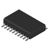
The IR2104 is designed with eight pins that are easy to mount and arranged in a standard through-hole layout. These pins are part of its compact 8-DIP package, which makes it simple to use in a variety of circuit designs. The IC is built with CMOS technology and includes two internal drivers. These drivers are specifically used to control an N-channel MOSFET and IGBT in a half-bridge gate setup.

Pin Configuration of IR2104
| Pin No. | Pin Name | Description |
| 1 | VCC | |
| 2 | IN | Input Pin |
| 3 | SD | Shutdown Pin (Active Low) |
| 4 | COM | Chip power and signal ground |
| 5 | LO | Low side gate driver output |
| 6 | VS | High side floating supply return |
| 7 | HO | High side gate driver output |
| 8 | VB | High side gate driver floating supply |
IR2104 Standard Schematic Diagram

Functional Block Diagram of IR2104

Equivalents for IR2104
• DGD2104
• IR2103
• IRS2104
• IR2153
• IR2110
Instructions for Using IR2104
The IR2104 half-bridge gate driver is designed to work seamlessly with controllers like the Arduino Uno, making it versatile for various applications. To operate it, you need to send PWM signals from the controller to the IC. When you connect the PWM signal from Arduino's pin D9 to the IR2104, it drives both the high-side and low-side MOSFETs efficiently.
For additional functionality, you can use the shutdown control feature. By connecting Arduino's pin D8 to the shutdown pin (pin three of the IR2104), you can enable or disable the driver as needed. This feature provides an extra layer of control, especially in scenarios where quick shutdown is necessary.
To ensure proper operation, the PWM signal must eventually reach its maximum duty cycle. This is required for the charge pump in the IR2104 to function as intended, maintaining stable operation of the circuit. By following these steps, you can make the most of the IR2104 in your projects.

Maximum Electrical Ratings of IR2104
| Symbol | Definition | Min | Max | Units |
| VS | High side floating absolute voltage | -0.3 | 625 | V |
| VB | High side floating supply offset voltage | VB - 25 | VB + 0.3 | V |
| VHO | High side floating output voltage | VS - 0.3 | VB + 0.3 | V |
| VCC | Low side and logic fixed supply voltage | -0.3 | 25 | V |
| VLO | Low side output voltage | -0.3 | VCC + 0.3 | V |
| VIN | Logic input voltage (IN & SD) | -0.3 | VCC + 0.3 | V |
| dVs/dt | Allowable offset supply voltage transient | 50 | V/ns | |
| PD | 1 | W | ||
| (8 lead SOIC) |
0.625 | W | ||
| RthJA | 125 | °C/W | ||
| (8 lead SOIC) | 200 | °C/W | ||
| TJ | Junction temperature | -55 | 150 | °C |
| TS | Storage temperature | -55 | 150 | °C |
| TL | 300 | °C |
Recommended Working Conditions for IR2104
Ambient Temperature
You need to ensure the ambient temperature (TA) remains within the range of -40°C to 125°C. This allows the IR2104 to operate safely and without overheating or malfunctioning in various environmental conditions.
Supply Voltage for Low Side and Logic
The supply voltage (VS) for the low side and logic must stay between 10V and 20V. Keeping the voltage within this range ensures proper functionality and avoids damage to the driver IC.
Absolute Voltage for High Side
The absolute voltage for the high side (VB) should be maintained between VS + 10V and VS + 20V. This range supports the high-side driver operations effectively without exceeding the limits of the device.
Floating Output Voltage for High Side
The floating output voltage for the high side should remain between VS and VB. This voltage range ensures the IR2104 can effectively drive the high-side MOSFET without issues.
Floating Offset Voltage for High Side
The floating offset voltage for the high side should range from Note 1 to 600V. This helps in handling varying load conditions and maintaining the stability of the driver IC.
Logic Input Voltage Range
The input voltage for the logic should be within 0V to VCC. This ensures compatibility with your controller’s signal levels, such as from a microcontroller or other input source.
Output Voltage for the Low Side
The output voltage for the low side should stay within 0V to VCC. This range allows the driver to control the low-side MOSFET gate effectively without causing stress or errors in operation.
Common Applications of IR2104
The IR2104 is a versatile IC that can be used in a wide range of applications. Here are its common uses, explained in a way to help you understand how it fits into different scenarios:
DC-DC Power Supplies
The IR2104 plays a key role in DC-DC power supplies by efficiently driving the high-power transistors required for voltage conversion. This makes it suitable for use in systems where stable and efficient voltage regulation is necessary.
Motor Drive Boards
This IC is often used in motor drive boards to control the high and low sides of MOSFETs or IGBTs, ensuring smooth and precise motor operation. It’s ideal for applications requiring consistent speed and torque management.
Driving High-Power Switching Devices
The IR2104 is designed to handle high-power switching devices like MOSFETs and IGBTs. It ensures reliable operation by providing the necessary drive signals to control these components efficiently.
Power Supplies
In power supply circuits, the IR2104 helps manage the switching elements, ensuring stable power delivery. Its ability to handle high-speed switching makes it a reliable choice for both industrial and commercial power systems.
Inverters
The IR2104 is commonly used in inverter circuits to drive the transistors that convert DC power to AC. Its precise control capabilities make it a dependable component for applications like renewable energy systems and industrial inverters.
Physical Package of IR2104

Comparison Between IR2104 and IR2101
| IR2104 | IR2101 | |
| Package | SOIC-8 | DIP-8 |
| Driver | 600V 2-OUT | High and Low Side |
| Logic input compatible | Standard CMOS or LSTTL | N/A |
Conclusion
The IR2104 is a reliable and versatile driver IC that helps manage high-power transistors with ease. Its features and simple design make it a great choice for various applications, such as motor drives, power supplies, and inverters. Whether you're working on a project or upgrading a system, the IR2104 offers performance you can depend on.
About us
ALLELCO LIMITED
Read more
Quick inquiry
Please send an inquiry, we will respond immediately.
Frequently Asked Questions [FAQ]
1. What is the IR2104 used for?
The IR2104 is used to drive high-power switching devices like MOSFETs and IGBTs. It can control both the high-side and low-side MOSFETs, making it suitable for various applications, including motor drives and power supplies.
2. What is a half-bridge gate driver?
A half-bridge gate driver is a type of circuit designed to control N-channel MOSFETs and IGBTs. It drives both high-side and low-side transistors, enabling efficient operation in circuits requiring high-speed switching and voltage control.
3. How is the IRS2104 different from the IR2104?
The IRS2104 has faster rise and fall times compared to the IR2104. This means it switches signals more quickly, which can improve performance in high-frequency applications.
4. Why is the IR2104 MOSFET driver not working?
If the IR2104 is not functioning, the SD pin may not be activated properly. To enable the IC, you need to keep the SD pin high. Additionally, a base resistor must be included; without it, the IN input cannot exceed approximately 0.7 volts, which prevents the IC from activating.
5. What is the difference between a full-bridge and a half-bridge gate driver?
A half-bridge driver includes one low-side and one high-side driver, allowing it to control two transistors (Q1 and Q2 or Q3 and Q4) at the same time. In contrast, a full-bridge driver has two low-side and two high-side drivers, enabling it to control four transistors simultaneously for more complex applications.

Comprehensive Guide to 74HC27/74LS27: Triple 3-Input NOR Gates
on December 2th

Differences Between LM358 and LM393 Explained
on December 2th
Popular Posts
-

Understanding Power Supply Voltages in Electronics VCC, VDD, VEE, VSS, and GND
on June 13th 24175
-

USB-C Pinout and Features
on June 13th 21286
-

The Ultimate Guide to Wire Color Codes in Modern Electrical Systems
on January 1th 17465
-

TL494 Current-Mode PWM Controller IC
on January 1th 14733
-

Current Divider Circuits and Effective Use of the Divider Formula
on January 1th 13630
-

FET (Field Effect Transistor) Circuit Symbols
Field-Effect Transistors (FETs) are widely used in modern electronics and are found in everything from simple devices to complex digital systems. To work with these transistors effectively, it's helpful to understand the symbols that represent different types of FETs. These symbols do more than just show what the transistors look like—they also provide information about how each transistor works ...on January 1th 13440
-

Quality (Q) Factor: Equations and Applications
The quality factor, or 'Q', is important when checking how well inductors and resonators work in electronic systems that use radio frequencies (RF). 'Q' measures how well a circuit minimizes energy loss and impacts the range of frequencies the system can handle around its main frequency. In systems with inductors, capacitors, and tuned circuits, a higher 'Q' means the circuit focuses more on a spe...on January 1th 13393
-

Understanding and Building Op-Amp Based Peak Detectors
In the world of electronic circuit design, peak detectors are key tools for accurately analyzing and processing signal strengths. These circuits are designed to find and keep the highest signal amplitude, making sure the peak value is precisely captured and held as needed. Peak detectors are important in many fields, from improving audio quality in communication systems to aiding medical diagnoses...on June 13th 12497
-

LM741 Op-Amp: Features, Specifications, and Applications
The LM741 op-amp is a popular and flexible electronic component. This article goes over the pin layout, functions, specs, and different ways the LM741 can be used, while also comparing it to similar models like the LM358.Catalog1. What Is the LM741 Op-Amp?2. The LM741 Pin Configuration3. The LM741 Pin Functions4. Specifications of the LM7415. Features of LM7416. LM741 Circuit Applications7. LM741 ...on June 13th 12034
-

ST-LINK/V2: Pinout, Specifications, and Datasheet
This article takes you through the ST-LINK/V2, a well-regarded tool that amplifies connectivity and functionality. Key topics will cover its pinout configuration, delve into its 3D model, and spotlight specifications. Such understanding expands the horizons of STM microcontrollers in diverse applications. By grasping these interfaces and tools, you can transform embedded systems, opening doors to ...on January 1th 11579


