
TVS Diodes Explained: Working, Types, Specifications, and Applications
In this article, you’ll learn what TVS (Transient Voltage Suppression) diodes are and how they protect circuits from sudden voltage spikes caused by ESD, lightning, or switching. You’ll see how they work under normal conditions, during surges, and how they reset automatically. You’ll explore different types, key specifications, and where each one fits best. You’ll also discover their common uses in data lines, automotive, and IoT systems, along with practical installation tips and package options.Catalog

Figure 1. Transient Voltage Suppression Diodes
What are TVS Diodes?
TVS (Transient Voltage Suppression) diodes are protective semiconductor devices designed to shield electronic circuits from sudden voltage spikes. These spikes often come from electrostatic discharge, lightning, or inductive switching. Under normal conditions, a TVS diode allows only minimal leakage current and remains non-conductive. When the voltage exceeds its breakdown point, it instantly conducts, clamping the excess voltage and channeling the surge to ground. After the transient passes, it automatically returns to its non-conductive state, ready to protect again.
How TVS Diodes Work?

Figure 2. Typical TVS Diode Surge Clamping Circuit
The figure above shows a typical protection circuit where a TVS diode is connected between the signal line and ground, right next to the protected load. The input line may experience a sudden surge, represented by the sharp “Transient Voltage” spike. When this happens, the TVS diode reacts instantly, clamping the excess voltage and diverting the surge current to ground. As a result, the load sees only a controlled “Clamped Transient” rather than the full spike.
Normal Operation
Under normal voltage conditions, the TVS diode behaves like an open circuit. Only a very small leakage current flows through it, so it doesn’t interfere with the protected circuit. The entire line voltage is delivered to the load without any significant drop.
During a Transient Surge
When a surge pushes the line voltage above the diode’s breakdown level, the diode rapidly enters avalanche mode. It creates a low-impedance path to ground, forcing the excess surge current away from the load. In this brief moment (within picoseconds to nanoseconds) the voltage across the load is held close to the diode’s clamping voltage, as shown in the “Clamped Transient” section of the waveform in the figure.
Returning to Normal
Once the surge ends and the line voltage falls back below the breakdown threshold, the diode automatically stops conducting and returns to its high-impedance state. There’s no need for any reset, allowing the diode to stand by for the next event. This quick transition makes TVS diodes ideal for continuous, maintenance-free circuit protection.
Types of TVS Diodes

Figure 3. Unidirectional vs Bidirectional TVS Diode Characteristics
The figure above compares how unidirectional and bidirectional TVS diodes behave under normal signals and during surge or ESD events.
Unidirectional TVS Diodes
Unidirectional TVS diodes are used mainly in DC circuits or signal lines that operate in a single polarity. In normal operation, when the voltage stays within the reverse standoff range, the diode remains off, allowing the signal to pass without interference (shown in the central non-conducting region of the left graph). When a surge pushes the voltage above the breakdown level, the diode conducts in reverse, clamping the line near its clamping voltage VC. For a positive surge, it acts like a standard rectifier and clamps near the forward voltage VF. This type is placed across power supply rails and unidirectional signal lines to absorb reverse transients effectively.
Bidirectional TVS Diodes
Bidirectional TVS diodes are used for AC signals or lines that swing in both positive and negative directions. As shown on the right side of the figure, they remain non-conductive during normal bidirectional signal swings, providing no interference to the line. When a surge exceeds either the positive or negative breakdown voltage, the diode conducts symmetrically in both directions, clamping the voltage to a safe level on either side. This makes them ideal for protecting audio lines, communication ports, and high-speed differential interfaces where polarity changes continuously. Their balanced conduction ensures consistent protection regardless of surge direction.
Specifications of TVS Diodes
|
Parameter |
Specification |
|
Reverse
Standoff Voltage (VRWM) |
5.0
V |
|
Breakdown
Voltage (VBR) @ IT=1 mA |
6.4
V – 7.0 V (at 25 °C) |
|
Clamping
Voltage (VC) |
9.2
V at IPP=65.2 A (10/1000 µs) |
|
Peak
Pulse Current (IPP) |
65.2
A (10/1000 µs) |
|
Peak
Pulse Power (PPP) |
600
W (10/1000 µs standard surge waveform) |
|
Reverse
Leakage Current (IR) |
≤
800 µA @ VRWM, 25 °C |
|
Junction
Capacitance (Cj) |
≈
700 pF typ. (0 V, 1 MHz) |
|
Forward
Voltage (VF) |
3.5
V typ. @ IF=50 A |
|
Dynamic
Resistance (RDYN) |
≈
0.04 Ω typ. (calculated from VC) |
|
Thermal
Resistance (θJA) |
≈
75 °C/W (on standard JEDEC FR-4 PCB) |
|
Operating
Junction Temperature |
−55
°C to +150 °C |
|
Storage
Temperature |
−55
°C to +150 °C |
|
Polarity |
Unidirectional |
|
Surge
Waveform (IEC 61000-4-5) |
8/20
µs (for surge current testing) |
|
Industry
Power Rating Waveform |
10/1000
µs (per JEDEC standard) |
Advantages of TVS Diodes
• Reacts in picoseconds to clamp dangerous voltages
• Holds the voltage tightly near the breakdown point, better than MOVs or GDTs
• Can manage high peak currents and power for short durations
• Returns to its non-conductive state immediately after the surge
• Maintains performance with little aging or drift
• Avoids interference with normal operation
• Offered in small SMD and multi-channel array packages
• Effective against ESD, EFT, lightning, and inductive spikes
• Reduces failures and prevents overvoltage damage
• Lowers downtime and replacement costs
Applications of TVS Diodes
TVS diodes are widely used wherever sensitive electronic circuits are exposed to sudden voltage spikes or electrostatic discharge.
USB and Communication Lines
TVS diodes protect data lines such as USB, HDMI, and Ethernet from ESD and surge events. They are placed close to connectors to absorb fast voltage spikes before they can reach delicate transceivers. This ensures stable data transmission and prevents damage to communication ICs.
Automotive Systems
In vehicles, TVS diodes guard ECUs, sensors, communication buses (like CAN and LIN), and infotainment units from load dumps and inductive switching noise. They are designed to withstand harsh electrical environments and large transient energy levels. Their use improves system reliability and extends the lifespan of automotive electronics.
Industrial Control
Industrial control systems operate in noisy electromagnetic environments where switching machinery generates frequent surges. TVS diodes protect PLC inputs, control panels, and motor drives by clamping these transients before they disrupt signals. This helps maintain stable operation and prevents costly downtime.
Power Supplies
Power lines can carry dangerous spikes from switching or lightning events. TVS diodes placed across DC rails act as surge barriers, instantly clamping overvoltages. This protects downstream circuits and helps maintain stable supply voltage for sensitive components.
Telecommunication Equipment
Communication systems, including Ethernet switches, DSL lines, and RF modules, are prone to surge damage from lightning and cable discharges. TVS diodes protect these interfaces by clamping voltages to safe levels without interfering with high-speed signals. Their use improves network reliability and reduces equipment failures.
Renewable Energy Systems
Solar panels, inverters, and battery management systems are often exposed to surges from switching and lightning. TVS diodes placed at input and communication interfaces prevent these surges from damaging sensitive electronics. They help maintain stable power conversion and extend equipment life.
IoT and Embedded Systems
TVS diodes are used in IoT devices to protect GPIO pins, serial interfaces, and wireless modules from external ESD events. Compact SMD packages make them ideal for space-limited circuit boards. This protection ensures device stability in outdoor and consumer environments.
How to Install TVS Diodes?
Step 1: Choose the correct diode
Match the reverse standoff voltage (VRWM) to the line’s maximum operating voltage with a small safety margin. Decide on unidirectional for DC rails or bidirectional for AC/differential signals, and check that the clamping voltage (VC) stays below the protected IC’s absolute maximum. For high-speed lines, confirm the diode’s capacitance and dynamic resistance are low enough to preserve signal integrity.
Step 2: Place it at the entry point
Position the TVS as the first component behind the connector, I/O pin, or power jack so the surge meets the diode before any trace reaches your IC. Avoid long detours or stubs between the connector and the diode. Short distance means less inductance and faster, tighter clamping.
Step 3: Keep traces short and wide
Route from the line to the TVS with a short, wide trace to reduce series inductance. Minimize loop area between the line, the TVS, and ground to prevent voltage overshoot during fast edges. If possible, place the line pad and the TVS pad on the same layer to avoid via inductance.
Step 4: Provide a low-impedance ground path
Tie the TVS ground pad directly to a solid ground plane using multiple vias placed right at the pad. Do not share long return paths with sensitive signals. A stout ground return lets the surge current bypass your load instead of lifting the local ground.
Step 5: Check orientation
For unidirectional devices, connect the cathode (banded end) to the protected line and the anode to ground; reverse connection will leave the rail unprotected. Bidirectional devices are symmetrical, so orientation is not needed. Verify markings against the datasheet before soldering.
Step 6: Solder with care
Follow the recommended reflow or hand-soldering profile to avoid overheating the package. Clean flux residues if required and inspect for bridges or cold joints. Handle the board with ESD-safe practices so you don’t stress the very parts you’re installing.
Step 7: Verify after assembly
Do a quick continuity and polarity check with a multimeter; confirm no shorts line-to-ground and that the diode’s forward drop looks reasonable (for unidirectional parts). Power the circuit and confirm the protected rail operates normally with minimal leakage. If available, monitor the line on an oscilloscope to ensure noise performance is unchanged.
Step 8: Validate with controlled surges
Use an ESD gun or surge generator, if accessible, to apply standard test pulses (e.g., IEC 61000-4-2) at the connector. Watch the rail with a scope to confirm the voltage clamps near VC and the load remains unharmed. Record pass/fail levels to finalize your protection design.
TVS Diodes vs Other Protection Devices
TVS diodes are not the only option for protecting circuits from voltage surges. The table below compares their key characteristics with other common protection devices like MOVs, Zener diodes, and GDTs to highlight their strengths and ideal use cases.
|
Feature |
TVS
Diodes |
MOVs |
Zener
Diodes |
GDTs |
|
Response
Time |
Very
fast (under 1 ns) |
Fast
(1–100 ns) |
Moderate
(100 ns–1 µs) |
Slow
(0.1–10 µs) |
|
Clamping
Voltage |
Tight
control (≈5–600 V depending on type) |
Higher,
loose (≈130–1000 V) |
Set
by breakdown (≈2.4–200 V) |
After
firing, very low (≈20–50 V), but high before trigger |
|
Breakdown
/ Trigger Voltage |
Sharp,
defined (a few volts above normal) |
Around
rated varistor voltage (e.g., 230 V RMS - 360 V DC clamp) |
Fixed
Zener voltage (e.g., 5.1 V, 12 V, etc.) |
High
trigger (≈75–1000 V depending on type) |
|
Energy
Handling |
Medium
(tens to hundreds of joules) |
High
(hundreds to thousands of joules) |
Low
(below 5 W usually) |
Very
high (thousands of joules) |
|
Repetition
Capability |
Handles
many hits well |
Degrades
with repeated surges |
Not
for big surges |
Can
handle many hits if surge within limit |
|
Leakage
Current |
Very
low (nA to µA) |
Low
to moderate (µA) |
Low
(µA) |
Almost
zero |
|
Capacitance |
Low
(as low as 1 pF for signal lines) |
Higher
(hundreds to thousands pF) |
Moderate
(tens to hundreds pF) |
Very
low (below 1 pF) |
|
Size
/ Mounting |
Small,
SMD or leaded |
Bigger,
disk or block type |
Very
small, like regular diodes |
Bulky,
cylindrical |
|
Typical
Use |
Data
lines, power rails, ESD |
Power
mains, surge protectors |
Voltage
regulation, light protection |
Telecom
lines, lightning protection |
|
Failure
Mode |
Usually
shorts or opens |
Gradual
degradation, may short |
Overheat
or short if overstressed |
May
stay on or not trigger if damaged |
TVS Diode Package Options
TVS diodes are available in different package types to fit various circuit layouts and applications. The sections below highlight the most common options and their typical uses.
Surface-Mount Packages

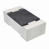
Figure 4. Surface-Mount Packages
Surface-mount TVS diodes are compact SMD types designed for automated PCB assembly. They are widely used in consumer electronics, computers, and communication devices where space is limited and high production efficiency is required. These packages offer excellent electrical performance with low parasitics, making them ideal for protecting data lines and power rails. Common SMD outlines include SOD, SMB, and SMC packages.
High-Power Packages

Figure 5. High-Power Packages
High-power TVS packages are built to handle larger surge currents and energy levels. They often use stud-mount or large SMC formats to provide strong thermal dissipation and mechanical strength. These packages are found in automotive electronics, industrial power systems, and outdoor equipment exposed to severe surges. Their robust construction ensures reliable protection in high-stress environments.
Low-Profile SMD Packages

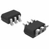
Figure 6. Low-Profile SMD Packages
Low-profile SMD TVS diodes are designed for ultra-thin devices where board height is restricted. They retain the surface-mount advantages while minimizing vertical space, making them suitable for smartphones, tablets, and wearable electronics. Despite their slim form, they provide effective transient suppression for both power and signal lines. These packages are ideal for modern compact designs that demand both protection and space efficiency.
Axial Leaded Packages

Figure 7. Axial Leaded Packages
Axial leaded TVS diodes are traditional through-hole types used in power supplies and legacy equipment. They feature leads extending from both ends, allowing easy insertion through PCB holes or inline wiring. These packages offer strong mechanical stability and are suitable for higher power applications where automated SMD assembly is not required. Typical styles include DO-15, DO-41, and similar cylindrical packages.
Conclusion
TVS diodes offer rapid clamping, stable performance, and automatic recovery after a surge. Choosing the right type involves matching voltage ratings, clamping levels, current capacity, and capacitance to the application. Proper placement, grounding, orientation, and testing ensure maximum protection. They enhance reliability across various systems and outperform many alternatives in speed and precision. Multiple package styles make them suitable for both compact electronics and high-power environments.
About us
ALLELCO LIMITED
Read more
Quick inquiry
Please send an inquiry, we will respond immediately.
Frequently Asked Questions [FAQ]
1. Can one TVS diode protect multiple signal lines?
Typically, a single TVS diode protects one line, but multi-channel TVS arrays are available to protect multiple data lines in compact spaces. These are common in USB, HDMI, and Ethernet applications, offering multiple protection channels in one SMD package.
2. Are TVS diodes reusable after a surge event?
Yes, TVS diodes are designed to recover automatically after a transient. As long as the surge is within their rated limits, they return to their non-conductive state and continue to provide protection without manual resetting or replacement.
3. What’s the difference between using a TVS diode and a fuse?
A fuse cuts off current after an overload and must be replaced or reset, while a TVS diode clamps voltage spikes instantly and remains in the circuit. TVS diodes protect against short, high-energy transients, whereas fuses handle sustained overcurrent situations.
4. Do TVS diodes affect signal quality on high-speed data lines?
They can if the capacitance is too high. For USB, HDMI, or differential pairs, select low-capacitance TVS diodes (as low as 1 pF) to maintain signal integrity while still providing ESD and surge protection.
5. Can TVS diodes protect against lightning strikes?
Yes, but only within their rated surge handling capacity. For direct or large indirect lightning surges, TVS diodes are typically used alongside other protection devices like GDTs or MOVs for layered protection in telecom and outdoor power systems.

A Detailed Guide to CR2016, BR2016, LiR2016, and Their Battery Equivalents
on July 24th

A-Size Battery: Dimensions, Specifications, Equivalents and Applications
on October 14th
Popular Posts
-

Complex Instruction Set Computers: How They Changed Computing?
on June 4th 148298
-

USB-C Pinout and Features
on June 4th 129904
-

Using Xilinx Unified Simulation Primitives: A Comprehensive Guide to FPGA Design and Simulation
on June 4th 111778
-

Power Supply Voltages in Electronics: Meaning of VCC, VDD, VEE, VSS, and GND
on June 4th 93324
-

RJ45 Connector Guide: Pinout, Wiring, Cable Types, and Uses
on January 1th 92002
-

The Ultimate Guide to Wire Color Codes in Modern Electrical Systems
The way our electrical systems use colors isn’t just for looks. Each wire color now indicates a specific function, making it easier to identify and handle electrical components correctly during ins...on January 1th 76116
-

Quality (Q) Factor: Equations and Applications
The quality factor, or 'Q', is important when checking how well inductors and resonators work in electronic systems that use radio frequencies (RF). 'Q' measures how well a circuit minimizes energy...on January 1th 74018
-

Purge Valve Guide: Function, Symptoms, Testing, and Replacement for Optimal Engine Performance
The purge valve is a key part of a car’s system that helps keep the air clean by managing fuel vapors before they can escape into the atmosphere. This not only helps the environment by reducing pol...on January 1th 68021
-
Understanding Capacitors and Their Symbols in Circuit Diagrams
Capacitors are small parts used in almost all electronic devices. They store and release electrical energy and are found in things like power supplies, radios, and circuits that help reduce noise. ...on June 4th 57890
-

A23 Battery Specifications and Compatibility
The A23 battery is a small, cylinder-shaped battery with high voltage. Also called 23A, 23AE, or MN21, it runs at 12 volts and much higher than AA or AAA batteries. Its special design make...on January 1th 57471
HOT Part Number
-
RC0402JR-072K7L
Yageo
RES SMD 2.7K OHM 5% 1/16W 0402
1N5335B
Microsemi Corporation
DIODE ZENER 3.9V 5W T18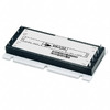
VI-263-IY
Vicor Corporation
DC DC CONVERTER 24V 50W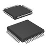
XRT75L00IV-F
MaxLinear, Inc.
IC TELECOM INTERFACE 52TQFP
TLV3502AQDCNRQ1
Texas Instruments
IC COMPARATOR 2 GEN PUR SOT23-8
MP2308GD-Z
Monolithic Power Systems Inc.
IC REG BUCK ADJ 4A 14FCQFN
TSV632IDT
STMicroelectronics
IC OPAMP GP 2 CIRCUIT 8SOIC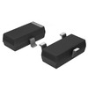
KST5088MTF
onsemi
TRANS NPN 30V 0.05A SOT23-3
R5000615XXWA
Powerex Inc.
DIODE GEN PURP 600V 150A DO205AA
AS1217MY
onsemi
INTEGRATED CIRCUIT
BCM5482SHEA2KFBG
Broadcom Limited
DUAL PORT 10/100/1000BASE-T PH S
FJB3307DTM
onsemi
TRANS NPN 400V 8A D2PAK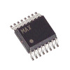
MAX1617MEE
Analog Devices Inc./Maxim Integrated
SENSOR DIGITAL -55C-125C 16QSOP
UHE1H182MHD
Nichicon
CAP ALUM 1800UF 20% 50V RADIAL
VI-J1L-IX
Vicor Corporation
DC DC CONVERTER 28V 75W
TS334IYDT
STMicroelectronics
IC COMPARATOR 4 GEN PUR 14SO
FCD5N60-F085
onsemi
FCD5N60_F085 - N-CHANNEL SUPERFE
TPS389001DSER
Texas Instruments
IC SUPERVISOR 1 CHANNEL 6WSON -
BZX84C30S-7-F
Diodes Incorporated
DIODE ZENER ARRAY 30V SOT363
DMN2015UFDE-7
Diodes Incorporated
MOSFET N-CH 20V 10.5A 6UDFN
C2139NLT
Pulse Electronics
XFRMR BALUN FOR WIDEBAND RF APP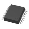
SI8231BB-D-ISR
Skyworks Solutions Inc.
DGTL ISO 2.5KV GATE DRVR 16SOIC
AD9058AJD
Analog Devices Inc.
IC ADC 8BIT FLASH 48CDIP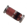
TZM5244B-GS08
Vishay General Semiconductor - Diodes Division
DIODE ZENER 14V 500MW SOD80
MAX4377HAUA
Analog Devices Inc./Maxim Integrated
IC CURRENT SENSE 2 CIRCUIT 8UMAX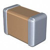
C3216X7R2E683K160AA
TDK Corporation
CAP CER 0.068UF 250V X7R 1206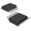
EL8403IUZ
Renesas Electronics America Inc
IC OPAMP GP 4 CIRCUIT 16QSOP
LM193AH
Texas Instruments
IC COMPARATOR 2 GEN PUR TO99-8
7440520018
Würth Elektronik
FIXED IND 1.8UH 2.6A 35 MOHM SMD
1808CC102KAT9A
KYOCERA AVX
CAP CER 1000PF 630V X7R 1808
LP3936SLX
Texas Instruments
IC LED DRV RGLTR PWM 32TLGA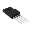
KA1H0165RTU
onsemi
IC OFFLINE SW MULT TOP TO220F
74F14PC
Fairchild Semiconductor
IC INVERT SCHMITT 6CH 1-IN 14DIP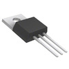
FQP32N20C
onsemi
MOSFET N-CH 200V 28A TO220-3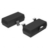
STM1811LWX7F
STMicroelectronics
IC SUPERVISOR 1 CHANNEL SOT23-3
TSM900N06CH
Taiwan Semiconductor Corporation
60V, 11A, SINGLE N-CHANNEL POWER -

JANTX1N825-1
Microchip Technology
DIODE ZENER 5.9V 500MW DO35
MAX17113ETL+
Analog Devices Inc./Maxim Integrated
IC PWR SUPPLY FOR LCD TV 40TQFN
08055C473KAT2P
KYOCERA AVX
CAP CER 0.047UF 50V X7R 0805
B5819W
HY Electronic (Cayman) Limited
DIODE SCHOTTKY 40V 1A SOD123
SE15PDHM3/84A
Vishay General Semiconductor - Diodes Division
DIODE GEN PURP 200V 1.5A DO220AA
LM3671MF-1.2
Texas Instruments
IC REG BUCK 1.2V 600MA SOT23-5
CD74HC238E
Texas Instruments
IC DECODER/DEMUX 1X3:8 16DIP
IXTY02N120P-TRL
IXYS
MOSFET N-CH 1200V 200MA TO252
FAR-G5KK-911M50-D4KE-Z
Taiyo Yuden
FILTER SAW 911.5MHZ 10SMD
VE-BAMD-EL
Vicor Corporation
HB VE-BAMD-EL ROHS
IR2085STR
Infineon Technologies
IC GATE DRVR HALF-BRIDGE 8SOIC
74F11PC
Fairchild Semiconductor
IC GATE AND 3CH 3-INP 14DIP
CIGT252010EH1R0MNE
Samsung Electro-Mechanics
FIXED IND 1UH 4.1A 30 MOHM SMD
BZX84C24-7-F
Diodes Incorporated
DIODE ZENER 24V 300MW SOT23-3
MT25QL256ABA1EW9-0SIT
Micron Technology Inc.
IC FLASH 256MBIT SPI 8WPDFN
TC1017-2.9VCTTR
Microchip Technology
IC REG LINEAR 2.9V 150MA SOT23-5
PIC16C74B-20I/PT
Microchip Technology
IC MCU 8BIT 7KB OTP 44TQFP
MX25L8006EM1J-12G
Macronix
IC FLASH 8MBIT SPI 86MHZ 8SOP