
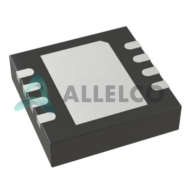
LTC2875IDD#TRPBF (1)
Manufacturer Part Number
LTC2875IDD#TRPBF
Manufacturer
Analog Devices
Introduction
The LTC2875 is a robust CANbus transceiver designed for high-speed automotive and industrial applications.
Product Features and Performance
High-Speed CAN Transceiver
Supports up to 4Mbps Data Rate
Fail-Safe Features against Bus Faults
Extended Common-Mode Range: -12V to 12V
Thermal Shutdown Protection
Power Up/Down Glitch-Free Operation
Low Current Shutdown Mode
HBM ESD Protection ±15kV on CAN Bus Pins
Product Advantages
High Noise Immunity
Thermal Protection Enhances Reliability
Wide Voltage Range to Accommodate Various Supply Levels
Suitable for 12V and 24V Systems
Key Technical Parameters
Protocol: CANbus
Number of Drivers/Receivers: 1/1
Voltage - Supply: 3V ~ 3.6V, 4.5V ~ 5.5V
Data Rate: up to 4Mbps
Operating Temperature Range: -40°C ~ 85°C
Quality and Safety Features
Protection Against -40V to 40V Overvoltage Faults
Short-Circuit and Overtemperature Protection
ISO 11898 Compliant
Compatibility
Pin Compatible with Standard CAN Transceivers
CAN 2.0 Part A and Part B Compatible
Application Areas
Automotive Networks
Industrial Automation Systems
Heavy Equipment
Networking and Data Communication
Product Lifecycle
Active Product Status
Not Nearing Discontinuation
Replacements or Upgrades Typically Not Required
Several Key Reasons to Choose This Product
Support for High-Speed Communication
Enhanced Safety with Built-in Protections
Reliable Performance in Extreme Conditions
Compatible Across a Broad Range of Applications
Low Power Shut Down Mode for Energy Savings
Designed for Rugged Environments with Wide Temperature Range and High Voltage Tolerance
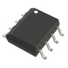
 LTC2875IS8#PBFAnalog Devices Inc.IC TRANSCEIVER 1/1 8SO
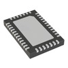 LTC2874IUHF#TRPBFAnalog Devices Inc.IC TRANSCEIVER HALF 4/4 38QFN
 LTC2875HS8#PBFAnalog Devices Inc.IC TRANSCEIVER 1/1 8SO
 LTC2875IDDLinear Technology / Analog Devices
 LTC2874IUHF#TRPBF


